Ijraset Journal For Research in Applied Science and Engineering Technology
- Home / Ijraset
- On This Page
- Abstract
- Introduction
- Conclusion
- References
- Copyright
A Brief Introduction to Fiber Optic Sensors and their Types with Applications
Authors: Muhammad Arif Bin Jalil
DOI Link: https://doi.org/10.22214/ijraset.2023.54823
Certificate: View Certificate
Abstract
Materials measurement and environmental assessment have traditionally employed optical measurement techniques like polarimetry, spectrometry, and interferometry. The application of these fundamental ideas is made even more flexible by the optical fibre. For more than 30 years, fiber-optic technology has achieved significant advances in measurement science.While by no means thorough, this study’s perspective on these contributions illustrates the significant conceptual advancements made in the early years of optical fibre technology and the range of applications that have arisen. Applying guided-wave optics to novel and difficult measurement requirements, such as microsystems characterization, cellular biology, and art restoration, presents clear prospects for further extensive study.
Introduction
I. INTRODUCTION
Without a doubt, Fibre optics has had a significant impact on the communications sector [1]. This can be linked to the key papers of Kao and Hockham, Simon and Spitz, and others [2, 3], who recognised in the early to mid-1960s that optical signals might be conveyed via glass or silica fibres with a loss that might be lower than that experienced in coaxial copper cables. Furthermore, the loss in optical fibres could be maintained for all possible modulation frequencies, unlike copper where it increases loss with baseband modulation frequency. A while later, Dyott [4] discovered that the silica transmission characteristic contained zones with negligible dispersion.
Fibre optics had already existed in 1965. Glass fibres had already been used in decorative lamps, and the fundamental concepts of the electrical waveguide were well known. It had already become commonplace to use optical fibres to direct light to and from a location where a measurement was to be performed.
The first fiber-optic sensing patents had been submitted and had appeared as a test product [5] mentioned in the literature.Eli Snitzer's ever-innovative mind proposed employing fibre optics to send phase-modulated signals around the same time [6], which served as the foundation for another significant class of fiber-optic sensors.As a result, this study will primarily focus on the historical history of research, development, and applications of fiber-optic sensor technology. The optical fibre sensor (OFS) community became influnced with communications enthusiasm over 35 years ago, and by the mid-1970s to the early 1980s, they believed that OFS technology was the answer to all of their problems. Though perhaps a little slowly, realism has percolated, and today we are aware of areas of genuine application, but there are still intriguing and important concerns that can excite the research community.
II. SENSING APPLICATIONS
Sensing and measurement require a high level of skill. Applications-specific sensor technologies are available. All sensors work in specialised industries. The sensing mechanisms are based on countless physical and chemical phenomena that are interfaced to electronic signal conditioning via countless more custom-designed protocols. Because of this, the market is very fragmented, which causes dissatisfaction and difficulty for those who work in it. Since fiber-optic communications uses a very large number of what are essentially the same system configurations and components, fiber-optic sensing is philosophically opposed to those technologies. The practise of communications industry spin-offs into sensor technology is quite rare. Another crucial generic aspect of sensing techniques.
The transduction process uses virtually all physical and chemical processes, all of which are temperature sensitive. Temperature is not a factor in the majority of measurements. Because of this, temperature changes must first be corrected for in most sensing and measurement systems. This is a persistent problem that has undoubtedly influenced fiber-optic sensor technology, leading to approaches and solutions with varied degrees of elegance and ingenuity.

Figure 1 and Figure 2 presents a diagrammatic illustration of the fibre sensor. Simple fundamental elements are used. Using an optical fibre, light is transported to a modulation region where it is modified by a physical, chemical, or biological phenomenon. The modulated light is then carried back to a receiver where it is detected and demodulated. Ideally, the demodulated signal and the phenomenon of interest have a one-to-one correspondence . The first step is to guarantee that the parameter to be measured and the demodulated signal have a one-to-one relationship; the second is to match the technology to the application in terms of both performance and cost. Although the impact of the fibres to and from the modulation region, variations in source and detector characteristics with temperature and time, and the impact of temperature on the modulation process are all significant, the first of important problems these is the simpler one. The second of these must acknowledge the existence of established methodologies and, in particular, must identify otherwise unsolvable issues that are crucial but have not been adequately addressed due to technical issues.
Intrinsic Type Fiber Optic Sensors, sensing takes place within the fiber itself. The ability of the sensors to translate an environmental action into a change of the light beam flowing through them depends on the characteristics of the optical fibre itself. In this case, the frequency, phase, polarisation, or intensity of the light signal might be considered one of its physical qualities. The intrinsic fibre optic sensor's ability to deliver distributed sensing across great distances is its most advantageous characteristics. In fibre optic sensors of the extrinsic type, the fibre may serve as a means of transporting information to a black box.
Depending on the information received at the receiver, it produces a light signal. Rotation, vibration velocity, displacement, twisting, torque, and acceleration are all measured with these sensors. The capacity of these sensors to access locations that would otherwise be inaccessible is their main advantage. [7]
IV. INTENSITY MODULATED SENSOR
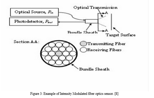
In particular, for the high numerical aperture fibres uniformly illuminated with light from an incandescent bulb for which the sensor was originally designed, the fraction of light transmitted between the receive elements in the bundle and the transmit elements in the bundles depends on the separation between the reflector and the bundle itself and is, to a first approximation, independent of small rotational angles of the target object. Of course, the transmission ratio will change if the target's reflectivity varies. However, the inventors had anticipated this possibility and created compensatory plans to solve the issue. These required the employment of two receiving bundles, each placed a certain distance apart. Therefore, the distance between the bundle's end and the target determines how much light is received in each of these receiving bundles. As a proximity measurement system, the Fotonic sensor has shown some limited success in real applications. It possessed micrometer-level resolution, does not physically touch the target, and had all the standard optical benefits in terms of electromagnetic interference.
Since then, this fundamental sensor has been reimagined in a variety of configurations. Individual fibres have taken the place of the fibre bundle concept, while light-emitting diodes and super radiant systems have boosted the intensity of the light source. The intensity fluctuation compensation scheme has undergone minor changes. It has occasionally been utilised to have distinct transmit and receive fibre locations.The context of the application has changed. The concept has been demonstrated for measuring angular rotation instead of longitudinal displacement, checking gas turbine engine blade clearances, monitoring machine tool wear and monitoring the displacement of pressure diaphragms in pressure sensors for automotive and medical applications.There are several of optical fibre sensor technology is demonstrated by the Fotonic sensor. It took 35 years to develop and present. It has frequently undergone reinvention. On rare occasions, it has been employed seriously in applications that were unimaginable when the concept was first proposed. It employs straightforward intensity modulation and has the capacity to reference, if necessary, to eliminate the effects of variations in reflectivity, fibre loss, and source output. Finally, rather than being a property of the optical system itself, temperature sensitivity is a property of the mechanics of the reflector mounting and movement.

V. DISTRIBUTED SENSOR
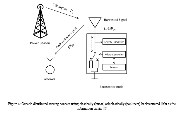
The end-to-end path length variation along the fibre set up to interact with the physical parameter field is measured by the interferometer. There are numerous ways that light can interact with the environment outside of it, and some of these can be set up to allow the development of a probe that reveals a parameter field as a function of position along the fibre length. The term "distributed sensing" refers to a method that is exclusive to fiber-optic technologies. A time-domain reflectometer can be used to read very few electrical cables, but none have the robustness, adaptability, and precision of the fiber-optic model. In order to expose typically a temperature or strainfield, distributed sensing relies on backscatter and on modulating the backscattered radiation produced by an optical beam travelling forward. There have been three main backscattering techniques used.

The greatest signal of the three is generated by Rayleigh backscatter, however the intensity that is returned is essentially a reflection of the intensity that arrived at the scattering site. Rayleigh backscattering devices must therefore control this intensity via a secondary mechanism. An offset frequency spectrum caused by brillouin scatter is directly related to the fiber's acoustic phonon spectrum. A measurement of the offset spectrum effectively generates a frequency that is dependent on the acoustic velocity in the optical fibre and the wavelength of the illumination source, which can then be stimulated by the illuminating optical beam. Considering that the former results from the latter, which in turn depends on temperature and strain. Ramanscatter measures the temperature at the scattering site by probing the optical phonon spectrum, for a thorough explanation of these interaction mechanisms, [10], [11]–[13].
The fundamental concept of distributed sensing was understood in the late 1970s [12], and the Raman distributed temperature probe was quickly mentioned [13]. A decade later [14], when the first Raman temperature probes were starting to appear commercially, the potential of Brillouin became significant. One of the most effective instruments provided by fiber-optic sensor technology is distributed sensing. It makes it possible to take special measures that are not possible with competing technologies. However, a complicated specialised and hence expensive piece of equipment, an optical time domain reflectometer (OTDR) designed to detect time variable Brillouin or Raman spectra, distributed sensing has found its niches despite this very important characteristics.
A. Multiplexing Systems
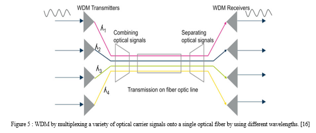
With the extremely small bandwidths required by sensing applications, optical systems have very good signal-to-noise ratio potential at the typical power levels involved in optical fibre transmission. Additionally, the signal-to-noise ratio only drops as the square root of power if the receiver power is below the shot noise limit. These straightforward discoveries led to the idea of multiplexing sensor arrays, which has been around for quite some time [15], and the concept of distributing this power among a number of sensors. A variety of topologies based on ladders, stars, and their combinations are possible for connecting the sensors. Additionally, multiplexing plays a significant role in Bragg grating technology (see below). However, up to 128 components can be usefully configured into a single array and fed from a single optical system, even with highly lossy sensors, like gas cells [16].

B. Fiber Bragg Garting (FBG)
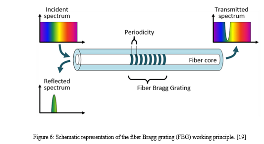
Midway during the same incredibly fruitful era, in the mid-1970s, the photorefractive effect in optical fibres was first discovered [17].Periodic structures can be created along the core of an optical fibre using the photorefractive effect, and these periodic structures (Fig. 7) serve as highly selective optical filters. The period of the grating, which in turn could be altered by temperature and phase excursions that alter the optical path length within the grating structure, determines the wavelength of reflection. Fibre Bragg gratings are a broad topic that mostly has communications-related uses for components like wavelength tuning and stabilisation structures and optical filters. A decade or so after the gratings were first created by dire cting opposing beams along the fibre, side illumination techniques utilising ultraviolet lasers gave the requisite freedom in defining the periodic structure [18].
Fibre Bragg gratings can be sequentially written down a single fibre in the context of sensors, and they can also be constructed to reflect light in several wavelength bands. As a result, a linear array of, for instance, 16 gratings can offer 16 distinct sensing points, each of which can be uniquely recognised using a spectral slicing technique. The period of each grating can then be determined by precisely measuring the wavelength in the reflected spectrum, typically using a stabilised reference. The optical route length affects this periodicity, which provides a clue as to the combined temperature and strain fields. The linear array of Bragg gratings can function as a multiplexed strain gauge array in an environment where the temperature is constant (or compensated for by other factors).But this is a unique array in certain ways. It may be attached to or implanted in a wide range of host materials, is incredibly small, and does not require distinct wires to connect to each strain measuring site. In the past ten years or more, bragg gratings have undergone substantial investigation as strain gauge components, and today they are likely the most widely discussed fibre sensor technology.
An optical fiber core refractive index is periodically modulated by an FBG. A FBG is frequently pictured as a barcode-like design with over 20,000 stripes imprinted over a fibre length of 10 millimetres.Depending on the periodicity of the grating, the periodic pattern in the fibre (i.e., FBG) reflects a certain wavelength of light. The reflected wavelength will shift if the periodicity is altered, for example, by lengthening the fibre near the FBG.Such an FBG is frequently employed in tough situations where traditional (electrical) sensors fail and is used to monitor many kinds of physical characteristics, such as temperature, pressure, and strain.

Conclusion
Measurement of physical parameters like temperature, displacement, velocity, and strain in structures of any size or shape is one of the many uses for fibre optic sensors. monitoring the physical makeup of health in real time.historical structures, tunnels, dams, and buildings and bridges.Detecting partial discharges, using night vision cameras, electronic security systems, and calculating vehicle wheel loads. So far, applications for fibre optic sensors have been suggested. Using fibre optic sensors for long-distance communication has a number of benefits, such as small size, low weight, compactness, high sensitivity, wide bandwidth, etc. The greatest usage of fibre optic as a sensor is made possible by all of these features.
References
[1] J. Hecht, City of Light. Oxford, U.K.: Oxford Univ. Press, 1999. [2] C. K. Kao and G. Hockham, “Dielectric fiber surface waveguides for optical frequencies,” Proc. IEE, vol. 113, pp. 1151–1158, July 1966. [3] J. C. Simon and E. Spitz, “Propagation guidée de lumière coherente,” Commun. à la Societé Française de Physique, vol. 24, no. 2, pp. 149–169, 1963. [4] R. B. Dyott and J. R. Stern, “Group delay in glass fiber waveguides,” in IEE Conf. Trunk Telecommunications by Guided Waves, London, U.K., Sept.-Oct. 1970, pp. 176–181. [5] C. Menadier, C. Kissinger, and H. Adkins, “The fotonic sensor,” Instru- ments and Control Systems, vol. 40, p. 114, 1967 [6] E. Snitzer, “Apparatus for controlling the propagation characteristics of coherent light within an optical fiber,” U.S. Patent 3 625589, Dec. 7, 1971 [7] https://www.elprocus.com/diffrent-types-of-fiber-optic-sensors/ [8] https://soundcloud.com/mopvi0magpo/intensity-modulated-fiber-optic-sensors-pdf-11-better [9] https://arxiv.org/pdf/1711.07277.pdf [10] B. Culshaw, Optical Fiber Sensing and Signal Processing. Stevenage, U.K.: Peregrinus, 1984. [11] B. Culshaw and J. P. Dakin, Eds., Optical Fiber Sensors. Norwood, MA: Artech, 1988, 1989, 1996, 1997, vol. 1–4 [12] E. Udd, Fiber Optic Sensors. New York: Wiley, 1990. [13] R. Willsch and R. T. Kersten, Eds., Fiber Optic Sensors. ser. SPIE Mile- stone. Bellingham, WA: SPIE, 1995, vol. MS108 [14] A. J. Rogers, “POTDR: A technique for the measurement of field distri- butions,” Appl. Opt., vol. 20, pp. 1060–1074, 1981. [15] M. C. Farries and A. J. Rogers, “Distributed sending using stimulated Raman interaction in a monomode optical fiber,” in Proc. 1st Optical Fiber Sensors Conf., London, U.K., 1983, pp. 121–133. [16] https://community.fs.com/blog/fiber-optic-transmission-multiplexing-technique.html [17] A. D. Kersey and A. Dandridge, “Distributed and multiplexed optical fiber sensors,” in Proc. 5th Optical Fiber Sensors Conf., 1988, pp. 60–72. [18] B. Culshaw, G. Stewart, C. Tandy, and D. Moodie, “Fiber optic tech- niques for methane gas detection-from detection concept to system re- alization,” Sensors and Actuators B Chemical, vol. 51, pp. 25–37, 1998. [19] https://hittech.com/en/portfolio-posts/noria-the-fiber-bragg-grating-manufacturing-solution/
Copyright
Copyright © 2023 Muhammad Arif Bin Jalil. This is an open access article distributed under the Creative Commons Attribution License, which permits unrestricted use, distribution, and reproduction in any medium, provided the original work is properly cited.

Download Paper
Paper Id : IJRASET54823
Publish Date : 2023-07-17
ISSN : 2321-9653
Publisher Name : IJRASET
DOI Link : Click Here
 Submit Paper Online

