Ijraset Journal For Research in Applied Science and Engineering Technology
- Home / Ijraset
- On This Page
- Abstract
- Introduction
- Conclusion
- References
- Copyright
A Comprehensive Study on DC to DC Converter Using M-Type Resonant Switching Topology
Authors: Dr. N. Ismayil Kani, Dr. B. V. Manikandan
DOI Link: https://doi.org/10.22214/ijraset.2025.66684
Certificate: View Certificate
Abstract
Advanced topologies for DC to DC converters have been required due to the growing need for small and highly efficient power conversion systems. An M-Type resonant switching topology, which provides notable increases in efficiency, switching losses, and electromagnetic interference (EMI) mitigation, is thoroughly analyzed and implemented in this study. The suggested design improves overall system performance by reducing power consumption during transitions by utilizing zero-current switching (ZCS) and zero-voltage switching (ZVS) approaches. To examine the resonant behavior of the circuit and determine design settings for important parts like the resonant components (capacitor and inductor), a thorough mathematical model is created.According to simulation studies, the M-Type architecture outperforms conventional hard-switching and other resonant designs, with efficiency levels above 95% under a range of load scenarios.
Introduction
I. INTRODUCTION
DC-DC converters are essential elements of modern power electronics, as they transform direct current (DC) from a specific voltage to another, facilitating efficient power distribution across many applications. Hard-switchiang techniques are frequently used in traditional converters, in which the power semiconductor devices handle high current and voltage concurrently while turning on and off. This method negatively impacts the overall performance of the system by producing electromagnetic interference (EMI) and significant switching losses.
Resonant switching topologies have been created to overcome these difficulties, allowing for soft-switching scenarios in which there is no voltage or current during the switching transitions. By drastically lowering switching losses and EMI, this technique improves power converter dependability and efficiency. The M-Type resonant switching topology is distinguished from the others by its special arrangement, in which the resonant capacitor is positioned directly across the switch. Zero Voltage Switching (ZVS) is made possible by this configuration, which enables the switch to function throughout transitions with less voltage stress.
The M-Type architecture has not been thoroughly investigated in DC-DC converter applications, despite its benefits. By offering a thorough examination of a DC-DC converter using the M-Type resonant switching topology, this study seeks to close this gap. The design concepts, modes of operation, and performance assessment using both simulation and experimental validation are the main topics of the study. The objective is to show that the M-Type resonant DC-DC converter is a feasible option for applications needing dependable and effective power conversion since it can achieve higher efficiency and lower EMI in comparison to traditional hard-switching converters. The M-type resonant switching topology is a useful strategy in contemporary DC-DC converter designs because it provides notable advantages in lowering switching losses, mitigating EMI, and increasing overall efficiency.
II. LITERATURE REVIEW
[1]A zero-voltage-switching (ZVS) quasi-resonant boost converter that utilizes a M-type switch is thoroughly analyzed, projected, and constructed in the 2007 publication "Digitally Controlled ZVS Quasi-Resonant Boost Converter with M-Type Switch" by Taufik, Luther, and Anwari. Critical voltage and current formulae for each of the converter's operating modes are derived by the authors. In order to verify their theoretical analysis, they also compare simulation findings with laboratory measurements and talk about hardware creation with digital control and computer simulations using OrCAD PSpice.[2] M-type switch is analyzed and designed in the paper "ZVS QR Boost Converter with Variable Input Voltage and Load" by Taufik, Luther, and Anwari (2008). Variable voltage sources and load conditions are the study's main focus. In order to develop converters that can retain high efficiency under a variety of operating settings, the study derives equations that describe the converter's behavior. Computer simulations and digitally controlled hardware development are used in the study to show how the converter performs and increases efficiency.
[3] In order to achieve a single switch, Saha and Islam's paper "Single-Switch Non-Isolated Resonant DC-DC Converter for Bipolar Output" (2023) presents a novel converter topology that combines the Cuk and SEPIC converters configuration. Applications needing dual-output voltages can benefit from this design's step-down/up conversion ratio and simplified gate drive mechanism. The usefulness of the combined topology is highlighted by the experimental findings, which show adequate regulation and acceptable efficiency.
[4] Taufik, Luther, and Anwari's work "A Review of DC-DC Resonant Converter Topologies and Control Techniques for Electric Vehicle Applications" (2023) offers a thorough analysis of resonant converter topologies and control approaches relevant to EV applications. It looks at different resonant converter designs, their modes of operation, modeling strategies, and control methods, providing engineers and researchers with useful information for putting effective power conversion systems in EVs into practice.
[5] The converter described in Zhang and Xu's (2019) paper "High-Efficiency Topology-Morphing Multi-Resonant DC–DC Converter" uses two auxiliary switches to adaptively change its topology according to operating conditions. This design shows the potential of topology morphing in resonant converter designs by efficiently reducing switching losses and increasing efficiency. Because of its excellent efficiency over a broad voltage gain range, the converter can be used in small-scale wind production systems, among other uses.
[6] In their 2023 work "Vehicle Onboard Chargers," Md. Tanvir Shahed and A.B.M.H. Rashid propose an enhanced design for an isolated bilateral resonant DC–DC converter intended especially for EV onboard chargers. This arrangement makes it possible for all of the inductances—aside from the capacitor—to be completely merged with the high-frequency transformer's mutual and leakage inductances, leading to a more efficient, cost-effective, and compact design.
[7] Zhang and Xu's (2019) work "A Review of DC-DC Resonant Converter Topologies and Control Techniques for Electric Vehicle Applications" offers a thorough analysis of resonant converter topologies and control approaches relevant to EV applications. [8,9] It looks at different resonant converter designs, their modes of operation, modeling strategies, and control methods, providing researchers and engineers with important information for putting effective power conversion systems in EVs into practice.
III. DC TO DC CONVERTER WITH M-TYPE RESONANT SWITCHING TOPOLOGY
A. Proposed Circuit
DC to DC Conversion The circuit schematic for the M-Type Resonant Switching Topology is displayed in the picture. The figure also displays the circuit diagram for the M-Type Resonant Switching Topology. This includes a DC power supply Vd, a switch S (usually an IGBT or MOSFET), a switch spanning a single resonant capacitor Cr and a parallel resonant inductor Lr connected, a diode D, a low frequency bandpass LC filter, and a load R.. One switch linked in parallel to one capacitor and one inductor connected in series makes up the M-Type Resonant Switching Topology.
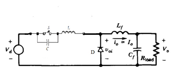
Fig. 1. Circuit diagram for DC to DC Converter Using M-Type Resonant Switching Topology
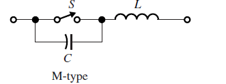
Fig. 2. Circuit diagram for M-Type Resonant Switching Topology
B. Operation of DC to DC Converter with M-Type Resonant Switching Topology
A resonant capacitor is positioned across the switch in the M-type resonant switching topology, a variation of the resonant converter, to accomplish zero-voltage switching (ZVS). This design's main goal is to increase converter efficiency and reduce switching losses, particularly at high switching frequencies. Resonant inductor (Lr), resonant capacitor (Cr), output filter (Lo and Co), diode (D), and switch (S) are the usual components of the topology.
Key Components
- Switch (S): Regulates the flow of power between the load and the input.
- Resonant Inductor (Lr): Contributes to the resonant tank circuit with Cr and stores energy.
- Resonant Capacitor (Cr): positioned across the switch, it improves in soft-switching by resonating with Lr.
Output filter (Lo, Co): Provides a stable DC to the load by smoothing the rectified DC output and minimizing ripple. - Diode (D): During particular operating phases, it guarantees unidirectional current flow.
- Load (RL): The external part that the converter sends its DC output to.
C . Operation Phases:
- Start-up / Pre-Resonance Phase (Switch Off)
- The input DC voltage (Vin) charges the resonant capacitor (Cr) when the switch (S) is off.
- The capacitor (Cr) charges through the inductor (Lr), the voltage across the switch (Vsw) begins to increase.
- When the capacitor (Cr) and inductor (Lr) combine to create a resonant tank circuit, the voltage across the switch rises to a point where ZVS is possible. The system is effectively in idle mode during this phase, with no current passing through the load.
- Zero Voltage Switching (ZVS) Transition (Switch On)
- The major characteristic of the M-type topology is that the switch (S) switches on when the voltage across the resonant capacitor (Cr) drops to zero, starting the resonant cycle.
- By avoiding the usual overlap between current and voltage during the switching operation, the switch minimizes power losses by turning on at the point where the voltage across it is zero (ZVS).
- One significant benefit over traditional hard-switched converters is the switch's smooth turn-on, which lessens component stress.
- Resonance Phase (Energy Transfer to Load)
- The inductor (Lr) and resonant capacitor (Cr) vibrate, effectively transmitting energy. Energy exchange between the inductor and the capacitor at a resonant frequency is guaranteed by the resonant tank.
- The switch stays on during this period, and energy is stored in the inductor before being subsequently delivered to the load via the output filter components.By keeping ZVS constant during this phase and reducing switching losses, the resonance mode operation contributes to high efficiency.
- Freewheeling Phase (Switch Off)
- The switch shuts off and the resonant tank starts to release stored energy once the energy has been transmitted to the load.
- The load receives current when the inductor (Lr) discharges through the diode (D). There are no notable switching losses during the turn-off since the voltage across the switch (Vsw) stays low.The diode (D) conducts during the freewheeling phase, giving the current a way to go from the inductor to the output filter and load.
- Zero Current Switching (ZCS) Recovery Phase (Switch On Again)
- Following the full discharge of the resonant capacitor (Cr), the converter goes into another cycle in which the switch is activated once again at zero current (ZCS).
- By preventing a high-current spike in the switch, the ZCS condition shields the converter from undue strain.
- With little switching loss, the resonant cycle repeats itself after the switch is turned on.
IV. FEATURES AND BENEFITS
- The M-type resonant converter uses zero-voltage switching (ZVS), which means that when the switch is turned on, there is no voltage across it. Because there are no abrupt voltage changes, switching losses are minimized.
- High Efficiency: with lowering power losses related to hard switching, the ZVS approach, when combined with soft-switching, greatly raises the converter's overall efficiency. This makes it perfect for uses where power efficiency is crucial, like power supplies for delicate electronics, electric cars, and renewable energy systems.
- Compact Design: The M-type converter's resonant nature enables it to function at higher frequencies, allowing for the use of fewer passive parts (capacitors and inducers), which ultimately results in a smaller converter overall.
- Increased Reliability: The soft-switching features help lessen voltage and current spikes, which lessens component thermal stresses and increases the converter's longevity.
- Low EMI: The converter reduces the high-frequency noise connected to traditional hard-switched converters due to ZVS operation. This makes it appropriate for uses like medical equipment and communication devices that are susceptible to electromagnetic interference (EMI).
V. APPLICATIONS OF M-TYPE RESONANT DC-DC CONVERTERS
- Electric Vehicles (EVs): M-type resonant converters are ideal for use in the powertrain and onboard charging systems of EVs because of their high efficiency and low heat output.
- Renewable Energy Systems: They are perfect for wind and solar (PV) systems, where maximizing energy harvest requires effective power conversion.
- Portable Electronics: M-type resonant converters enable small designs and steady power outputs for gadgets that run on batteries.
- High-Frequency Power Supplies: M-type converters work well with communications and data processing equipment because of their low switching losses, which make them ideal for high-frequency applications.
VI. SIMULATION RESULTS
DC to DC Converter Using M-Type Resonant Switching Topology matlab simulation diagram is as shown in figure
Input Voltage :100 V
Inductor : 50µH
Capacitor: 50µF
Resistance :10?
Resonan Inductor : 5µH
Resonan Capacitor: 5µF

Fig. 3. Simulation diagram for DC to DC Converter Using M-Type Resonant Switching Topology
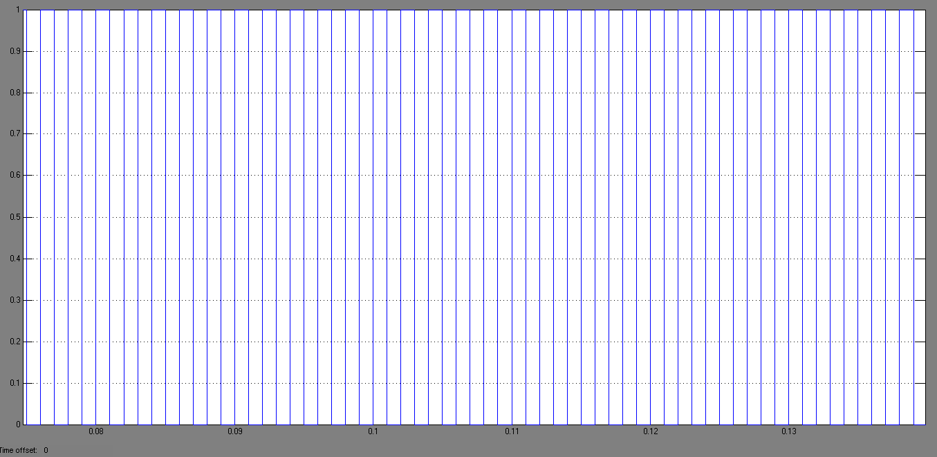 Fig. 4. Gate pulse for switch S
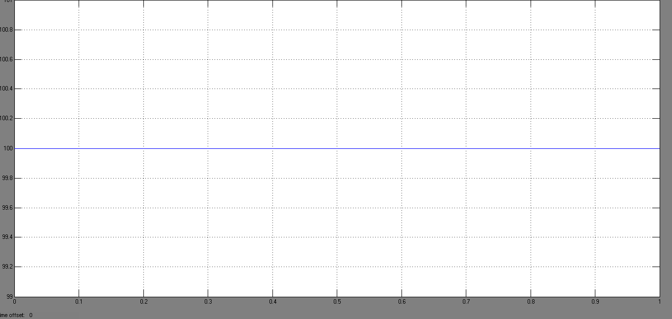 Fig. 5.Input votage
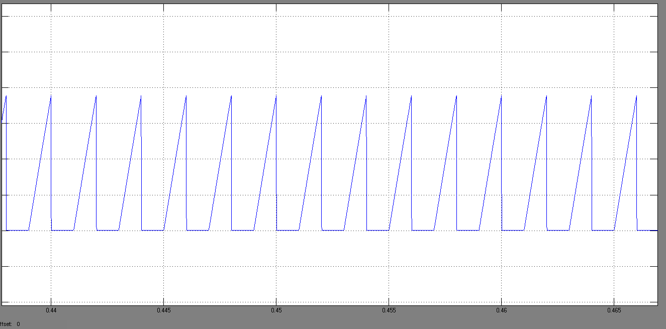 Fig. 6.Cr Capacitor Voltage
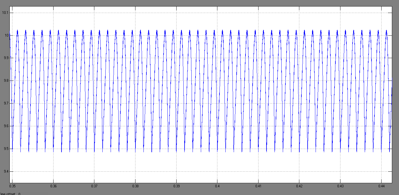 Fig. 7. Lr Resonan Inductor current
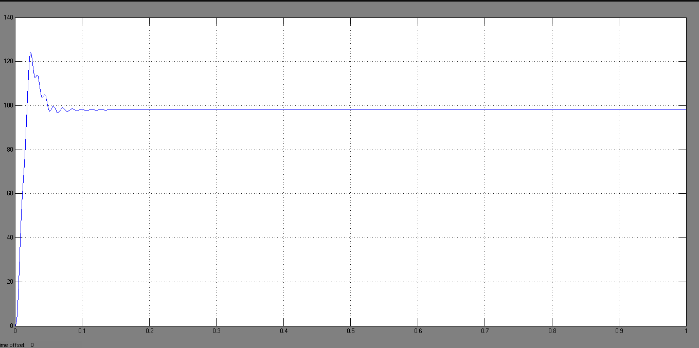 Fig. 8.Output voltage
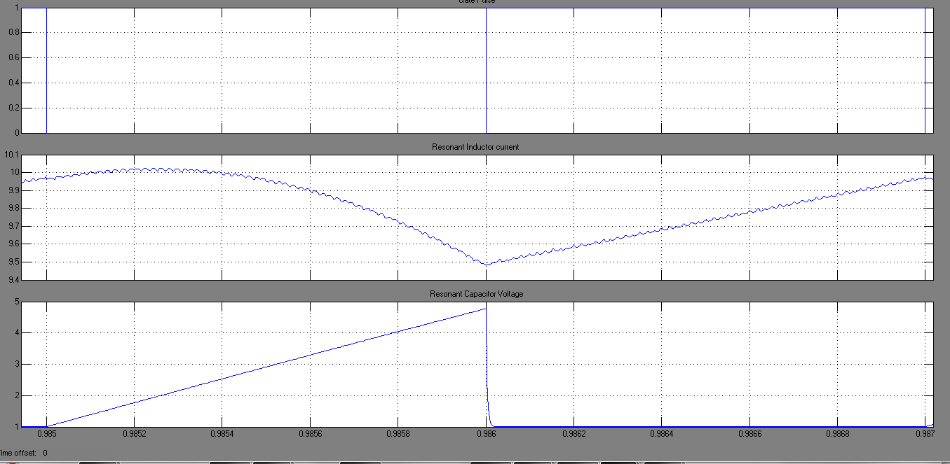 Fig. 9.Simulation output for Gate Pulse, Resonant inductor current, Resonan capacitor voltage.
Conclusion
In conclusion, there are a number of benefits to incorporating M-type resonant switching topology into DC-DC converters in contemporary power electronics. This topology makes zero-voltage switching (ZVS) possible by adding a resonant capacitor across the switch, which significantly lowers switching losses along with boosts on the whole efficiency. The M-type configuration\'s appropriateness for applications needing great efficiency and dependability is further enhanced by its capacity to reduce electromagnetic interference (EMI). Furthermore, the M-type topology\'s built-in soft-switching properties enable higher switching frequencies, which lower component sizes and increase power density. These benefits make M-type resonant switching DC-DC converters a desirable choice for a variety of applications, including renewable energy systems, electric vehicles, and portable electronics. In order to further develop performance and increase the range of applications for M-type resonant converters, future research and development in this field is anticipated to concentrate on improving control systems and investigating novel materials.
References
[1] Taufik, T., Luther, P., & Anwari, M. (2007). Digitally controlled ZVS quasi-resonant boost converter with M-type switch. Proceedings of the International Conference on Intelligent and Advanced Systems (ICIAS 2007). IEEE. [2] Taufik, T., Luther, P., & Anwari, M. (2008). ZVS QR boost converter with variable input voltage and load. Proceedings of the International Conference on Power Electronics and Drive Systems (PEDS 2008). IEEE. [3] Saha, T., & Islam, S. (2023). Single-Switch Non-Isolated Resonant DC-DC Converter for Bipolar Output. Electronics, 13(15), 8798. MDPI. [4] Saha, T., & Islam, S. (2023). A Review of DC-DC Resonant Converter Topologies and Control Techniques for Electric Vehicle Applications. Electronics, 13(15), 8798. MDPI. [5] Zhang, Y., & Xu, L. (2019). High-efficiency topology-morphing multi-resonant DC–DC converter. IET Power Electronics, 12(10), 2561–2569. IET. [6] Zhang, Y., & Xu, L. (2019). A Review of DC-DC Resonant Converter Topologies and Control Techniques for Electric Vehicle Applications. IET Power Electronics, 12(10), 2561–2569. IET. [7] Zhang, Y., & Xu, L. (2023). An Improved Topology of Isolated Bidirectional Resonant DC–DC Converter for Electric Vehicle Onboard Chargers. Mathematical Problems in Engineering, 2023, 2609168. Hindawi. [8] Saha, T. (2020). Soft-Switched Resonant DC-DC Converter in Underwater DC Power Distribution Systems. Master\'s Thesis, Utah State University. Utah State University. [9] Kazimierczuk, M. K. (2011). Resonant Power Converters. John Wiley & Sons
Copyright
Copyright © 2025 Dr. N. Ismayil Kani, Dr. B. V. Manikandan. This is an open access article distributed under the Creative Commons Attribution License, which permits unrestricted use, distribution, and reproduction in any medium, provided the original work is properly cited.

Download Paper
Paper Id : IJRASET66684
Publish Date : 2025-01-25
ISSN : 2321-9653
Publisher Name : IJRASET
DOI Link : Click Here
 Submit Paper Online

