Ijraset Journal For Research in Applied Science and Engineering Technology
- Home / Ijraset
- On This Page
- Abstract
- Introduction
- Conclusion
- References
- Copyright
A Conceptual Study of Wind Load With Different Types of Lateral Load Resisting Methods in 15-Storey Structure
Authors: Diksha Kamble, Dr. Mahesh V. Raut
DOI Link: https://doi.org/10.22214/ijraset.2024.62626
Certificate: View Certificate
Abstract
In order to strengthen rigidity and control the base deflection of a high-rise structure, stabilizers and trusses are typically used. A stabilizing layer on the building\'s roof efficiently fortifies the structure. Lateral stiffness is increased by each succeeding stabilizer layer, albeit less so than by the preceding stabilizer layer. The essential components in multi-storey buildings that can withstand shear forces are the shear walls. More efficient shear walls are required as building code requirements rise and tall structures and skyscrapers get taller. The ductility, energy dissipation capacity, and deformation capacity of conventional reinforced concrete shear walls are limited. In the field of structural engineering, a damper in a building is a device intended to lessen the impact of dynamic forces like seismic vibrations or oscillations caused by wind. These devices are necessary in tall or flexible constructions where excessive movement may cause structural damage or cause discomfort for the residents. In this research, we prepare four different cases of 15-storey structure. All modeling work performed in ETABS 2016. Material properties use concrete grade M-40 and steel grade Fe375 and Fe250. One case has shear walls on corners, second case have FVD damper on corners and last case have outrigger on corners. For design wind speed data use code IS: 875-(2015).
Introduction
I. INTRODUCTION
High structures' structural systems are made to withstand vertical gravity loads in addition to lateral loads brought on by wind and seismic activity. The components of a structural system are simply those meant to carry loads; identify the non-load-bearing components. The structure of a high-rise building is determined by the selection and placement of major structural components capable of withstanding various combinations of gravity and lateral loads. Skyscrapers need to have a stable way to withstand horizontal loads. To maximize bending stiffness, move the material as much as possible throughout the structure. Height has always attracted humanity, and throughout history, people have looked for connections to help them reach the heights. From the ancient pyramids to today's modern skyscrapers, majestic and colossal architecture has always symbolized civilization's strength and prosperity. Skyscrapers are now emblems of economic and political power. Humanity has demonstrated some competitiveness by claiming the world's highest structure. The ongoing pursuit of new objectives generates great opportunity for the building industry. From the initial temporary buildings to today’s enormous, highly efficient support structures, the construction industry has grown quickly. Recent developments in structural analysis and design software, along with advances in finite element methods, have led to the creation of many innovative architectural structures and forms. However, increasing the use of computer analysis will not solve the challenges facing the industry.
A. Wind Load
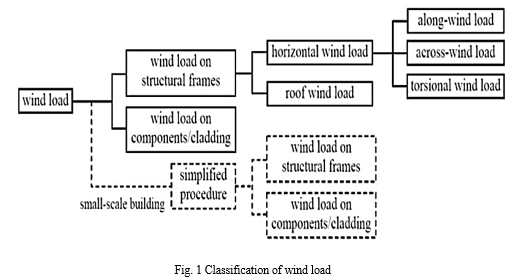
A building's specific structures are all subject to various loads, including the structure's own weight. Gravity is the reason for this. A similar load, known as overload, must be supported by the structure due to the weight of the people, furniture, furnishings, etc. In order for the structure to withstand loads, such as wind and earthquakes, it must do so. Buildings and other structures, as well as additional parts and finishing touches, must always be built to withstand wind loads. The term "wind load" refers to the force that the wind has on a structure. The entire surface of the structure is subject to this load. As the structure's height rises, the size of this load also grows. Compared to low-rise buildings, tall buildings are more vulnerable to wind effects. The force that the wind imposes on a structure is known as the wind load. The entire surface of the structure is subject to this load.
As the structure's height rises, the size of this load also grows. If have enough meteorological data, wind direction can be used to plan the orientation of each structural part. The type of land on which a particular building is constructed, it was determined by the following standards:
- Terrain Category 1
- Terrain Category 2
- Terrain Category 3
- Terrain Category 4
B. Shear wall
Shear walls are building components designed to resist lateral forces acting in a plane, usually brought on by wind or earthquakes. It can support loads due to the cantilever effect. Shear walls are hence vertical, force-resisting system components. In addition to the weight of the building and its occupants, lateral pressures from wind, earthquakes, and shifting loads can cause significant bending forces. These stresses may cause the building to slip or tear. You can maintain the contour of the frame and prevent joint rotation by strengthening it with internal joints or stiff walls. For high-rise structures meant to endure seismic effects and crosswinds, load-bearing walls are essential. It is strong and stiff enough to prevent lateral movement as well. The shape and positioning of the shear walls in the design have a considerable impact on the structure's performance.
C. Outrigger Structural System
The stabilization system connects perimeter supports to buildings with reinforced central frames or shear walls in order to significantly lessen structural deformation brought on by overturning moments and lateral displacement of the upper levels. When compared to a free cantilever, the use of a cantilever system can minimize the core overturning moment in high-rise building structures by up to 40%. It can also dramatically reduce deflections that are influenced by the relative stiffness of the core system and outriggers. (Zoppo 2008).). The center roll can be decreased by up to 60% when there are nearby mega columns to regulate flow and very tall towers. By applying a force to the core, this system reduces the rotation that makes the object fall. The stabilizers, straight walls, or indirect or "virtual" stabilizing effects of rolls of tape or film transfer these forces from the surrounding columns to the core.
D. Damper
A mechanical system that transfers seismic energy to specialized machinery that suffers damage or deformation during an earthquake. As a result, the constructed structure dissipates more energy and must withstand less seismic force. Dampers reduce the vibrations as they pass by, absorbing some of them. Seismic force is directed into a device under the lateral tension component by a properly set-up lateral tension system, and the device absorbs the energy.
An earthquake in this device transforms the mechanical energy of the structure into heat energy. This device enhances the structure's damping capabilities, which expands the damping structure's range of motion and lessens the force acting on the structural components.
- Viscous Damper (VD)
- Viscoelastic Dampers (VED)
- Friction damper
- Magnetorheological Damper (MR Damper)
- Pendulum Tuned Mass Damper or Vibration damper
II. PROBLEM STATEMENT
This work use 15-storey model consider lateral loading. The construction also has a shear wall, outrigger and FVD damper. The structure's storeys have 3m height each storeys. The entire building is vulnerable to wind loads and located in the first terrain category. The bending moment, shear force, joint displacement, and storey thrift of several structure shapes were compared and examined in ETABS software to incorporate variety into the study. The results were analyzed in ETABS software.
III. OBJECTIVES
- To Study the effect of Outriggers, shear wall and dampers Asymmetrical Buildings under Wind load on Lateral Displacement.
- To compare the lateral deflection and story drift in all cases of asymmetrical Building.
- To study the Static Response of Building i.e. Find out most Vulnerable Model & Suggest optimum lateral load resisting method of outrigger, damper and shear wall in high raise Building.
- To study importance of dynamic wind loading and methods for the same.
IV. RESEARCH METHODOLOGY
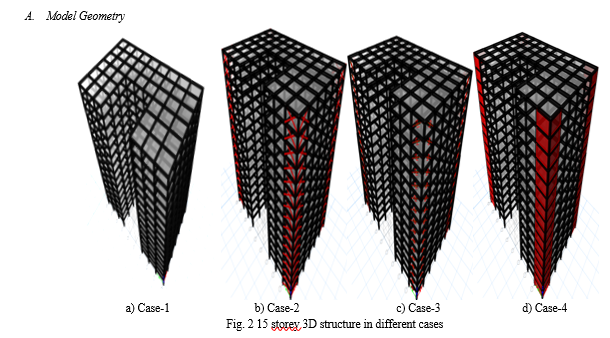
In this research, we prepare four different cases of 15-storey structure. All modeling work performed in ETABS 2016. Material properties use concrete grade M-40 and steel grade Fe375 and Fe250. One case has shear walls on corners, second case have FVD damper on corners and last case have outrigger on corners. For design wind speed data use code IS: 875-(2015).
Conclusion
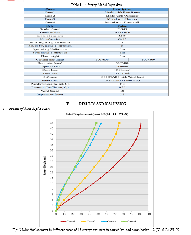
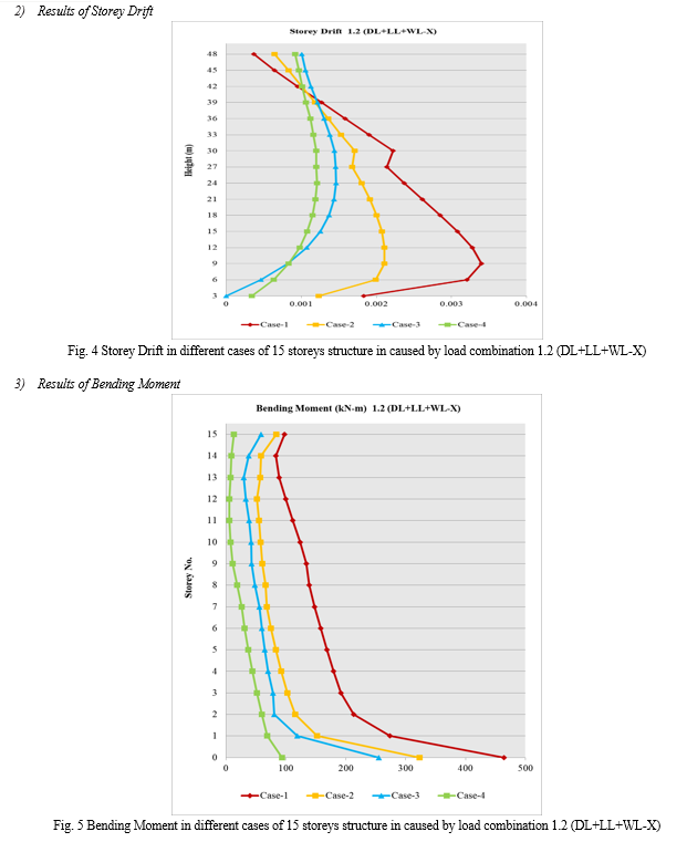
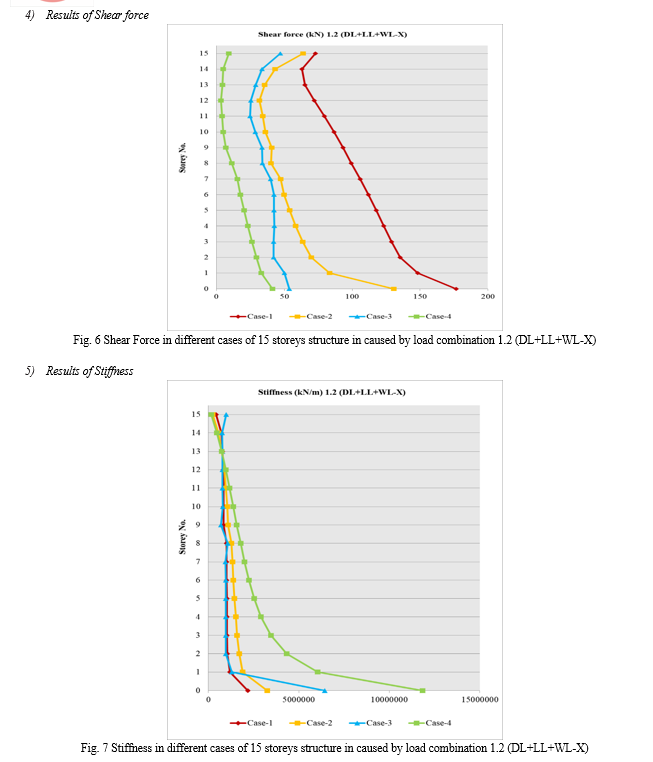
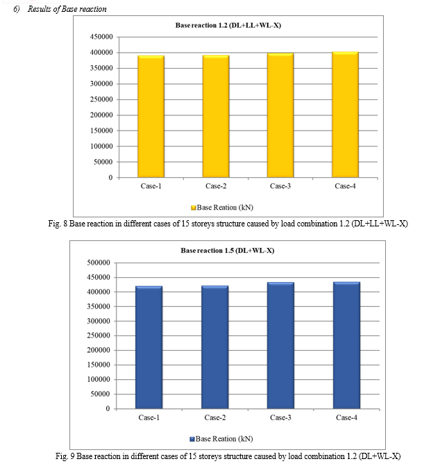
1) Maximum value of joint displacement in bare frame occurs due to load combination of 1.2(DL+LL+WL) is 101.16mm. This value of displacement reduced with application of outrigger is 75.52mm. With the help of damper reduced value of joint displacement was 53.61mm. And when consider shear wall in bare frame value of occurred joint displacement was 48.07mm. Maximum reduction in displaced was in case-4 and minimum change was in case-2. 2) Maximum value of storey drift in bare frame occurs due to load combination of 1.2(DL+LL+WL) is 0.00339. This value of drift reduced with application of outrigger is 0.00211. With the help of damper reduced value of drift was 0.001463. In addition, when consider shear wall in bare frame value of occurred drift was 0.00121. Maximum reduction in drift was in case-4 and minimum change was in case-3. 3) Maximum value of bending moment in bare frame occurs due to load combination of 1.2(DL+LL+WL) is 464.54kN-m. This value of bending moment reduced with application of outrigger is 323.36kN-m. With the help of damper reduced value of bending moment was 255.08kN-m. In addition, when consider shear wall in bare frame value of occurred bending moment was 93.67kN-m. Maximum reduction in bending moment was in case-4 and minimum change was in case-2. 4) Maximum value of shear force in bare frame occurs due to load combination of 1.2(DL+LL+WL) is 176.63kN. This value of shear force reduced with application of outrigger is 130.62kN. With the help of damper reduced value of shear force was 53.73kN. In addition, when consider shear wall in shear force value of occurred shear force was 41.19kN. Maximum reduction in shear force was in case-4 and minimum change was in case-2. 5) Stiffness (kN/m) 6) Maximum value of stiffness in bare frame occurs due to load combination of 1.2(DL+LL+WL) is 2192181kN/m. This value of stiffness increased with application of outrigger is 3250868kN/m. With the help of damper increased value of stiffness was 6426931kN/m. And when consider shear wall in stiffness value of occurred stiffness was 11841651kN/m. Maximum increment in stiffness was in case-4 and minimum change was in case-2. 7) Maximum value of base reaction in bare frame occurs due to load combination of 1.5(DL+WL-X) is 418814.31kN. This value of base reaction increased with application of outrigger is 419667.44kN. With the help of damper increased value of base reaction was 431370.49kN. And when consider shear wall in base reaction value of occurred base reaction was 433210.07kN. Maximum increment in base reaction was in case-4 and minimum change was in case-2. 8) Maximum value of base reaction in bare frame occurs due to load combination of 1.2(DL+LL+WL-X) is 389051.45kN. This value of base reaction increased with application of outrigger is 389733.951kN. With the help of damper increased value of base reaction was 396792.75kN. And when consider shear wall in base reaction value of occurred base reaction was 400568.05kN. Maximum increment in base reaction was in case-4 and minimum change was in case-2.
References
[1] GAO, Hui, et al. 2021. \"Optimum design of viscous inerter damper targeting multi-mode vibration mitigation of stay cables.\" Engineering Structures 226 111375. [2] Al Agha, Wesam, and Nambiappan Umamaheswari, 2021. \"Analytical study of irregular reinforced concrete building with shear wall and dual Framed-Shear wall system by using Equivalent Static and Response Spectrum Method.\" Materials Today: Proceedings 43: 2232-2241. [3] Varma, V. Naresh Kumar, and Uppuluri Praveen Kumar, 2021. \"Seismic response on multi-storied building having shear walls with and without openings.\" Materials Today: Proceedings 37: 801-805. [4] Azandariani, Mojtaba Gorji, Mohammad Ali Kafi, and Majid Gholhaki, 2021. \"Innovative hybrid linked-column steel plate shear wall (HLCS) system: Numerical and analytical approaches.\" Journal of Building Engineering 43: 102844. [5] amad, Shaik Akhil, and K. V. Pratap, 2021. \"Dynamic analysis of G+ 20 multi storied building by using shear walls in various locations for different seismic zones by using Etabs.\" Materials Today: Proceedings 43 (): 1043-1048 [6] Liu, Yanhui, et al, 2020. \"Experimental and numerical studies on the optimal design of tuned mass dampers for vibration control of high-rise structures.\" Engineering Structures 211- 110486. [7] Liu, Yang, et al, 2020. \"Spectrum-based pushover analysis for the quick seismic demand estimation of reinforced concrete shear walls.\" Structures. Vol. 27. Elsevier [8] Alhaddad, Wael, et al, 2020. \"Optimum design method for simplified model of outrigger and ladder systems in tall buildings using genetic algorithm.\" Structures. Vol. 28. Elsevier, [9] Petrini, Francesco, Agathoklis Giaralis, and Zixiao Wang, 2020. \"Optimal tuned mass-damper-inerter (TMDI) design in wind-excited tall buildings for occupants’ comfort serviceability performance and energy harvesting.\" Engineering Structures 204: 109904 [10] Pietrosanti, Daniele, Maurizio De Angelis, and Agathoklis Giaralis, 2020. \"Experimental study and numerical modeling of nonlinear dynamic response of SDOF system equipped with tuned mass damper inerter (TMDI) tested on shaking table under harmonic excitation.\" International Journal of Mechanical Sciences 184- 105762. [11] Wang, Qinhua, et al, 2020. \"Seismic response control of adjacent high-rise buildings linked by the Tuned Liquid Column Damper-Inerter (TLCDI).\" Engineering Structures 223: 111169. [12] Samadi, M., and N. Jahan, 2019. \"Determining the effective level of outrigger in preventing collapse of tall buildings by IDA with an alternative damage measure.\" Engineering Structures 191 -104-116. [13] Wang, Wei, et al, 2019. \"Experimental study of the hysteretic behaviour of corrugated steel plate shear walls and steel plate reinforced concrete composite shear walls.\" Journal of Constructional Steel Research 160-136-152. [14] Ahzhang, Jie, et al, 2007. \"Safety analysis of optimal outriggers location in high-rise building structures.\" Journal of Zhejiang University-Science 8.2- 264-269.
Copyright
Copyright © 2024 Diksha Kamble, Dr. Mahesh V. Raut. This is an open access article distributed under the Creative Commons Attribution License, which permits unrestricted use, distribution, and reproduction in any medium, provided the original work is properly cited.

Download Paper
Paper Id : IJRASET62626
Publish Date : 2024-05-24
ISSN : 2321-9653
Publisher Name : IJRASET
DOI Link : Click Here
 Submit Paper Online

