Ijraset Journal For Research in Applied Science and Engineering Technology
- Home / Ijraset
- On This Page
- Abstract
- Introduction
- Conclusion
- References
- Copyright
Study of Adhesive Bonded Joints between Metallic Plates and Composite Laminates
Authors: Prasad P, Sreenivasa Murthy B P, Thimmegowda M B
DOI Link: https://doi.org/10.22214/ijraset.2024.65948
Certificate: View Certificate
Abstract
Many researchers studied influences of various parameters on the failure behavior on the composites. One of the challenges in the analysis and design of bonded joints is the valuation of the stress and strain fields at the adhesive layer and adherents. The present investigation deals with the analysis of adhesively bonded dissimilar material single lap joints (SLJ) between mild steel and unidirectional carbon fibres reinforced polymer (CFRP) laminates. The primary objective of this study is to investigate the effects of various parameters, such as bonding strength, overlap length, adherend thickness, and adhesive thickness, on the failure load and failure mode of joints with dissimilar materials. Failure process, mode and strength of unidirectional composite to mild steel single lap adhesive bonded joints were investigated numerically by using finite element methods. Numerical methods based on finite element models can be very useful in describing the stress and strain responses for each load step. The SLJ specimens are done nonlinear analysis and predict the force -displacement and force- strains curves and conclusions regarding joint stiffness and strength are obtained for different cases of SLJ.
Introduction
I. INTRODUCTION
Many methods exist for bringing together similar or dissimilar structural materials, in terms of the joining technique utilized. Conventional mechanical joints, such as bolted, pinned or Riveted are preferred due to their simplicity and the disassembly ability that they offer for joining metal or composite materials. However, when a mechanical joint is loaded, local damage is induced at the fastener holes due to stress concentrations.
The use of adhesive bonded joints in load-bearing structures is of great interest to the aerospace, automotive industry and to machine tools modules development as [1]. Time and cost savings, high corrosion and fatigue resistance, crack retardance and good damping characteristics are the major advantages of these joints altering the geometry of a bonded joint will invariably cause changes in the stress and strain distribution.
The loads in a single lap joint are not co-linear, what produce a bending moment which causes the joint to rotate. This consequently exposes the adhesive layer into shear, and peeling stresses. The adherends are similarly at the same time subjected to tension and bending. It is quite possible that deformation of both of adhesive and adherend may become plastic, particularly in the highly stressed regions [2]. Research on SLJs has been conducted through experimental and/or numerical methods. Most researchers have assessed bonded joints with similar adherents [3-4]. On the other hand, a limited number of papers have been published regarding joints with dissimilar materials and in particular joints consisting of steel and composite adherents. Owens et al. [5, 6] studied composite-to-aluminium joints in terms of their stiffness behavior due to fractures. Seong et al. [7] investigated the effects of various parameters, such as bonding pressure, overlap length, adherent thickness and material type on the failure load and failure mode of joints with dissimilar materials.
Da et al. [8, 9] Structural adhesive bonding is gaining more and more the interest of researchers and design engineers due to the advantages it offers compared to mechanical joining techniques, particularly when it comes to joining dissimilar materials, e.g. composites to metals.
Engineering analysis of adhesive bonded joints to predict behavior up to failure using the finite element method and commercial FEA software is the focus of this study[10]. The specific joint chosen is unique since it has experimental results up to final failure.
II. MATERIALS
Three different materials have been considered for the fabrication of the adhesive joints, i.e. CFRP and steel for the substrates and a structural adhesive for the adhesive, orthotropic elastic properties of the CFRP adherents
|
E1(MPa) |
E2(MPa) |
E3(MPa) |
V12 |
V13 |
V23 |
G12(MPa) |
G13(MPa) |
G23(MPa) |
|
35000 |
3000 |
3000 |
0.35 |
0.3 |
0.3 |
2000 |
1500 |
1500 |
TABLE 1: Orthotropic properties for CFRP adherends
The material utilized for the metallic substrates was normal marine grade steel. The Young modulus of the steel material is equal to 170 GPA, the Poisson ratio is equal to 0.3 and the yield stress limit is equal to 180 MPa
For bonding the dissimilar substrates, a ductile and relatively stiff epoxy adhesive material, namely Araldite 2015 (Huntsman Container Corporation Ltd.), was utilized. Fig. 1 presents a typical tensile stress–strain curve measured from bulk adhesive Araldite 2015 coupons.
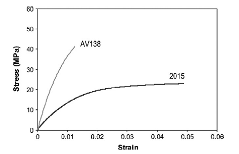
Fig. 1: stress strain curve for adhesives
This figure shows the ductile characteristic behavior of Araldite 2015 compared to the brittle behavior of AV138. This figure is necessary for investigations and justifications of the results provided in the numerical part of this work.
III. NUMERICAL MODELING AND METHODS
A. Geometry
Adhesive joints of CFRP and mild steel as adherend material and Araldite 2015 have been considered in this work. Basic single lap adhesive joint is represented in figure.

Fig. 2: Dimensions of the bonded joints
In adhesive bonding joint, the load is transmitted from one adherend to another adherend through the adhesive layer in the overlap region [1].
At small overlapping, bonded area is reduced. Joint is exposed to shear stresses induced with adherend moving and to small values of stresses caused by bending momentum. With increasing of load applied to lap joint, stresses can overcome the elastic limit values in adhesive/adherend interface.
By increasing of overlap length stresses through the overlapping region are decreased. Loading stresses in adherend can lead to elastic or elastic/plastic limit and even can match proportional limit of adherend caused by transmitted load through the overlapping region
TABLE 2: Dimensions of the SLJ cases considered for the numerical study
|
Case |
Tc (mm) |
Ts(mm) |
Lt(mm) |
La(mm) |
Lo(mm) |
Ta(mm) |
W(mm) |
|
SLJ-1 |
7.89 |
8 |
40 |
75 |
75 |
0.52 |
23.76 |
|
SLJ-2 |
8.60 |
8 |
40 |
75 |
75 |
0.89 |
24 |
|
SLJ-3 |
9.29 |
5 |
40 |
75 |
75 |
0.84 |
23.89 |
|
SLJ-4 |
9.99 |
5 |
40 |
75 |
25 |
0.51 |
23.83 |
B. Finite Element Type
PLANE182 is used for 2-D modelling of solid structures. The element can be used as either a plane element (plane stress, plane strain or generalized plane strain) or an axisymmetric element. It is defined by four nodes having two degrees of freedom at each node: translations in the nodal x and y directions. The element has plasticity, hyper elasticity, stress stiffening, large deflection, and large strain capabilities. It also has mixed formulation capability for simulating deformations of nearly incompressible elastoplastic materials, and fully incompressible hyperplastic materials.
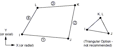
Fig. 3: Element type
C. Numerical Modelling
Numerically implementation of the experimental obtained results. The commercial FEA code ANSYS version 15 has been used in numerical analysis. Fig.4 shows the geometry of single lap bonded lap was numerically modelled by using of plane models with two-dimensional 4-node isoperimetric finite elements (PLANE182) which discretize geometry of models with triangular or/and rectangular elements Simulations of axial stretching of the bonded joints have been carried out under the boundary conditions.
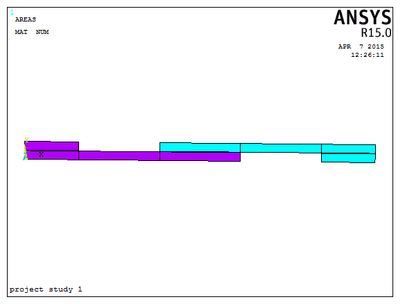
Fig .4: Modelling of the object
D. FE Meshing
To divide the number of elements in the object meshing used.in this finite element mapped meshing are used to discretise the model. The total number of elements used 1100 and the total number of nodes used 1221.Fig.5 shows the how meshing done to the FE model.
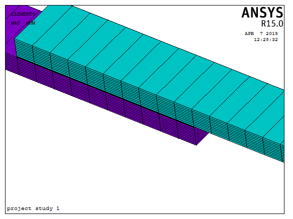
Fig.5: Finite element meshing object
E. F E Boundary Conditions
1) Loading
A longitudinal force of 25kn is applied for 75mm overlap region and 10kn load apply to 25mm overlap region to determination of the failure load on the free surfaces of a single lap adhesively bonded joint. The material nonlinearity is used to do nonlinear analyses of the adhesive bonded single lap joint.
2) Boundary Conditions
In this condition the one end of the cfrp has been fixed in all degrees of freedom, the other end of the mild steel has been applied the load, at the same time both the ends some nodes has been fixed in UY direction due to gripping to the specimen are as shown in fig.6.
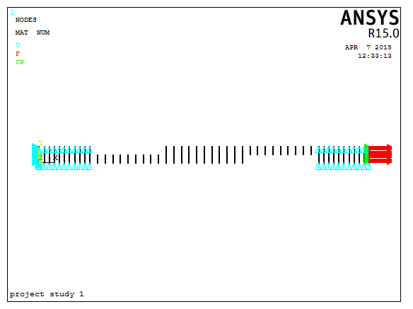
Fig.6: Applied boundary condition to the models
IV. RESULTS AND DISCUSSION
The following fig shows the finite element analysis results are obtain according to the four cases. The results are showed X direction displacement, Vonmises stress and the final failure mode shapes of the four cases used.
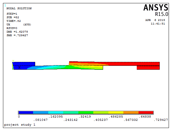
Fig. 7: Displacement in UX direction for case 1
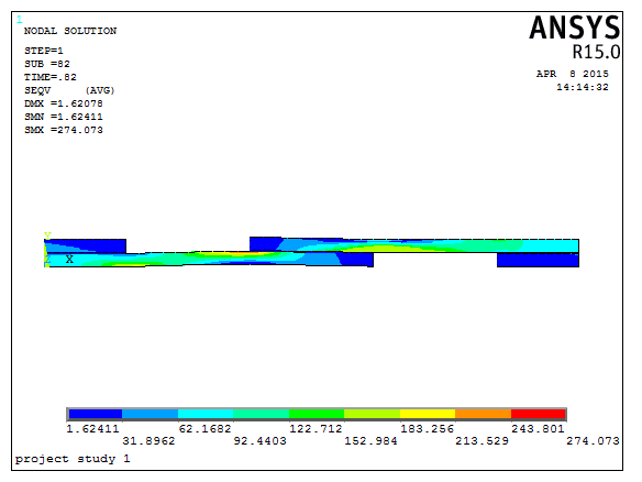
Fig. 8: Vonmises stress distribution for case 1
Fig.7 indicates the maximum displacement is 0.729mm with the applied failure load is 20.5kn and fig.8 shows the Vonmises stress distribution for the case1 condition we can observe that the maximum stress distribution at the adherents nearer to adhesive. The results are case1 as similar to the case 2 condition.
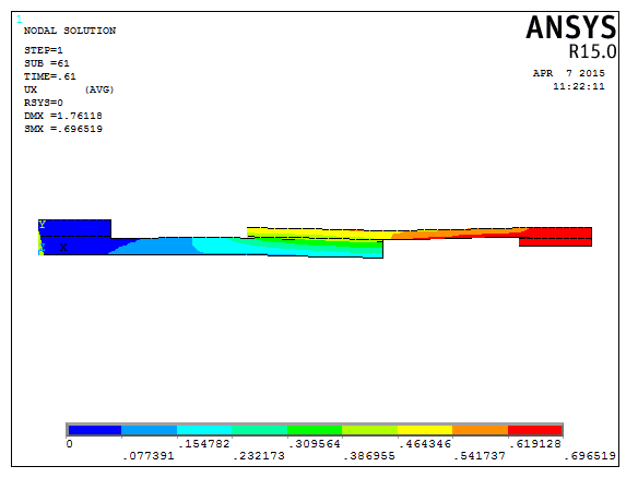
Fig .9: Displacement in UX direction for case 3
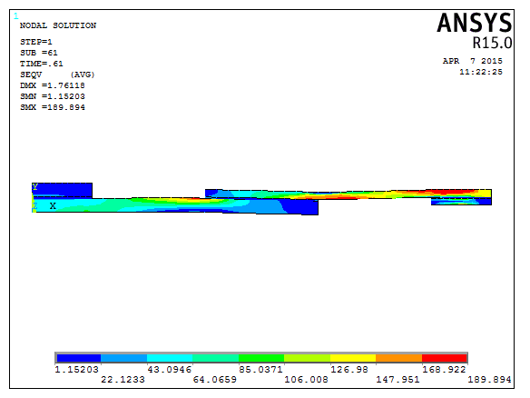
Fig .10: Vonmises stress distribution for case 3
Fig.9 and fig.10 shows the displacement variation in Ux direction and the hoe stress distribution are done in the bonded joints for case 3 conditions.
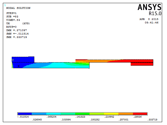
Fig. 11: Displacement in UX direction for case 4
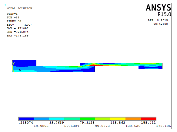
Fig. 12: Vonmises stress distribution for case 4
Fig.11 shows the displacement variation in Ux direction for the lap length region 25mm and the stress distribution is very high in the mild steel region for the 25mm lap region are shown in the above fig.12
A. Failure Mode Shapes
. 
Fig. 13: Shows the failure mode for case 1 (Similar to case 2)

Fig. 14: Shows the failure mode for case 3

Fig .15: Shows the failure mode for case 4
Fig.13 shows the failure mode shape for case 1 and case 2 conditions. We can see the maximum bending was more in the composite region. Fig.14 shows the failure mode shapes of case 3,in this we can see that the steel plate is less strength and fail at the load 15.75KN.fig.15 shows the failure modes shape of the short overlap 25mm region.
TABLE 3: RESULTS FOR ALL THE CASES
|
cases |
Displacement in X in mm |
Vonmises stress in MPa |
Strain in X direction |
Shear stress In MPa |
Failure load In KN |
|
SLJ 1 |
0.729 |
274.07 |
0.0191 |
13.84 |
20.5 |
|
SLJ 2 |
0.694 |
270.19 |
0.0077 |
13.84 |
18 |
|
SLJ 3 |
0.696 |
189.89 |
0.0278 |
33 |
15.75 |
|
SLJ 4 |
0.333 |
178.18 |
0.0038 |
24.85 |
8.3 |
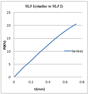
Fig. 16: load v/s displacement curve for case 1
Fig.16 shows the curve for load v/s displacement for the case 1(similar to case 2), the curve is non-liner and fail at load 20.75kn at corresponding displacement 0.72mm. Similarly fig.17 shows for case 3 conditions and fig.18 show the graph between load v/s displacements for small overlap region. The results are obtained similar to the experimental results K.N. Anyfantis[1].
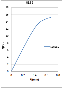
Fig. 17: load v/s displacement curve for case 3
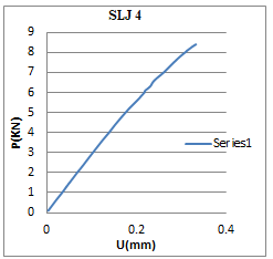
Fig. 18: load v/s displacement curve for case 4
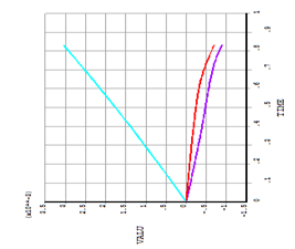
Fig .19: Time v/s strain curve for case 1(similar to case 2)
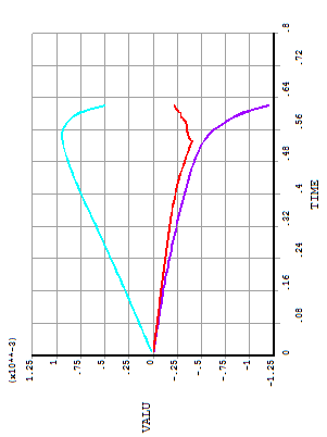
Fig .20: Time v/s strain curve for case3
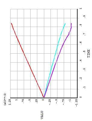
Fig .21: Time v/s strain curve for case 4
Three strain gauges are used in the three particular conditions 77.5 mm distance strain gauge 1,lap end region in the CFRP used strain gauge 2 and lap end region at mild steel used strain gauge 3 from the origin. Measured the strain value the particular distance and plot the graph between time and strain measure value at three points. The fig.19 shows the graph between time v/s strain for case 1 and 2 conditions, in the first measured strain value is 3.1e-3 ,second point measure strain value is -0.7e-3 and the third point measured strain value is-0.9e-3.simillar kind of graph are plotted in fig .20 for case 3 and fig. 21 for case 4 conditions. Time for case 1, 2, and 3 is converting for failure load multiply maximum applied load i.e. 25KN.similarly for case 3 to converting time to load multiple maximum applied loads to use in nonlinear analysis that is 10KN. Example for case 1, 25KN used maximum apply load ,the failure time is 0.84.to convert for failure load multiple time with maximum apply load we get failure load that is 20.75KN is the failure load for case1.similary can find the further cases. The results are obtained similar to the experimental results K.N. Anyfantis[1].
Conclusion
This work is of an integrated study of CFRP-to steel adhesively bonded joints with thick adherents. An effort was made herein for simulating the four tested single lap joint cases, by utilizing advanced numerical tools by using ansys. In the four tested cases are in terms of exploring the loading and failure response of the adhesive layer and adherent materials with different thickness and different overlap condition. The failure loads of the joints with 25 mm and 75 mm overlap length were predicted with a load was very less in the 25mm overlap region and the failure load was high in the 75 mm overlap regions. In the long overlap region strain at first point is 3.2e-3 and the small case region that is in 25 mm overlap region the strain 1.23e-3.It has been concluded that the adhesive layer of the short overlap joints enters plasticity in a more uniform manner compared to the long overlap joints and the joint stiffness is more in the longer overlap length, a fact that justifies the differences in the failure loads.
References
[1] K.N. Anyfantis, N.G. Tsouvalis, “Experimental parametric study of single-lap adhesive joints between dissimilar materials”, eccm15 – 15th European conference on composite materials, Venice, Italy, 24-28 June 2012. [2] Lee, Y.-H., Lim, D.-W., Choi, J.-H., Kweon, J.-H., Yoon, M.-K. “Failure load evaluation and prediction of hybrid composite double lap joints”. Composite Structures, 92, pp. 2916-2926 (2010). [3] Kairouz, K.C., Matthews, F.L. “Strength and failure modes of bonded single-lap joints between cross-ply adherends”. Composites, 24, pp. 475–484 (1993). [4] Kim, K.S., Yoo, J.S., Yi, Y.M., Kim, C.G. “Failure mode and strength of uni –directional Composite single-lap bonded joints with different bonding methods”. Composite Structures, 72, pp. 477–485 (2006). [5] Owens, J.F.P., Lee-Sullivan, P., “Stiffness behavior due to fracture in adhesively bonded Composite-to-aluminium joints I. Theoretical model”. International Journal of Adhesion and Adhesives, 20, pp. 39-45 (2000). [6] Owens, J.F.P., Lee-Sullivan, P., “Stiffness behavior due to fracture in adhesively bonded Composite-to-aluminium joints II. Experimental”. International Journal of Adhesion and Adhesives, 20, pp. 47-58 (2000). [7] Seong, M.-S., Kim, T.-H., Nguyen, K.-H., Kweon, J.-H., Choi, J.-H., “A parametric study on the failure of bonded single-lap joints of carbon composite and aluminium”. Composite Structures, 86, pp. 135-145 (2008) [8] da Silva LFM, das Neves PJC, Adams RD, Spelt JK. “Analytical models of adhesively bonded joints – Part I: literature survey”. Int J Adhes 2009; 29:319–30. [9] da Silva LFM, das Neves PJC, Adams RD, Wang A, Spelt JK. “Analytical models of adhesively bonded joints – Part II: comparative study”. Int J Adhes 2009; 29:331–41. [10] Quasaremin, M., Ricotta, M. “Life prediction of bonded joints in composite materials”. International Journal of Fatigue, 28, pp. 1166–1176 (2006).
Copyright
Copyright © 2024 Prasad P, Sreenivasa Murthy B P, Thimmegowda M B. This is an open access article distributed under the Creative Commons Attribution License, which permits unrestricted use, distribution, and reproduction in any medium, provided the original work is properly cited.

Download Paper
Paper Id : IJRASET65948
Publish Date : 2024-12-16
ISSN : 2321-9653
Publisher Name : IJRASET
DOI Link : Click Here
 Submit Paper Online

