

Ijraset Journal For Research in Applied Science and Engineering Technology
Advanced Wireless EV Charging Station
Authors: Mr. B Tharun Kumar, Mr. Yaski Vamshi, Mr. M. Teja, Dr. J. Mohan
DOI Link: https://doi.org/10.22214/ijraset.2025.66400
Certificate: View Certificate
Abstract
In this paper a new technique is claimed the wireless Electric Vehicle charging station system. In this process, it was tested and verified the battery charger application of electric vehicle. Wireless Electric Vehicle charging Technologies that are developed in the field of sustainable transportation involves the field of wirelessly charging electric vehicles. This process which is inductive power transfer, sends energy from a charging pad to the electric vehicle\'s battery without supplying any wires or adapters. Benefits of the wireless charging include convenience since there is no need for physical connectors, it reduces the wear and tear on the charging ports; safety that eliminates exposure of environmental elements which can cause electric shock. The E-V charging of battery through charger and wire is convenient, hazardous and expensive. The present gasoline and petrol engine technology vehicles contributes to air and noise pollution, in addition contribute to the greenhouse gases. This paper presents the wireless charging Station of battery for EV, by method of inductive coupling. In this part here, there\'s a driving circuit was used between the transmitter coil & receiver coil where a MOSFET was used and controlled the switching operation. This thus, ensures that in the transmitter coil circuit was turned on and off whenever the vehicle is present, and whenever the vehicle is absent. The Station achieves 67% efficiency level with safety, reliability, low maintenance and a long product life time.
Introduction
I. INTRODUCTION
There are numerous problems in the world that do not need electricity. In daily life, electric power is necessary for various applications like mobile devices, laptops, cameras, sensors, bionic implants, satellites, and oil platforms. Nikola Tesla proposed the idea of wireless power transmission in 1821, and the first wireless power transfer station for illumination was demonstrated by Tesla. Sometimes using too many wires into a small power outlet could be inconvenient and hazardous. The first electric vehicle was almost commercially introduced by Thomas Parker in 1884. Until 1859 there were no rechargeable batteries for storing electrical energy; Gaston Plant invented the lead-acid battery and reduced the drawback. Electric vehicles are very popular in many countries; they come in different sizes: small, large bus-sized, car-sized two-wheelers, and small electric bicycles. Electric vehicles are like regular vehicle; however, they contain a different motor, and that motor is an electric motor. For an electric vehicle to move, it uses the energy source of an electric motor, which is a battery. New forms of rechargeable batteries are now available; this is used since it is smaller compared to conventional lead-acid battery; it is able to hold a greater capacity of energy being stored, and it weighs less. The process of charging is cumbersome for an ordinary electric vehicle, since for charging the battery, the user could be a user is often frustrating for them.
that is directly connected to the vehicle, or the battery is sometimes removed for charging purposes, however utilizing the inductive power technology makes this difficult charging situation to be easier understands.
Inductive power transfer method involves transmitting power wirelessly through magnetic coupling from a static transmitter to one or more movable followable secondary receiver. There is a considerable air gap between the primary source and the secondary load; it might be single-phase or three phases depending upon the power requirement. Essentially, a WPT Station comprises: matching circuit, transmitter (primary coil), receiver (secondary coil), microcontroller, sensors, battery, and power supply. If the magnetic structure of the coil, IPT Station may be either distributed topology even it can be lumped topology. The AC current is generated in the transmitter coil from the power supply at a low frequency Fr. There are circumstances where one primary coil can couple to more than one secondary coil, under their magnetic fields. The AC frequency current in the primary coil is now creating a strong and controllable magnetic field for WPT. All these concerns are not related on IPT Station therefore Station will be suitable for environmental condition and maintenance free. Advances of power electronics technology has founded many new applications based on IPT Station, wireless power supply for professional instrument, for wireless battery charging for electric vehicle and over wide air gaps, specifically when dealing with material handling. whereas, are all high-power applications of the IPT Station concept, examples of the low power application of IPT Station are medical implants, cell phone, lighting. If the mutual coupling of the IPT Station is normally ignored. And the receiver coil is completely electrically isolated with transmitter coil, and the receiver moves to follow a long track of transmitter in every direction.
Benefits of IPT Station listed below.
- The station is safe
- The Station has low maintenance.
- It has long product life.
- Energy wastage is overcome.
- Magnetic field radiation problem is overcome
II. LITERATURE SURVEY
The concept of wireless power transfer by IPT method is discovered from many years and now gaining more. Literature survey is prime component during this dissertation, an exhaustive review on the subject area has been done as given below.
Hui Zhi (Zak) Beh has proposed a Double-Coupled Station (DCS) for wirelessly charging the batteries of electric vehicles using Inductive Power Transfer (IPT) technology. The concept utilizes a switch, called an intermediary coupler, between its primary coil and secondary pickup, which doubles its coupling distance and improves the efficiency by taking all of the losses on each one of its "switching" branches.
Jesus sallan is describing a design process in which a design factor is selected to either choose parameters for a (coreless) IPT session, for example optimum number of coil, compensation capacitors, and a frequency. If done appropriately, the design factor may lead to the ability to produce high power while operating very efficiently.
Akshya K. Swain presents a bidirectional IPT Station on which the wireless transfer of power is made easy between the two sides separated by air gap, via weak magnetic coupling. Creating a precise mathematical model makes it more complicated and some difficulty within the design and/or control of the station. A dynamic model of the IPT Station by state variables was produced. This model is a common model used for steady state and transient analysis of IPT Stations, or design of controllers.
Dukju Ahn and Songcheol Hong states that for the IPT Station design, the application of the concept of repeaters within the model improves the distance of power transfer between transmitter coil and receiver coil. The position of the repeater between the transmitter and receiver coil is obtained safely. The same amount of power is delivered, however the efficiencies are significantly different in the two scenarios with repeating, that is if the repeating is closest to the transmitter, better efficiency is achieved.
Using a gap as the distance to be had in mind, for example a gap of 10-15 cm between the road surface and bottom of the electric vehicle, is a wide gap for some vehicles (in particular trucks or buses). To repeat the IP station method while minimizing the gap, some methods are needed enhance charge distance through repeaters.
III. NEED OF WIRELESS POWER TRANSFER STATION
In the future, the fuel like coal, petrol, diesel is vanishes because these are nonrenewable source of energy. The transportation Station will have limitations in future. Therefore we go for the electric vehicle for transportation purpose. Due to the existing gasoline and petrol engine technology vehicles greenhouse gases are increases. Plug-in Electric Vehicles are implemented to achieve environmental friendly transportation and reduced some extent of greenhouse gas. Usage of PEV is increased nowadays with some battery related problems such as slower charging rate, low energy storage capacity, size and weight. So, a new technology is required for battery related problems as well as for the development of EVs. Therefore, many consumers have not accepted PEVs on a priority basis due to charging related problems. To minimize battery related issues, greenhouse gases, and to resolve the magnetic field radiation problem, the concept of WPT Station is developed. Many charging stations are built up on the side of road, since the users travel farther distance by recharging their electric vehicle.
As a result, it was unnecessary to carry a large-capacity battery, so a compact one replaced it, as it weighed less.
Charging Stations of Stationary IPT is quite simple in that EVs can be charged without wires, while the vehicles are parked at home, or stay at the office parking lot. These IPT Stations do not require to have any charger to assimilate the energy to charge EVs. Every-time, providing reliability and comfort. Among them, DSM Station would cause the lowest cost to implement at one deployment of the extending roads or intersection. Costliest parts are power supply and track, and installation cost of a DSM Station is still high. Some design difficulties of DSM Station need to be sacrifice to achieve those features and advantages of DSM stations. Therefore, phenomenal growth has occured in the last two decades, on the IPT method, that started from industrial applications, and in the future design on realistic designs on stationary and dynamic methods, can achieve the challenge of sustainably power electric vehicles (EVs). The implementation of EVs, with the IPT method, produces high value not only from consumers point of view, but from sustainable energized consumption perspective., Once the concept of WPT able EV's that driving via Vehicle to Grid can be arrangements and become a additional device method to distributed energy generation and energy storage.
IV. PRAPOSED METHOD
Fig. 1 depicts the block diagram of proposed wireless power supply Station for charging the battery of electric vehicle. It has three components namely: Transmitter in order to develop an AC signal for it which is to be transferred wirelessly, transmitting and receiving coil for power transfer and receiver to convert the received AC signal to DC voltage in order to charge the battery of the electric vehicle. The objective of developed Station is to build a wireless power supply Station prototype capable of charging the battery of an electric vehicle while saving the wastage of power.
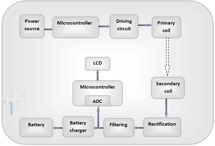
Fig. 1. Block diagram of WPT Station.
The basic block diagram of the wireless power transfer Station includes two sections. They are, the transmitter section or primary coil and the receiver or secondary coil section. It provides 230V, 50Hz AC signal. Micro-controller the MOSFET switch is applied to manage the AC current fed into transmitting coil. An AC current passes through the transmitting coil the creates magnetic field and passes through the receiving coil. According to Faradays law of electromagnetic induction the voltage or EMF induced by the magnetic field passes through the receiving coil. This induced voltage generates current through the secondary winding. The rectifier converts the AC signal to DC signal. Voltage regulator is used to get a regulated DC signal for electric vehicle.
In the proposed Station, Battery at 12V DC is given to AC converter. The provided signal into AC converter gets converted to AC signal. The AC signal is then passed into transmitting coil, again the magnetic field is generated. The power is transferred from the transmitter coil to the receiving coil using the magnetic field. The AC signal is also rectified to DC in the receiving coil again. The rectified voltage is stored in battery. Rechargeable battery is therefore used in proposed Station. In the conventional Station, once the power or supply is generated the whole setup will turn on, the magnetic field is produced, voltage is induced and the wireless transmission takes place. For charging purpose, when the vehicle is present in the system, a signal is sent from IR sensor to the MOSFET switch to turn on the current to the transmitter coil. The MOSFET switch then turns on the current to the transmitter coil to start the charging process to the electric vehicle. When the vehicles presence is detected by IR sensor the MOSFET switch shuts off current to the transmitter coil therefore stopping the process of wireless power transfer. The use of micro-controller on the system helps to stop the worries of magnetic field radiation and energy waste as well.
Fig. 2 Image of the prototype WPT Station with arrangement of transmitter track coil and in vehicle placement of receiver coil and LCD display Explanation of each of the Station components is mentioned below.
B. Coil Design
The transmitter coil and the receiver coil are central to the overall design of the Station. If the size of the coils is the same; and they are configured in the same manner, the coils will get tightly coupled. In this Station, a configuration that allows for tight coupling, and the transfer of power over a small distance, is used to provide high efficiency for electric vehicle (EV) applications. The two coils in the Station are tuned to the same frequency. The coils are made from electrically conductive copper tubing, which is 16cm in diameter. Each coil has 48 turns, and 56uH inductance. The two coils have an airgap of 6cm.
C. Microcontroller PIC16F877
The PIC16F877 is a microcontroller with 40 pins and 8 bits, being virtually the best microcontroller from Microchip. Due to its high quality, low price, and availability, the PIC16F877 microcontroller is mainly used for experimental purposes and modern applications. The PIC16F877 microcontroller offers the following features:
•368 bytes of RAM
•256 bytes of EEPROM data memory
•Two 8 bit and one 16 bit timer
•Five input output ports
•Two serial communication ports (MSSP, USART)
•8 channel 10 bit ADC
•2 CCP modules.
In developed Station PIC16F877 microcontroller is used because of following reasons.
It has inbuilt ADC which is required to sense battery voltage and convert it in digital format.
- It requires low power supply.
- It is less expensive than other microcontrollers.
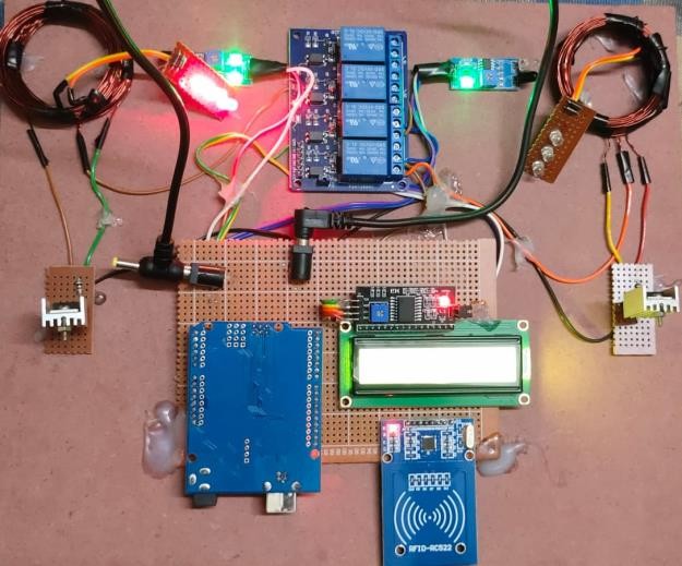
Fig. 2. Photograph of the prototype WPT Station, including transmitter and receiver coil
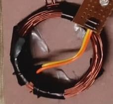
Fig: Coil design
D. Rectifier
Rectifier is used to convert the AC signal into DC signal for charging the battery but the DC output is varying. In many power supply circuits, the bridge rectifier is used. In the proposed Statio single phase full wave bridge rectifier is used to convert received AC voltage into DC. A full wave bridge rectifier is used because it has a high efficiency of 81.2%.
E. LCD
In the Station 16x2 LCD is used to display current activity of project. 16x2 LCD means there are two lines in LCD and each line display 16 characters. LCD provides the following features because of that it is used in developedStation:
-
- It is display numbers, characters and graphics.
- The LCD consist of refreshing controller to reduce the overhead of the CPU
- Programming of such LCD is easy
F. Voltage Regulator 7805 -
It cancels ripple and provides a stable voltage. Using a 7805- voltage regulator reduces high DC voltages to 5V DC volts. Usually, an IC7805 regulator will operate in the range of 7.2V to 35V with maximum operating efficiency at 7.2V. If the voltage is maintained at a voltage above 7.2V energy is simply lost in the form of heat. The site uses 7805 series regulator in order to convert the voltage high DC voltage supply to a regulated 5V DC.
V. EXPERIMENTAL RESULT
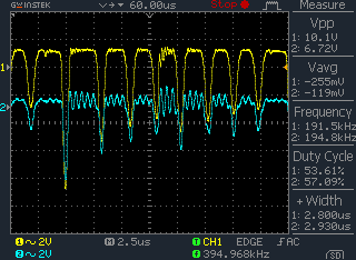
By switching the wireless power transfer station On/Off, the transmitting section transmits power wirelessly to the receiving section. In the transmitting section, AC converter has been applied 240 KHZ to wireless transmit power. In the receiving section power is used to recharge the battery and run an electric vehicle. Fig. 3 demonstrates the capture of the results of the proposed Station using the digital storage oscilloscope. Figs.3.1 and 3.2 waveforms demonstrate what the transmitter coil and receiving coil look like respectively. Once the process can be initiated, the transmitting coil transmits 10.1 V, at a frequency of 191.5 KHz, however after transiting some loss the receiving coil receives 6.72V at a differing frequency of 194.8kHz. the Results of the setup in the NB-2 calculated electric vehicle demonstrate good correlation, and efficiency can be calculated based on the total input power versus power used by EV car to charge the battery.
Efficiency=EV car using power
Total input power
Table I. result of wirelwss EV Station As the distance increases the received voltage decreases,It means as the distance increases efficiency also decreases. The total Station efficiency 67% is achieved by considering all classes and power supply. Fig. 4: Receives the Voltage on LCD
|
Transmitter coil voltage |
10 V |
|
Receiver coil voltage |
6.72V |
|
Distance between coil |
6cm |
shows the input power
G shows the EV using power
Fig 3.voltage of transmitter and receiving coil

Fig. 4. LCD shows receiving voltage
Conclusion
An inductive power transfer (IPT) is an example of a high- power wireless EV charging Station that utilizes the kinetic energy storage based on the inductive nature of the vehicle. The power transfer (MOSFET) that works as a switch is situated directly between the transmitting coil and the receiving coil with the micro-controller. Power is turned on by the transmitter circuit when the car is near and turned off if the vehicle departs, through the cordless power transfer system. The use of the proposed ac switch, which is responsible for the control of the Station power transfer, is the solution for preventing the energy wastage issues. Also, this is the method of radiation prevention. The rel various parts, such as the inverter, rectifier, filter, the transmitter, etc., are integrated in the inductive power transfer Station using a battery charger application of electric vehicle to realize the concept proof. A prototype of wireless charging EV Station is developed with efficiency level of 67 % and results are verified. The Station is designed to be safe, reliable, and long-lasting.
References
[1] Hui Zhi (Zak) Beh, Grant A. Covic, and John T. Boys “Wireless Fleet Charging Station for Electric Bicycles” IEEE journal of emerging and selected topics in power electronics, vol. 3, no. 1, march 2015. [2] H. H. Wu, J. T. Boys, and G. A. Covic, “An AC processing pickup for IPT Stations,” IEEE Trans. Power Electron., vol.25, no. 5, pp. 1275– 1284, May 2010. [3] K. Swain, M. J. Neath, U. K. Madawala, and D. J. Thrima with ana, “A dynamic multivariable state-space model for bidirectional inductive power transfer Stations,” IEEE Trans. Power Electron., vol. 27, no. 11, [4] pp. 4772– 4780, Nov. 2012. [5] C.-S. Wang, O. H. Stielau, and G. A. Covic, “Design considerations for a contactless electric vehicle battery charger,” IEEE Trans. Ind. Electron.,vol. 52, no. 5, pp. 1308–1314, Oct. 2005. [6] H. Hao, G. A. Covic, and J. T. Boys, “An approximate dynamic model of LCL-T based inductive power transfer power supplies,” IEEE Trans. Power Electron., doi: 10.1109/TPEL.2013.2293138. [7] PIC datasheet 2001 Microchip Technology, Inc. [8] IC 7805 datasheet 1998 Korea Electronic co. Ltd. [9] Wei -Ting Chen, R. A. Chinga, and Shahei Yoshida, “A 36W wireless power transfer Station with 82 percent efficiency for LED Lighting Application,”Trans. of the Japan institute of Electronics., vol. 6, no. 1, oct 2013. [10] D.M. Vilathgamuwa and J.P.K. Sampath “WirelessPower Transfer (WPT) for Electric Vehicles (EVs)-Present and Future Trends”Power Stations, DOI 10.1007/978-981-287-299-9_2, Springer Science+Business Media Singapore 2015. [11] A. Dukju and H. Songcheol, “A study on magnetic field repeater inwireless power transfer,” IEEE Trans. Ind. Electron., vol. 60, no. 1,pp. 360–371, Jan. 2013.
Copyright
Copyright © 2025 Mr. B Tharun Kumar, Mr. Yaski Vamshi, Mr. M. Teja, Dr. J. Mohan. This is an open access article distributed under the Creative Commons Attribution License, which permits unrestricted use, distribution, and reproduction in any medium, provided the original work is properly cited.

Download Paper
Paper Id : IJRASET66400
Publish Date : 2025-01-08
ISSN : 2321-9653
Publisher Name : IJRASET
DOI Link : Click Here
 Submit Paper Online