

Ijraset Journal For Research in Applied Science and Engineering Technology
Study Performance on AL-SI Alloy Bearing with SAE20W40 as Lubricants in Constant Speed and Varying Load Condition
Authors: Prasad P, Sreenivasa Murthy B P, Varun K S
DOI Link: https://doi.org/10.22214/ijraset.2024.66116
Certificate: View Certificate
Abstract
In this present work an attempt is made to study the pressure distribution of Aluminium-Silicon alloy as bearing material and also load carrying capacity is evaluated ,From the results obtain it has been observed that, the maximum pressure distribution is obtained for SAE20W40 grade oil with constant speed varying load condition. So in the present work it has been selected to carry out the study on performance of the Aluminium-Silicon alloy bearing by considering the SAE20W40 grade lubricating oils as lubricating mediums and study has been carried out to find out the maximum pressure distribution by using a journal bearing test rig The Al-Si alloy as test bearing and test lubricating oils SAE20W40 is run at constant speed and varying load conditions (Example; 150N, 300rpm). It is made to run for 1hour to take maximum pressure value at angular rotation of 180?. Sensor mounted on the bellow of the housing which gives the pressure readings and the data are transferred to the WINDOWS DUCOM 2010 software, extract condition of the bearings and gives the pressure distribution graphs as shown outcomes. Observe that pressure distribution is very less in 300 rpm with 150 N load is 75 Kpa and maximum pressure distribution is at 700 Rpm with load capacity 700 N is 1738 Kpa.
Introduction
I. INTRODUCRTION
Bearing is used to carry radial loads of transmitting members in motion is called as journal bearing. Journal bearings are considered as essential components of all the rotating machinery. In the field of turbo machine components and automobile suspension system requires bearing to operate at high performances like higher speed, higher load and higher temperature conditions.
From the reviews of literature it has been observe that various researchers carried out analysis particularly on copper based alloys published information related to Aluminium-Silicon alloy as a bearing material and relevant information are not available. So in the present work it has been selected to carry out the study on performance of the Aluminium-Silicon alloy bearing.
Non-Ferrous alloys like bronze, brass, aluminum have a wide range of applications in the heavily loaded and lightly loaded bearings. Aluminium bearings were developed to provide bearings to carry heavy loads. Aluminium-Silicon alloys is using widely in the industries at different fields. The Aluminium-Silicon alloy is the strongest alloy among the aluminium alloys. Features of Aluminium-Silicon alloy as bearing materials are having high thermal conductivity, corrosion resistance and high fatigue strength. [1]
A. Selection of Lubricants
Journal bearing is needed to fill with oil cooling to remove the dust particles from bearing surface. Oil lubricants are used in high speed journal bearings either than using grease. Pumping systems are used to pressurize the oil. Oil ports are given on the bearings to supply the oil along the surfaces of bearing. Depending on the load carrying capacity, speed of bearing and oil temperature the viscosities grades are selected, in revolution per minute the bearing speed is taken. If the speed of bearing is higher the oil viscosity should be lower. If the oil temperature is high then high viscosity of oil is required.
The high pressure and low pressure zones, which are created within the oil on each side of the area of minimum film thickness, can cause oil cavitation in these bearings. Cavitation is a result of expansion of dissolved air or vapors in the low-pressure zone of the bearing. The resulting bubble causes damage, as it flows through the high pressure portion of the bearing. [5]
B. Oil film Development in the Bearing
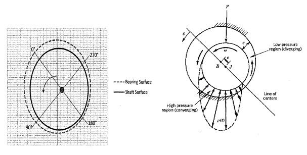
Fig: 1 Oil film development in the bearing [5]
The oil drawn into converging section the relative motion takes place, oil is forced out and the pressure increases. The developed oil film is shown in Figure 2.5 pressure generated on the bearing. The oil in converging section gets thinner and develops positive pressure which can support shaft load. Oil at diverging section gets thicker and develops negative pressure will tends to cavity in diverging section. [5]
II. SCOPE AND OBJECTIVE
From the literature it has been observed that, these various researchers have made an attempt to study the behavior of journal bearings with different lubricants particularly for copper based alloys, information related to aluminium based alloys is not available. Based on this an effort is made to study the performance on Aluminium- Silicon bearing by using SAE20W40 grade oils as lubricants with the following objectives.
- To find out the maximum pressure distribution of Journal Bearing Test Rig by using SAE20W40 grade oil as lubricant.
- To estimate oil viscosity for different bearing loads and speeds.
- To determine the load carrying capacity and frictional force of journal bearing.
- To evaluate stresses analytically to validate life of bearing.
- To carry out comparative study of performance of lubricants
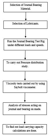
III. METHODOLOGY ADOPTED
A. General Description of Journal Bearing Test Rig (JBTR)
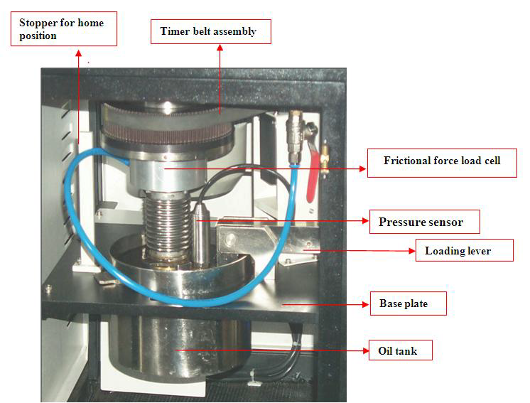
Fig 2: JBTR
Continuous lubrication is provided by oil sump is placed at base plate bottom as shown in Figure 2 . Bearing and journal surface are separate by oil film when bearing is in home position. Software Winducom is interfaced with system to plot pressure distribution v/s bearing circumferential angle in degrees. Trails are carried out and the note downs the maximum pressure and maximum angle which is saved in the hard drive of computer. By using this software we can compare two or more pressure distribution results. [9]
B. Lubricants used for Experiment
Table 3.1: Shows the SAE20W40 Grade oil description. [10]
|
SAE GRADE |
20W40 |
|
Kinematic viscosity@100?c,cSt |
15.5 |
|
Viscosity Index,Min. |
110 |
|
Flash point,COC,?c,Min |
200 |
|
Pour point,?c,Max |
(-)21 |
SAE20W40 Grade Oil: This oil is high performance engine oil and procured by Servo oil and lubricants having the description followed by Table 3.1. The term “W” stands for winter grade
IV. RESULT AND DISSCUSIONS
A. Al- Si alloy bearing using SAE20W40 constant speed and varying load condition
To find the pressure distribution of SAE20W40 oils in the Al-Si alloy bearing used constant speed and variations of load method. In this method four tests are carried out, in each test speed is constant and varying the loads. The following table indicates the four tests are carried out by fixing the speed and varying the loads of bearing.
Table 4.1: SAE20W40 constant speed and varying loads conditions.
|
Test |
Applied constant speeds of bearing in rpm |
Varying load in Newton(N) |
|||
|
1 |
300 |
150 |
400 |
550 |
700 |
|
2 |
500 |
150 |
400 |
550 |
700 |
|
3 |
700 |
150 |
400 |
550 |
700 |
|
4 |
1000 |
150 |
400 |
550 |
700 |
The above four test results of each test are briefly discussed in the following points.
Graph represents pressure distribution of constant speed journal bearing with various conditions of loads using SAE20W40 oil. The speed is fixed to 300 rpm and noted the value of bearing pressure at a different load condition of 150N, 400N, 550N and 700N are shown in the Figure 4.1. By fixing the speed has constant 300 rpm the maximum pressure is held at the bearing load of maximum applied load 700N, the minimum pressure is obtained at the minimum applied load of 150N.maximum value of pressure is 1440.8 KPa at an angle of 80 degree and minimum value of pressure noted at the load of 150N corresponding pressure value is 179.2 KPa. For 400N and 550 N applied load value of pressure is 868.6 KPa, 820.4 KPa.
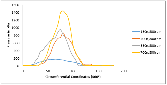
Figure 4.1: Pressure distribution vs. Circumferential Coordinates (360o) graph for constant speed of 300 rpm
Pressure distribution of constant speed journal bearing with various conditions of loads using SAE20W40 oil is as shown in the Figure 4.2. The speed is fixed to 500 rpm and noted the value of bearing pressure at a different load condition of 150N, 400N, 550N and 700N. Certain angle of bearing the pressure value is horizontal then suddenly pressure value is increase. The maximum value of pressure is noted at the load of 700 N corresponding value of pressure is 1737.3 KPa and the value of angle is 80 degree. The minimum pressure value is noted at the less load of 150 N, the value minimum pressure is 227.5 KPa at angle of 80 degree. In this case of study the value of pressure is noted for remaining load of 400N and 550N bearing maximum pressure is 916.9 KPa and 1268.5 KPa.
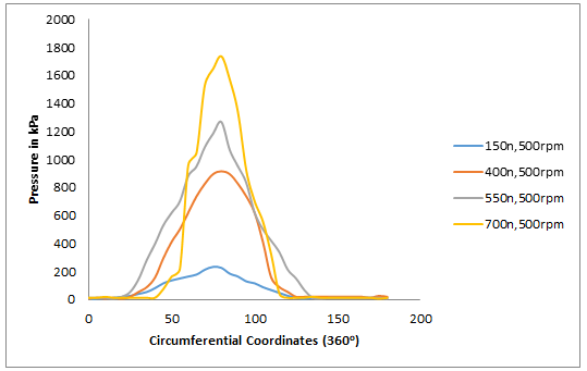
Figure 4.2: Pressure distribution vs. Circumferential Coordinates (360o) graph for constant speed of 500 rpm
Graph represents the pressure distribution of constant speed journal bearing with various conditions of loads using SAE20W40 oil, the speed is fixed to 700 rpm and noted the value of bearing pressure at a different load condition of 150N, 400N, 550N and 700N are as shown in Figure 4.3. The pressure value is low at minimum applied load to bearing and the pressure value is maximum at applying maximum value of load, the following results are obtain the constant speed of 700 rpm. The maximum pressure is 1737.3 KPa at an angle of 80 degree, the minimum value of pressure is 234.4 KPa at a bearing angle of 75 degree. The remaining load of 400 N applied, maximum pressure noted 792.8 KPa and 550N load applied maximum pressure is 1041.2 KPa.
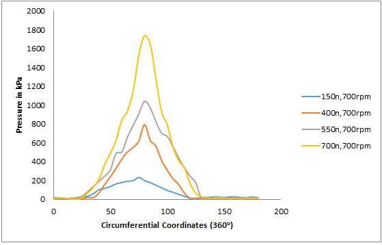
Figure 4.3: Pressure distribution vs. Circumferential Coordinates (360o) graph for constant speed of 700 rpm
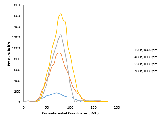
Figure 4.4: Pressure distribution vs. Circumferential Coordinates (360o) graph for constant speed of 1000 rpm
Represent graph of pressure distribution of constant speed journal bearing with various conditions of loads using SAE20W40 oil Figure 4.4. The speed is fixed to 1000 rpm and noted the value of bearing pressure at a different load condition of 150N, 400N, 550N and 700N. By fixing the speed has constant 1000 rpm the maximum pressure is held at the bearing load of maximum applied load 700N, the minimum pressure is obtained at the minimum applied load of 150N. Maximum value of pressure is 1633.9 KPa at an angle of 80 degree and, minimum value of pressure noted at the load of 150N corresponding pressure value is 165.5 KPa at a bearing angle of 75 degree. For 400N and 550 N applied load value of pressure is 910 KPa, 1247.8 KPa.
B. Complete result tabulations of SAE20W40 constant speed and varying loads conditions
Table 4.2: Constant speed varying loads of SAE20W40 all four cases test results
|
Oil SAE20W40 Constant Speed |
150 N load |
400 N load |
550 N load |
700 N load |
|
|
Speed 300 rpm
|
Max pressure in KPa
|
179.2 |
868.6 |
951.4 |
1440.8 |
|
Circumferential Coordinates(360o) In degree |
65 |
80 |
75 |
80 |
|
|
Speed 500 rpm |
Max pressure in KPa
|
227.5 |
916.9 |
1268.5 |
1737.3 |
|
Circumferential Coordinates(360o) In degree |
80 |
80 |
80 |
80 |
|
|
Speed 700 rpm
|
Max pressure in KPa
|
234.4 |
792.8 |
1041.2 |
1737.3 |
|
Circumferential Coordinates(360o) In degree |
75 |
80 |
80 |
80 |
|
|
Speed 1000 rpm
|
Max pressure in KPa
|
144.8 |
910 |
1247.8 |
1633.8 |
|
Circumferential Coordinates(360o) In degree |
80 |
75 |
80 |
80 |
|
C. Viscosity Calculations of SAE20W40 Grade Oil
To measure the viscosity of the oils after physical test the Say bolt viscometer is used:
1) Say Bolt Viscometer Observation And Calculations
T= Temperature of oil at equilibrium condition in ?
S= Say bolts second
M1= Mass of empty flask in grams
M2= Mass of flask with oil I grams
ρ= Density of oil in Kgm3
=MassofoilVolumeofoil=(m1-m2)×10-660000
γ=Kinematicviscosity= 0.226S-180S×10-6inm2secS<100secEq.1
γ=Kinematicviscosity= 0.226S-180S×10-6inm2secS>100secEq.2
2) For SAE20W40 Grade oil
Table 3.3: Tabular column for SAE20W40 grade oil test.
|
Sl No |
Temperature in ? |
S in sec |
M1 in grams |
M2 in grams |
γinm2sec |
|
1 |
35 |
75 |
14 |
60.05 |
7.64×10⁻⁶
|


γ=0.226×75-18075×10-6
=(16.95-2.4)×10-6
γ=7.64×10⁻⁶m2sec
Conclusion
The following conclusions are drawn from the analysis of data obtained by conducting detailed experimentation. In the results found by the graphs at all operating conditions of constant speed and varying load conditions. The maximum pressure distribution of SAE20W40 grade oil is 1744kPa. The maximum pressure occurs during the 160°-170° it shows the sudden rise in pressure the short duration it shows the stability of the bearing. The maximum pressure distribution is occurred where thickness of oil film is minimum and pressure at zero in a cavitation zone. The load and speed on bearing increases the pressure distribution. It is observed that variation of pressure in SAE20W40 with a small variation of 10 to 15% after comparison of obtained calculated by using Say bolt viscometer. It can be conclude that the load carrying capacity and frictional force which acts on the journal and bearing material is safer, where frictional force decrease when speed increases.
References
[1] Das B N and Banerjee S K, “ Scope of Aluminium Base Bearing Alloys” Scientists, national Metallurgical Laboratory, Jamshedpur. [2] Srinivas. S, “Performance Evaluation of Journal Bearing Using SAE 90 Grade and SAE20W50 Grade oil by Experimental and Analysis Methods” Project at SJC Institute of Technology, 2015. [3] Priyanka Tiwari and Veerendra Kumar, “Analysis of Hydrodynamic Journal Bearing: A Review”, International Journal of Engineering Research & Technology, 2012. [4] Majumdar B.C, “Introduction To Tribology of Bearing”, Wheeler Publishing, New Delhi, 2001. [5] Ray D. Kelm P E, “Journal Bearing Analysis” Kelm Engineering, Danbury. [6] Raajeshkrishna R. Govindraj, “Design of Journal Bearing Test Rig” Blekinge Institute of Technology, Karlskrona, Sweden, 2012. [7] Gregory F. Simmons, “Jounranl Bearing Design, Lubrication and Operation”, Lulea University of Technology. [8] Malcolm E. Leader, P.E, “Understanding Journal Bearings”, Applied Machinery Dynamics, Durango, Colorado. [9] “Manual of DUCOM INSTRUMENTS”, DUCOM INSTRUMENTS PVT.LTD, Bangalore. [10] “SERVO PRODUCT DATA SHEET”, Technical Services Department, Indian Oil Corporation Ltd. [11] Mahesh Aher, Sanjay Belkar, R. R. Kharde , “Pressure Distribution Analysis of Plain Journal Bearing with Lobe Journal Bearing”, International Journal of Engineering Research & Technology, 2013. [12] Baskar S and Sriram G, “Experimental Analysis of Hydrodynamic Journal Bearing Under Different Bio-Lubricants”, International Journal of Engineering Research & Technology, 2012. [13] Wakchaure Keshav Gulab and Ravi Kumar Dwarpalli. “Comparative Study of Different Analytical Method To Reynolds Equation With Experimental Method To Find out Maximum Pressure of Journal Bearing”, International Journal of Engineering Research & Technology, 2014. [14] Nuruzzaman D M, Khalil M K, Chowdhury M A and Rahaman M L, “Study on pressure Distribution and Load Capacity of a Journal Bearing Using Finite Element Method and Analytical Method” International Journal of Mechanical and Mechatronics Engineering, Vol:10 No:05, 2010.
Copyright
Copyright © 2024 Prasad P, Sreenivasa Murthy B P, Varun K S. This is an open access article distributed under the Creative Commons Attribution License, which permits unrestricted use, distribution, and reproduction in any medium, provided the original work is properly cited.

Download Paper
Paper Id : IJRASET66116
Publish Date : 2024-12-25
ISSN : 2321-9653
Publisher Name : IJRASET
DOI Link : Click Here
 Submit Paper Online