Ijraset Journal For Research in Applied Science and Engineering Technology
- Home / Ijraset
- On This Page
- Abstract
- Introduction
- Conclusion
- References
- Copyright
Aluminium-SiC-B4C Hybrid Composites- An Overview on the Mechanical Properties
Authors: Kashinath S V H, YogavardhanSwamy G N, Venkatesh .
DOI Link: https://doi.org/10.22214/ijraset.2024.66020
Certificate: View Certificate
Abstract
Modern growth necessitates the use of modern engineering materials for a variety of engineering applications, and demand for these materials is continually rising. Metal matrix composite is a dependable supply of the material that has been shown to be advantageous in every part of advancement for meeting such demands.With composites, materials are blended in a way that allows us to maximize the benefits of their parent material while somewhat reducing the consequences of any shortcomings. The word \"Composites\" simply refers to materials that have been combined to increase their qualities.Due to their low density and good mechanical properties, improved corrosion resistance and wear, and low thermal coefficient of expansion when compared to conventional metals and alloys, aluminium composites, among the available composite materials, are in higher demand and are therefore frequently used in the aerospace and automotive industries. However, the properties of the materials can he further enhanced with addition of the reinforcement materials like SiC, Al2O3 and B4C. Hence in the present investigation an attempt is made to process a composite material with a combination of SiC and B4C as reinforcement materials followed by the evaluation of the mechanical properties. The results of the study indicate a progressive strength in the processed materials.
Introduction
I. INTRODUCTION
Nowadays technology demands for the material with improved mechanical properties. In order to enhance the properties of a material, several additional elements are added to improve their properties. Composite material is one among these category materials which has the ability to fulfill the above needs. The problems that are found in the conventional materials is been eliminated by the use of the composite materials, there are different materials that are available to be embedded in the matrix material and the combination of the material will be selected based on the application of the materials.
A Metal Matrix Composite is created when a metal or its alloy serves as the matrix in a composite material. The two components' natures—chemical composition, crystalline structure, and in the case of reinforcement, shape and size—as well as the volume fraction of the chosen reinforcement and the production method—determine the performance of these materials, or their physical and mechanical properties. In MMCs, the matrix will typically have ductility, thermal conductivity, and light weight, while the reinforcement, which is typically ceramic, will typically have high stiffness, high wear resistance, and a low coefficient of thermal expansion.
On the basis of what will serve as their interaction, both reinforcement and matrix are chosen. The interface between pure aluminium and alumina is an example of a simple zone of chemical bonding at this interface, but it can also be a layer made up of reaction (matrix/reinforcement) products.
In order to increase the mechanical strength of various low weight components, composite materials are currently used in both the manufacture of fuselages and jet engines, an industry that has a long history of using them. Since they offer high specific strength and stiffness, MMCs have been employed extensively in cars and trucks. Because of their improved wear resistance, Piston pins, Valve spring caps, and Accumulator plates, they are employed in braking systems. Thermal management and electric packaging applications are now possible thanks to the ability to modify the coefficient of thermal expansion of MMCs by adding ceramic reinforcement while preserving the thermal conductivity of the metallic base alloy.
The integration of the particles into the liquid metal and casting it into the necessary forms is an affordable method of creating these metal matrix composites. The strength of cast aluminium alloy-based composites is somewhat increased compared to the unreinforced alloy. The mechanical properties of composites are significantly influenced by the size of the particle reinforcement.
Because particle size directly affects the geometry of the contact. The homogeneity of the distribution of reinforcement in the matrix is also influenced by particle size. More agglomerates will be present in the composite structure the smaller the particle size. Moreover, the porosity level in the composite structure is directly influenced by particles.
On the other side, a significant reduction in ductility is seen when particle reinforcement is introduced to improve stiffness, strength, and tribological qualities. These materials' poor ductility restricts their use and effectiveness. The matrix microstructure, the distribution of heterogeneous reinforcement, the amount of porosity, and the strength of the interfacial link between the matrix and the reinforcement structure all have an impact on the ductility.
The present work is a small attempt to analyze the influence of some of these parameters on mechanical characteristics of Al-SiC-B4C based hybrid MMCs processed by stir casting.
II. LITERATURE REVIEW
The development of a new class of materials known as composites is a result of industries' demand for materials with high strength and low weight. Aluminum Matrix Composites (AMMCs) are typically employed in applications where weight is an issue since they are lightweight and have a high strength to weight ratio. In this section of the literature review, a few of the researchers' works are emphasized.
A composite material is a bi-phase or multi-phase material whose mechanical properties are better than those of the constituent materials functioning alone. The more rigid and powerful phase is typically discontinuous and is referred to as reinforcement, whereas the less rigid and weaker phase is continuous and is referred to as matrix. An extra phase known as the interface can occasionally arise between the reinforcement and the matrix due to chemical interactions or other processing effects [1].
The composition, shape, and distribution of phases all affect how a composite material behaves. The volume (or weight) percentage of the reinforcement or fibre volume ratio is one of the most crucial variables. The homogeneity or uniformity of the material system is determined by the distribution of the reinforcement. The material is increasingly heterogeneous and the likelihood of failure in weak regions increases the more unevenly distributed reinforcement is. The reinforcement's geometry and orientation have an impact on the system's anisotropy [2].
Depending on the kind and use of the composite material, the phases of the composite system play a variety of roles. The reinforcement, which is often in the form of short fibres or particles, provides some stiffness but only locally strengthens low to medium performance composite materials. The matrix, on the other hand, controls the material's mechanical properties as the primary load-bearing component[3].
Continuous fibre reinforcement typically forms the core of high-performance structural composites, determining the stiffness and strength of the material in the direction of the fibres. The matrix phase distributes load among the fibre reinforcement while protecting and supporting the delicate fibres. Although it is modest, the interface can have a significant impact on a material's overall stress-strain behaviour, fracture toughness, and failure processes[4].
Cast metal-matrix particulate composites were a particular focus of research on the global rise in metal-matrix composite research and development efforts. Cast composites have a huge potential for use in India, particularly in the fields of transportation, energy, and electromechanical gear. Widespread use of composites can result in significant material and energy savings as well as in some cases lower environmental pollution [5].
Researchers looked at how porosity affected the mechanical characteristics of metal matrix composites. Cast metal matrix composite (MMC) porosity has long been recognized as a flaw that reduces the strength-enhancement process, especially in particle-reinforced MMC. Air bubbles entering the melt matrix material, water vapour on the surfaces of the particles, gas entrapment during mixing, hydrogen evolution, and shrinkage during solidification are the sources of porosity creation. Porosity reduced the cast MMC's mechanical characteristics because it causes voids to form, which lead to failure [6].
The processing of MMCs has become increasingly important in recent years, and the majority of MMC applications use aluminium as the matrix metal. Due to its better qualities, such as a higher strength to weight ratio, chemical inertness, corrosion resistance, outstanding low-temperature performance, etc., aluminium alloys have a high machinability index and are most frequently employed in aircraft components and automotive applications. The liquid metallurgy or vortex method is the most popular fabrication technique for MMCs due to its simplicity in production and favorable economics [7]. The MMC materials produced using first-generation techniques, such as stir casting and powder metallurgy, have flaws like porosity, blowholes, and uneven grain structures.
Silicon Carbide (SiC) is the most widely used ceramic material because it is readily available, has good interfacial adhesion, a high melting temperature, high electrical resistance, and high hardness, all of which contribute to the composite material's desirable properties. By considering process variables for producing composites, such as preheating temperature of the particles, melt temperature, stirring speeds, etc., the Al/SiC MMCs showed superior characteristics [8].
Al6061- SiC, particulate metal matrix composites were created using liquid metallurgy, according to research by various researchers (stir casting technique). The addition level reinforcement had a particle size of 125 m and a weight percentage of 0, 6, and 9. Results indicated that increasing the weight percentage of SiC particles increased the hardness of composite samples. Additionally, increasing the weight percentage of particulates increased the tensile and yield strength of prepared composites, but decreased ductility for higher percentages of reinforcement [9].
Because to its excellent compatibility with aluminium matrix, B4C is one of the most often utilized reinforcement elements in aluminum-based MMCs. B4C is suited for the majority of applications because it has good mechanical, thermal, and wear resistance characteristics. Through the use of heat treatment, the matrix material's thermal conductivity can be improved. Because of their excellent cast ability, excellent formability, resistance to corrosion, and low weight, Al-B4C alloys are widely utilized for applications in the mechanical and tribological elements of IC engines, such as piston, cylinder blocks, cylinder heads, etc.The materials poor seizure resistance property, however, limits their usage for tribological applications; yet, the addition of reinforcement materials improves the materials' tribological properties. Due to their improved particular characteristics, which are crucial in the applications of automotive components, boron carbide particles are reinforced in MMC [10].
Researchers looked examined the mechanical and wear resistance characteristics of aluminium reinforced with variable percentages of B4Cp composite materials, where the percentage of reinforcement is changed for every 5% increase in volume created by the stir casting process. According to the findings of the tests, there is a gradual improvement in strength up to 10% while there is a decline in characteristics for a 15% volume addition. The material's overall mechanical properties were observed to follow a similar pattern of property change.
It is clear from the conducted literature study that there is much room for research into the mechanical properties of Al MMCs with appropriate reinforcements. Also, it has been noted that these composites' qualities vary depending on the type of reinforcement used, as well as its shape, percentage of the total, distribution strategy, primary and secondary processing parameters, etc. There is a lot of room to choose an appropriate experiment design because there are so many factors influencing the final product's qualities.
III. OBJECTIVES
Objective of the present study which are taken from the literature review are listed below:
- Selection of Al6061 as base material due to its superior benefits ranging from its strength to thermal conductivity.
- Selection of SiC particle (30µm) as reinforcement material along with Al6061 matrix material for a weight percentage of 2%, 4% 6% and 8%. They are strong, elastic, and have great thermal and electrical resistance. They are hard, brittle ceramic particles.
- Selection of B4C particle (30µm) as reinforcement material along with Al6061 matrix material for a weight percentage of 8%, 6% 4% and 2%. B4C is effective in suppressing the transition to a severe wear rate, increasing hardness and tensile strength
- Processing of the hybrid composite materials by liquid stir processing technique which is normally termed as Stir casting process with varying percentage of reinforcements (2+8, 4+6, 6+4, 8+2) making an overall reinforcement percentage to 10% by weight.
- Cryogenic Treatment to improve the Thermal Conductivity of processed materials.
- Selection of Best Percentage of reinforcement based on the Mechanical Property Evaluation.
IV. EXPERIMENTAL WORK
The experimental work required to accomplish the above said objectives are discussed in detail.
A. Selection of Matrix Material (Aluminium 6061) and Reinforcement Materials
It’s the predominant material in the series which consist of SiC in the higher range. This material is widely used due to its superior benefits ranging from its strength to thermal conductivity. These materials are best suited even to carry out secondary process. The presence of SiC makes the material harder compared to other series of the materials. When the present grade material is reinforced with additional amount of SiC, the strength will be further enhanced but care should be taken such that the brittleness phenomenon is not being incorporated due to higher percentage of SiC. Further heat treatment can also be carried out to alter the thermal conductivity properties of the material which can be used in many applications.
In the present work SiC and B4C particle (30µm) is added as reinforcement material along with Al6061 matrix material for a weight percentage of 2%, 4% 6% and 8%, processed by liquid stir processing technique which is normally termed as Stir casting process.
Overall percentage is selected upto 10% with appropriate portion of matrix material. Table 4.1 shows the details of the percentage of reinforcements used in the present study.
Table 4.1: Percentage of Reinforcements
|
Al6061 |
SiC |
B4C |
|
|
Sample 1 |
100% |
- |
- |
|
Sample 2 |
90% |
2% |
8% |
|
Sample 3 |
90% |
4% |
6% |
|
Sample 4 |
90% |
6% |
4% |
|
Sample 5 |
90% |
8% |
2% |
The materials are processed by the stir casting process wherein the preheated reinforcement particles were added to the molten aluminium material. The evaluation of mechanical properties is carried out by preparing the samples as per the ASTM standards.
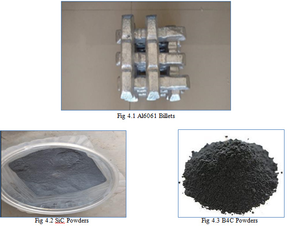
Fig 4.1 shows the Al6061 in the form of the billets that are used in the present study, Fig 4.2, 4.3 sows the reinforcement particles (SiC and B4C) of average particle size 30microns that is used in present study. Table 4.1 - 4.3 shows the properties of base and reinforcement materials.
1) Properties of Aluminium 6061
Table 4.2: Physical properties of Al 6061
|
Properties |
Values |
|
Young’s Modulus (E) GPa |
68.9 |
|
Density (g/cc) |
2.70 |
|
Poisson’s ratio |
0.33 |
|
Tensile strength (MPa) |
120-290 |
|
Melting temperature(°C) |
6500C |
|
Linear thermal expansion coefficient (α) |
2.32*K^-1 |
|
Thermal conductivity(k) W/(m-k) |
151-202 |
2) Properties of SiC Particulates
Table 4.3: Physical properties of Silicon Carbide
|
Properties |
Values |
|
Density (g/cc) |
3.1 |
|
Color |
Black |
|
Elastic modulus(MPa) |
410 |
|
Poisson’s ratio |
0.14 |
|
Compressive strength(MPa) |
3900 |
|
Maximum use temperature (°C) |
1650 |
|
Linear thermal expansion coefficient(α) |
4 |
|
Thermal conductivity(k) W/(m-k) |
120 |
3) Properties of B4C Particulates
Table 4.4: Physical properties of Boron Carbide
|
Properties |
Values |
|
Density (g/cc) |
2.52 |
|
Color |
Black |
|
Elastic modulus(MPa) |
450 |
|
Poisson’s ratio |
0.21 |
|
Compressive strength(MPa) |
4300 |
|
Maximum use temperature (°C) |
2763 |
|
Linear thermal expansion coefficient(α) |
3 |
|
Thermal conductivity(k) W/(m-k) |
90 |
Stir Casting Process: Figure 4.4 shows the casting furnace, processing method and the cast component used for processing of the composite material. The SiC and the B4C particles are pre heated upto 4000C for 4 hours to avoid the thermal mismatch during the casting process, the preheating also helps in removing the moisture content from the materials. The stirring process is carried out where in stirrer is rotated at 300rpm to obtain a good vortex which aids in uniform distribution. The stirring is carried out for a duration of 15-20 min. The stirrer blades made of stainless steel and were coated with ceramic material to minimize the iron pickup by the molten metal. The amounts of SiC and B4C is varied separately from 2 to 8 wt. % in steps of 2 wt. %. The molten melt was kept in static condition and poured in the metal mould to get desired shape for different castings as shown in figure.
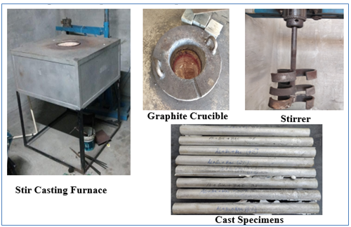
Fig 4.4 Stir Casting Process
B. Specimens preparation
Casted rods were machined and prepared specimens for tensile test, hardness test and wear test as per ASTM standards. The tensile test specimens were prepared as per ASTM E8 standard, brinell hardness test specimens were prepared and tested as per ASTM E10 standard. The photograph of samples prepared for the above tests are shown in below Fig. 4.5.
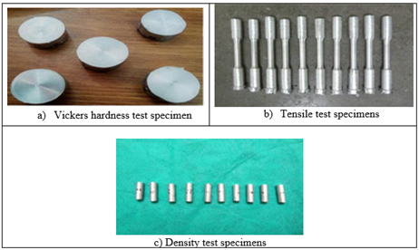
Fig. 4.5 Test Samples
C. Micro Hardness Test – Vickers Hardness Test
The hardness is the ability of the materials to resist indentation. Hardness of both reinforced and non-reinforced composites were measured using Shore-D, Barcol and Vicker’s micro hardness tests. All the tests measure the resistance to the indentation on the composites by the application of load. Fig 4.6 indicates the test apparatus used in the present study. A load of 10 kgf is applied gradually during the test on the surface of the sample. Fig. 4.7 shows indentation calculations and specifications of Victor micro-hardness tester are tabulated in Table 4.5.

Fig. 4.6 Vickers Micro-Hardness testers (VMT)
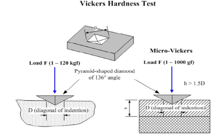
Fig. 4.7 Indentation calculations of Micro-Hardness
Table: 4.5: Specifications of Vickers Micro-Hardness testers (VMT)
|
Model of Hardness Tester |
Everyday Enterprises, Singapore |
|
Loading period |
5 to 45 sec in interval of 5 sec |
|
Loading Weight |
20, 40, 70, 100, 150, 170, 200, 300, 500, 700, 900, 1000 grams |
|
Indenter type |
Victors (Diamond) |
|
Magnification |
100 times |
|
No of indention |
6 |
|
Microscope |
400 times |
D. Tensile Test
The tensile test specimens are prepared as per the ASTM E8 standard as shown in the figure 4.8.

Fig 4.8. Tensile specimen ASTM E8 standard, all dimensions are in mm.
For cast alloys without reinforcement and cast composites, tensile testing are conducted at room temperature. Each cast composite was used to create the specimens. Fig. 4.8 schematically depicts the size and shape of the tensile specimens that adhere to the ASTM E8 specification. The tensile property of the material was determined by testing at least three specimens of 6.35 mm gauge diameter and 26 mm gauge length, machined out of segments of each cast composite and unreinforced alloy, under uniaxial tension in a Hounsfield, Monsanto, H25KS/05, Surrey, England, tensile testing machine at a strain rate of 6.67 x 10⁻⁴ s-1.
E. Density Test
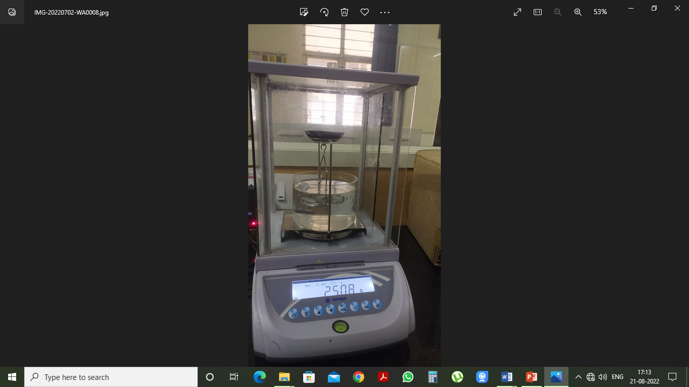
Fig 4.9. Density test apparatus.
The density of jute reinforced composites is calculated by Archimede's principle, according to ASTM D792. The composite samples weighing 1 gram have measured with precise analytical balance and water filled with a beaker. The composite samples are the measure and noted in the air, and then the sample's immersion in the water is the measure and noted, which is equals the weight due to the buoyancy force of volumes. Fig 4.9 shows the density test apparatus used in the present study.
The experimental density is calculated by using the formula shown in equation 4.1 and 4.2.
ρ= WaWa-Wb× Water density……………. (4.1)
Where Wa - the weight of the specimen in air, Wb - the weight of the specimen in water. The theoretical density of a fibre-reinforced composite can be determined by utilizing the accompanying relation:
ρct = 1(Wf?ρf )+(Wm?ρm )
  ……………. (4.2)
where,
Wf = Weight fraction of fibre/reinforcement
Wm = Weight fraction of matrix
ρct = The density of the composite
ρf = The density of the fibre/reinforcement
ρm = The density of the matrix
V. RESULTS AND DISCUSSIONS
Results obtained in the present investigation is been discussed in detail in this section
A. Microstructural Properties
1) Scanning Electron Microscopy (SEM) of SiC
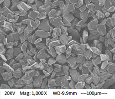
Fig 5.1 SEM of SiC Powders
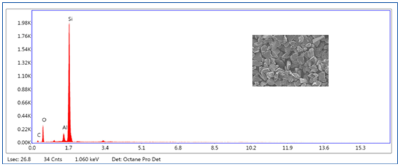
Fig 5.2 EDAX of SiC Powders
Table 5.1: Elemental analysis of SiC powders
|
Element |
Weight percentage |
|
Si |
68% |
|
C |
22% |
|
Al |
3% |
|
O |
7% |
For the micro structural studies, specimens were cut from cast bars and ground with grit paper of various size. The mounted samples were then mechanically polished with a 1μm alumina-powder and fine polishing to near mirror like finish was achieved using 0.5μm diamond paste and etched with Keller’s reagent.Fig 5.1 shows the SEM image of the SiC particles, it can be observed from the images that the reinforcement particles are having sharp corners which helps in adhering to the matrix material. It can be seen that the particles are of uniform size and shape having average particle size of 30microns.
Fig 5.2 shows the EDAX image of the SiC powders and it can be observed that the purity of the material is being highlighted with the sharp narrow peaks in the analysis. Table 5.1 indicates the elemental composition of the SiC where in Si content is found to be the major element.
2) Scanning Electron Microscopy (SEM) of B4C
Fig 5.3 shows the SEM image of the B4C particles, it can be observed from the images that the reinforcement particles are also having sharp corners which helps in adhering to the matrix material. It can be seen that the particles are of uniform size and shape having average particle size of 30microns. Fig 5.4 shows the EDAX image of the B4C powders and it can be observed that the purity of the material is being highlighted with the sharp narrow peaks in the analysis. Table 5.2 indicates the elemental composition of the B4C where in Boron content is found to be the major element.
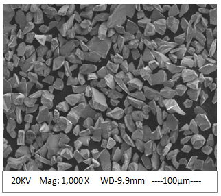
Fig 5.3 SEM of B4C Powders
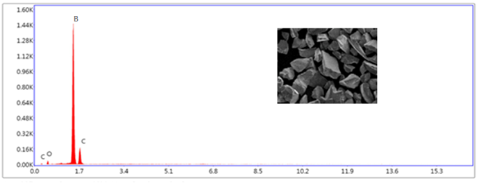
Fig 5.4 EDAX of B4C Powders
Table 5.2: Elemental analysis of B4C powders
|
Element |
Weight percentage |
|
B |
62% |
|
C |
26% |
|
O |
12% |
3) SEM of Composite with SiC and B4C
Fig 5.5 shows the SEM image of the Composite material with SiC and B4C particles, it can be observed from the images that the reinforcement particles are embedded on to the matrix material with good bond. It can be seen that the particles are uniformly distributed in the matrix material which helps in obtaining good mechanical and tribological properties. Fig 5.6 shows the EDAX image of the Composite material with SiC and B4C particles and it can be observed both the identical elements are present in the matrix material and the same is reflected in the Table 5.3.
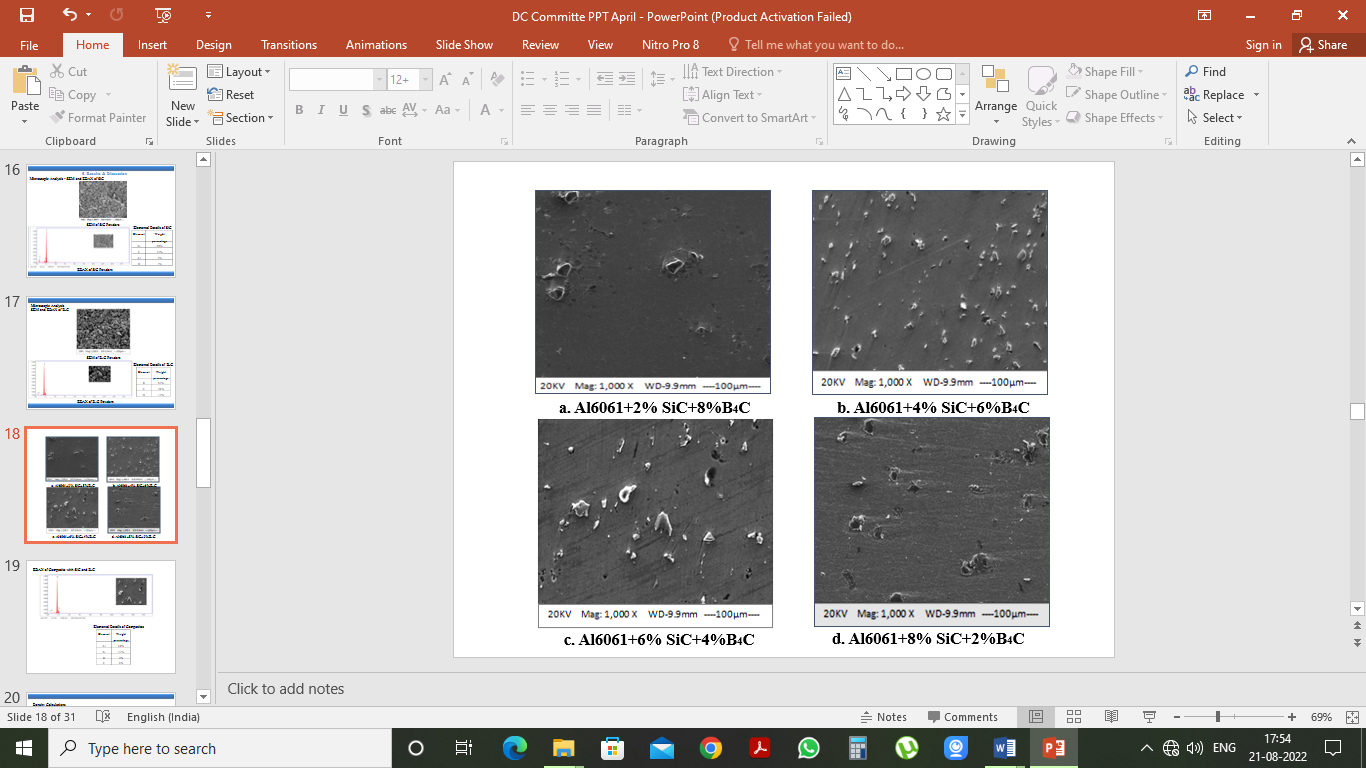
Fig 5.5 SEM of Composite materials
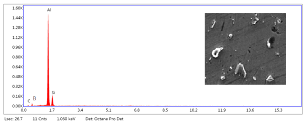
Fig 5.6 EDAX of Composite materials (Al6061+6% SiC+4%B4C)
Table 5.3: Elemental analysis of Composite materials (Al6061+6% SiC+4%B4C)
|
Element |
Weight percentage |
|
Al |
64% |
|
Si |
21% |
|
B |
9% |
|
C |
6% |
B. Evaluation of Mechanical Properties
1) Density Calculations
Theoretical and actual densities of cast composite materials are determined by the Rule of mixture method and Archimedes principle. Based on the values of theoretical and actual densities, porosity percentage in the material is calculated using equation. Actual density of cast composite material will be lesser when compared to the theoretical density of the material and the presence of pores in the cast material leads to reduction in the density of the processed material. Table 5.4 shows the conversion of weight percentage to volume percentage of the matrix and the reinforcement material which has to be used for the density calculations. Table 5.5 indicates the theoretical and actual density of the composite materials.
Table 5.4 Converting weight percentage to volume percentage
|
Sample |
Material |
Percentage by weight |
Percentage by volume |
|
1 |
Al6061 |
100 |
100 |
|
2 |
Al6061 |
90 |
89.78 |
|
SiC |
2 |
1.67 |
|
|
B4C |
8 |
8.55 |
|
|
3 |
Al6061 |
90 |
90.18 |
|
SiC |
4 |
3.37 |
|
|
B4C |
6 |
6.45 |
|
|
4 |
Al6061 |
90 |
90.60 |
|
SiC |
6 |
5.08 |
|
|
B4C |
4 |
4.32 |
|
|
5 |
Al6061 |
90 |
91.02 |
|
SiC |
8 |
6.81 |
|
|
B4C |
2 |
2.17 |
Densities of the material selected: Al6061 - 2.70g/cm3, SiC -3.21 g/cm3, B4C - 2.52 g/cm3
Conversion of weight percentage to volume percentage
For Sample 2= (90/2.7) + (2/3.21) + (8/2.52) = 33.33+0.623+3.174 = 37.12
Volume of Matrix = ((33.33(100/100))/37.12 = 89.78%
Volume of SiC Reinforcement. = ((0.623(100/100))/37.12 = 1.67%
Volume of B4C Reinforcement. = ((3.174(100/100))/37.12 = 8.55%
Similarly, for the other percentage the volume fraction is calculated.
Theoretical Density
For Sample 2 - Composite with SiC and B4C, by rule of mixture method
ρth=Vm ×ρm + Vr ×ρr + Vr ×ρr 
ρth=0.8978*2.7+ 0.0167*3.21+ 0.0855*2.52
ρth=2.69g/cm3
Table 5.5 Theoretical and Actual Density
|
Sample |
Theoretical Density |
Actual Density |
Porosity |
|
1 |
2.70 |
2.65 |
1.85 |
|
2 |
2.69 |
2.58 |
4.08 |
|
3 |
2.70 |
2.61 |
3.33 |
|
4 |
2.71 |
2.64 |
2.58 |
|
5 |
2.73 |
2.66 |
2.56 |
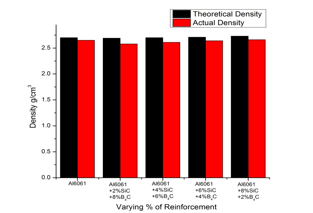
Fig 5.7 Theoretical v/s Actual density
The density of the materials is measured for the sample by weighing it in the air medium and water medium. The weights obtained in the two medium are substituted to the formula i.e weight in the air medium subtracted by weight in the water medium and multiply by the weight in the air medium. The difference between the actual and theoretical density gives the value of porosity. It can be noted from the table that the porosity percentage is found to be minimum in the composite materials. The porosity percentage is found to be higher at the initial percentage of the reinforcement i.e for 2% SiC and 8% B4C composite material and further it has been reduced due to the standard operating procedures adopted for the processing of the materials. Fig 5.7 show the density of the processed materials, where in it can be noted that there is only a marginal difference in the values of the density and the corresponding porosity in being indicated in the Fig 5.8.
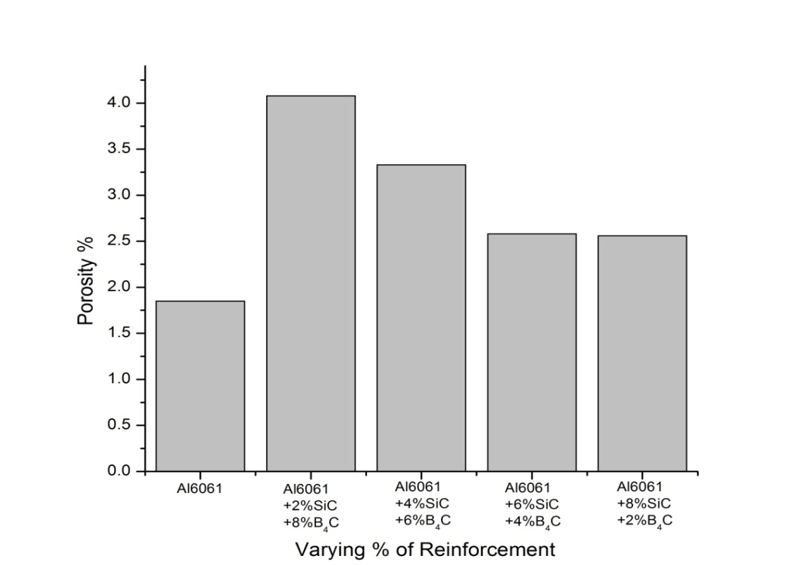
Fig 5.8 Porosity percentage v/s Varying % of Reinforcement
2) Vicker’s Hardness Test (BHN) – Micro Hardness Test

Fig 5.9 Micro Hardness Test Apparatus
For composites made from Al 6061 with SiC and B4C reinforcements at weight percentages of 2, 4, 6, and 8% by weight fraction, hardness has been assessed. When test samples are unsuitable for macro-hardness, micro-hardness testing (Fig. 5.9) is a way of assessing a material's hardness or resistance to deformation. A material's distinct phases, very small/thin samples, complicated forms, and surface coatings/platings can all be tested for hardness using micro hardness methods. Aside from case-hardened layer levels, decarburization or carburization, grind burns, and surface contamination can all be detected with the micro hardness test.
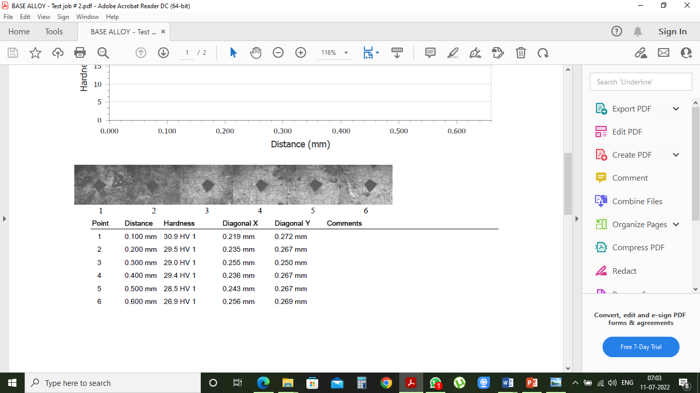
Fig 5.10 Micro Hardness Test Measurement
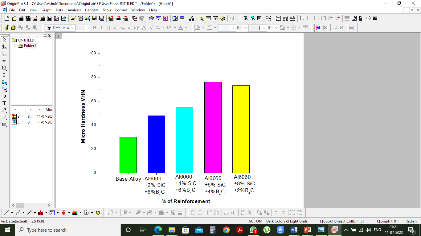
Fig 5.11 VHN V/s Percentage of Reinforcement
Table 5.6: BHN values for varying percentage of reinforcement
|
Sample. No |
VHN |
|
1 |
30 |
|
2 |
47.9 |
|
3 |
54.5 |
|
4 |
75.97 |
|
5 |
73.05 |
With a maximum test weight of 50 kilogrammes, the Vickers hardness test can be carried out on both the micro and macro scales. These tests use a square-based diamond pyramid indenter instead of the regulated pressure and standard duration used in Knoopmicrohardness testing. Using a microscope, the diagonal of the resulting indention is measured, and the test load and this measurement are then input into a precise formula to determine the Vickers hardness value (Fig 5.10).
From Fig. 5.11, it is clear that the Hardness rises as the proportion of reinforcements does. The inclusion of more hard reinforcing particles accounts for the increase in hardness. Sample 4 (6%Sic+4%B4C) among the treated material has a higher hardness than the other samples.
The addition of reinforcing particles increases the composites' resistance to plastic deformation and raises their hardness. According to reports, adding hard ceramic to a soft ductile matrix decreases the ductility of the composites by dramatically raising the hardness value and reducing the amount of ductile metal present. The values of VHN obtained for the corresponding proportion of SiC and B4C reinforcements are shown in Table 5.6.The brittleness of the results obtained for the larger percentage could be the cause of the VHN being increased up to 6% and lowered for 8%, as can also be seen from the figure. More reinforcement particles will be present in the matrix material as the percentage of reinforcement increases, which prevents the reinforcement particles from moving when a load is applied to it. This behavior causes the composite material to become brittle, which lowers the material's hardness.
3) Tensile Strength Test
Similar to the BHN test. Tensile strength test has also been carried out for the processed composite material as per the ASTM E8 standard and an average of three trials for identical percentages has been performed to obtain the tensile strength.
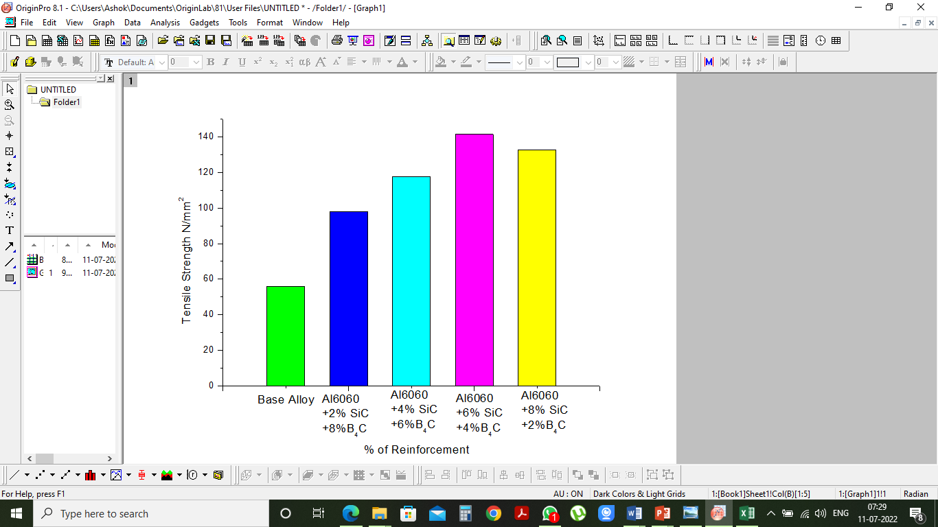
Fig 5.12 Tensile Strength V/s Percentage of Reinforcement
Table 5.7: Tensile Strength values for varying percentage of reinforcement
|
Sample. No |
VHN |
|
1 |
55.8 |
|
2 |
98.1 |
|
3 |
117.7 |
|
4 |
141.4 |
|
5 |
132.8 |
It can be observed from the Figure 5.12. That as the percentage of reinforcement is being increased, there is an increase in the strength of the composite materials. The values of tensile strength obtained for the corresponding SiC and B4C percentage is shown in the Table 5.7. It can be noted from the figure that the 6%SiC and 4%B4C reinforced composite materials have obtained a higher amount of strength compared with the other percentages. The increase in the strength is due to increased hardness of the material and better bonding of matrix and reinforcement materials.
The uniform distribution of reinforcement particles in the matrix material has led to an increase in the strength of the material, But at the higher percentage of reinforcement there is a marginal decrease in the strength due to the brittleness of the materials. The Tensile strength is directly proportional to the hardness of the material and any changes in the hardness leads to changes in the strength of the material.
Conclusion
Following is the summary of the current research work. Conclusions of the experimental, numerical simulation and optimization phases of the research work are being presented. It is observed that results that were taken to be validated against the published work were found satisfactory. The experimental results and the simulations were in good agreement and the following conclusions are drawn from the preliminary investigations: 1) Stir casting process is effectively utilized in processing the composite material with varying percentage of SiC and B4C as reinforcements. 2) Microstructural studies SEM have indicated the presence of the reinforcement material with the matrix with good bonding and uniform distribution. 3) SEM analysis of the composite with 8% SiC and 2% B4C showed more amount of agglomerates at the localized points. This is also proved with reduction in the mechanical properties. 4) SEM of SiC composites upto 6%SiC and 4% B4C volume reinforcement has proven to be good with fair distribution which can be evident from the mechanical properties also. 5) It is noticed that improvement of both hardness and tensile strength was achieved up to 6 wt. % of SiC and degraded for higher percentages. 6) From 0 to 6 weight percent SiC, the alloy\'s hardness doubled to match that of the basic alloy. Hard SiC particles that give the matrix alloy strength and boost its resistance to indentation and scratching are responsible for the increase in hardness.
References
[1] Babalola, P. O., Bolu, C. A., Inegbenebor, A. O. &Odunfa, K. M “Development of Aluminium Matrix Composites: A review”. Journal of Composite Materials, Volume 2, PP 1–11, 2019. [2] DOI: 10.3390/cryst12101357 [3] Kumar, G. B. V., Rao, C. S. P., Selvaraj, N. &Bhagyashekar, M. S. “Studies on Al6061-SiC and Al7075-SiC Metal Matrix Composites”, Journal of Minerals and Materials Characterization and Engineering, Volume 4, PP 43–55, 2020. DOI: 10.4236/jmmce.2010.91004 [4] Kale, V. C. “Aluminium Based Metal Matrix Composites for Aerospace Application: A Literature Review” Journal of Mechanical and Civil Engineering, Volume 12, 2278–1684, 2019. [5] DOI: 10.9790/1684-12653136 [6] P.B.Pawar, Wable “A Comprehensive Study of Aluminum Based Metal Matrix Composites: Challenges and Opportunities”Materials Today: Proceedings Volume 5, Issue 11, Part 3, 2018, Pages 23937-23944, 10.1016/j.matpr.2018.10.186 [7] Arunkumar K N ,Dr. G B Krishnappa, “Mechanical Properties of Aluminum Metal Matrix Composites – A Review”, International Journal Of Engineering Research & Technology (IJERT)Volume 11, Issue 03 (March 2022). DOI: 10.17577/IJERTV11IS030111 [8] S.T. Mavhungu, E.T. Akinlabi, M.A. Onitiri, F.M. Varachia\"Aluminum Matrix Composites for Industrial Use: Advances and Trends\" Procedia Manufacturing Volume 7, 2017, Pages 178-182. [9] DOI: 10.1016/j.promfg.2016.12.045 [10] Karthik B M,Gowrishankar M C,SathyashankaraSharma,PavanHiremath,ManjunathShettar&Nagaraj Shetty “Coated And Uncoated Reinforcements Metal Matrix Composites Characteristics And Applications – A Critical Review”, Volume 4, 282-291, 2020, DOI: 10.1080/23311916.2020.1856758 [11] H.Ye\"An overview of the development of Al-Si-Alloy based material for engine applications” Journal of Materials Engineering and Performance, Volume 12, PP 288-297, 2018. [12] DOI: 10.1361/105994903770343132 [13] Mohammed Imran, A.R. Anwar Khan “Characterization of Al-7075 metal matrix composites: a review” Characterization of Al-7075 metal matrix composites: a review” Composites Science and Technology Volume 67, PP 3369–3377, 2018, DOI: 10.1016/j.jmrt.2017.10.012 [14] Mohamed F. Ibrahim, Hany R. Ammar, Agnes M. Samuel, Mahmoud S. Soliman, Victor Songmene and Fawzy H. Samuel “Why Al-B4C Metal Matrix Composites? A Review” Advances in High Entropy Alloys., 2021 DOI: 10.5772/intechopen.95772
Copyright
Copyright © 2024 Kashinath S V H, YogavardhanSwamy G N, Venkatesh . . This is an open access article distributed under the Creative Commons Attribution License, which permits unrestricted use, distribution, and reproduction in any medium, provided the original work is properly cited.

Download Paper
Paper Id : IJRASET66020
Publish Date : 2024-12-19
ISSN : 2321-9653
Publisher Name : IJRASET
DOI Link : Click Here
 Submit Paper Online

