Ijraset Journal For Research in Applied Science and Engineering Technology
- Home / Ijraset
- On This Page
- Abstract
- Introduction
- Conclusion
- References
- Copyright
Analysis and Design of Electrical Transmission Towers with Various Sections and Bracing Configurations
Authors: Md Ilyas, Prof. Rajkumar Tadkal
DOI Link: https://doi.org/10.22214/ijraset.2024.64254
Certificate: View Certificate
Abstract
This study focuses on the analysis and design of a 400kV electrical transmission tower with a height of 50 meters. The tower was modeled in STAAD.PRO using three distinct steel sections Angle, Tube, and Channel combined with various bracing configurations, including X, K, and D-bracings. The main objective of this study is to determine the most efficient and economical configuration for the design of Transmission tower. The tower is analyzed for Dead load, Live load and wind load as per the codes. The study concludes that transmission towers with angled sections and X-bracing exhibit moderate displacement, minimal reaction forces, and reduced structural weight, making them a preferred design choice. Manual calculations were performed to design the connections and footing, ensuring structural integrity. The results confirm that the tower\'s connection design is safe and reliable.
Introduction
I. INTRODUCTION
Transmission towers, commonly referred to as power towers or electricity pylons, are critical structures that support overhead power lines. They enable the transmission of high-voltage electrical energy from power plants to substations across long distances, ultimately supplying electricity to homes and businesses. Typically constructed from steel, these towers are designed to withstand a variety of environmental challenges, including strong winds, ice loads, and the weight of the cables they carry. They come in different configurations such as lattice, tubular, and monopole designs, each suited to specific voltage levels and terrain types. Key components of a transmission tower include the main structural body, insulators to prevent electrical leakage, cross arms for mounting conductors, and grounding systems for safety. Strategic placement of these towers ensures the integrity and efficiency of the power grid while minimizing environmental impact. Regular maintenance, including inspections and protective coatings, is crucial to maintaining their structural health and ensuring a reliable electricity supply. In summary, transmission towers are fundamental to the electrical infrastructure, facilitating the dependable and efficient distribution of electricity that supports modern society and economic growth.
II. LITERATURE REVIEW
Sai Avinash P [3] (Analysis and Design of Transmission Tower using STAAD.PRO). This thesis investigates the design of a 49-meter-tall transmission tower, using STAAD.PRO to support a 220 kV double circuit cable. To ensure a safe and cost-effective design, both structural and electrical considerations are addressed. In compliance with IS 800-2007 standards, wind forces are identified as having a significant impact on the tower's self-weight, as well as on the conductors, insulators, and the tower structure itself. The study focuses on optimizing the tower by incorporating X and K bracings and using different steel sections, all analyzed through static analysis. The findings reveal that modifying the bracings and steel sections leads to a notable 6% reduction in the tower's weight, achieved through improvements based on displacement values. This optimization contributes to a more efficient and economical design for transmission towers.
Jyoti Besra [5] (Analysis and Design of Transmission Tower using STAAD.PRO V8I) This study presents a structural analysis and design of a 40-meter transmission tower with X-bracing, utilizing STAAD Pro V8i. The tower is modeled using Indian angle sections based on the properties of its elements. Various load combinations were analyzed, with wind forces being the most critical. The analysis also assessed maximum displacements at different nodes and under varying load conditions to evaluate the tower's response.
These displacement values assist engineers in determining if the structure can safely withstand the applied loads without undergoing excessive deformation or risk of failure. By ensuring the displacements remain within acceptable limits, the design ensures the tower's structural integrity under operational conditions, providing both safety and reliability for its intended purpose.
Sniawlangki T Chyrmang [7] (Analysis of Transmission Tower) This paper examines 400 kV double circuit transmission line towers, or suspension towers, using STAAD.PRO V8i SS5. The analysis incorporates forces such as wind load per IS 802 (Part I/Sec 1):1995, dead load, and earthquake load per IS 1893 (Part 1):2015. The towers, with a height of 50 meters and a base width of 10 meters, are located in seismic zones and divided into wind zones 2 and 6. Angle sections are used, with X and K bracing systems considered. The study concludes that towers with X bracing offer a 3.07% reduction in steel weight compared to those with K bracing, making X bracing more cost-effective. Despite the higher base shear in wind zones, both bracing systems show minimal differences in deflection under various loads.
Dr. S. A. Halkude [11] (Analysis and Design of Transmission Line Tower 220KV: A Parametric Study) This study explores optimizing the geometric configuration of a self-supporting 220 kV transmission line tower by analyzing various parameters such as the width-to-height ratio, bracing systems (X, K, XBX), and the number of panels in the tower body. The tower, designed at a constant height of 20 meters, considers consistent load parameters, including wind forces per IS: 802 (1995), and adheres to uniform clearances, spans, conductor, and ground wire specifications. The research focuses on evaluating slenderness effects, critical sections, forces, deflections, and overall tower weight. A comparative analysis reveals that X bracing offers space efficiency, reducing base width by up to 55% compared to XBX and K systems, making it ideal for land-constrained areas. However, X bracing becomes less economical when the width-to-height ratio exceeds 0.139, leading to increased tower weight by 3% to 13%. The study emphasizes the impact of axial forces and displacements on the structural performance and stability of various bracing systems.
A.Jesumi [13] (Optimal Bracing System for Steel Towers) This study evaluates various bracing configurations—X-B, single diagonal, X-X, K, and Y bracings—for their cost-effectiveness in steel lattice towers with heights of 40 meters (13 panels) and 50 meters (16 panels).Only 28–30% of the towers are straight, and the remaining 70–72% are tapered. Wind loads in vertical, normal, and parallel directions were examined using IS: 875-1987 Part 3 as a basis. Maximum loads occurred under diagonal wind conditions. Taking into account the wind both normal and diagonal to the tower face, the towers were evaluated under two load combinations: dead load (DL) and wind load (WL). A comparison of various bracing styles and their associated weights and joint displacement showed that, up to a height of fifty meters, Y bracing is the most economical option.
III. OBJECTIVES
- To Conduct a comprehensive assessment of the structural performance of transmission towers.
- Investigate and compare different configurations of bracings (X, K and D bracing) to identify optimal design that minimize material usage while ensuring structural integrity.
- Analyse the cost implications associated with different tower sections and bracing configurations.
- Design of Connections using relevant data from analysis.
IV. METHODOLOGY
To design a 50m transmission tower, first determine key parameters including capacity of the tower, terrain, and climatic conditions using IS 875 Part 3 for wind pressure and IS 802 for load specifications. Ensure minimum ground clearance as per IS 5613 and consider ACSR conductor specifications from IS 398. Model the tower using STAAD.PRO with various steel sections (Angle, Tube, Channel) and bracing types (X, K, D) to create nine different models. Define the geometry, assign material property and section properties, apply loads, and set support conditions. Analyze the structure for forces and moments, then design members and connections as per IS 800:2007, optimizing sections and preparing detailed reports.
A. Transmission Tower Geometry
Table 1: Transmission tower dimensions
|
Specific Height |
Linear distance(m) |
|
Total Height (H) |
50.0m |
|
Base Width (Square) |
8.5m |
|
Ground Clearance distance |
28.02m |
|
Distance between conductors measured perpendicularly |
6.0m |
|
Conductor and ground wire's perpendicular distance from one another |
9.0m |
|
Conductor Span |
400.0m |
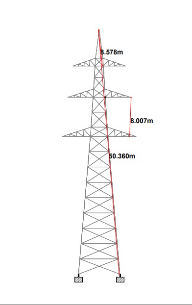
Figure 1: Transmission tower geometry
B. Design Parameters
Each tower member's design and fulfilment of a code check is evaluated in the STAAD software based on the allowed stress design approach, as per IS:802(Part-1/ Sec-1): 1995.
|
Type of tower |
Suspension Tower |
|
Transmission line voltage |
400KV |
|
Angle of line deviation |
0o-2o |
|
Terrain-Type |
1 |
|
Type of Circuits |
Double Circuits |
|
Conductor material “ACSR” |
54/7/3.53 mm |
|
Overall diameter of Conductor |
31.77 mm |
|
Overall diameter of Ground Wire |
10.98 mm |
|
Co-efficient of Linear Expansion(α) in per degree Celsius “ACSR” |
19.3X10⁻⁶/oC |
|
Elastic modulus(E) in Kg/mm2 “ACSR” |
7034Kg/mm2 |
|
Elastic modulus(E) in Kg/mm2 “GSS” |
19361Kg/mm2 |
|
Maximal Temperature of conductor |
75oC |
|
Maximal Temperature of Ground wire |
53oC |
|
Everyday Temperature |
32oC |
|
Minimum Temperature |
-18oC |
|
Design Period |
100 Years |
|
Type of Peak |
Trigonal |
|
Type of Insulator |
String |
Table 2: Design Parameters
C. Elevational view of transmission tower
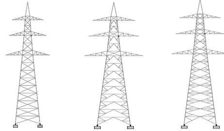
Figure 2: Transmission towers with X, K and D-bracing
D. Design of footing
- Compressive Load = 149.03KN
- Pult = 296.92KN
- Design of Pedestal (Chimney)
- Providing 8 No’s of 16mm dia bar.
- Provide 10mm dia bar reinforcement @250mmC/C.
4. Design of Pad footing
- Dimension of footing = 2.5*2.5m
5. Area of steel reinforcement of footing
- Providing 16mm dia bars at 250mm C/C.
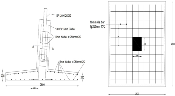
Figure. 3: Reinforcement details of Footing and Pedestal
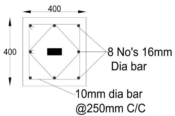
Figure.4: Section at A-A reinforcement details of Pedestal
E. Design of connections
1) Bracing Members (ISA110X110X8)
- Member force = 7.13KN
- Shear Capacity of Bolt
Using 4.6 grade bolt of 10mm
Vdsb = 22.46KN
- Bearing capacity of Bolts
Vdpb = 27.55KN
- No. of Bolts = 0.38 ≅ 2 Bolts
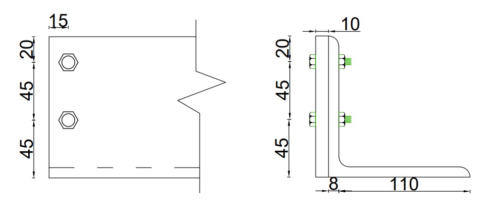 Figure.5: Bolted Connection design of Bracings
2) Horizontal Members (ISA90X90X8)
- Max Force = 10.89KN
- Shear Capacity of Bolt
Using 4.6 grade bolt of 10mm
Vdsb = 22.46KN
- Bearing capacity of Bolts
Vdpb = 27.55KN
- No. of Bolts = 0.59 ≅ 2 Bolts
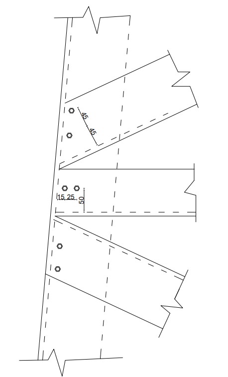
Figure.6: Bolted Connection design of Bracings to Column and Horizontal member to Column
3) Vertical Members (ISA120X120X10)
- Max Force = 142.69KN
- Design strength of bolt in Slip Resistance
Vdsf = 37.93KN
Let us provide HSFG Bolt of 12mm dia
- No. of Bolts = 6 Bolts
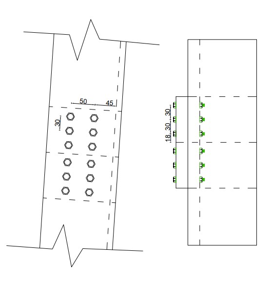
Figure.7: Connection design for Column to Column
V. RESULTS & DISCUSSIONS
A. Height V/s Displacements for X-Bracing in mm
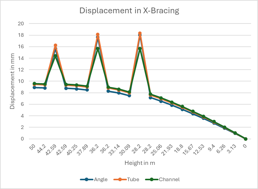
Figure 8: Height V/s Displacement in X-Bracing
B. Height V/s Displacements for K-Bracing
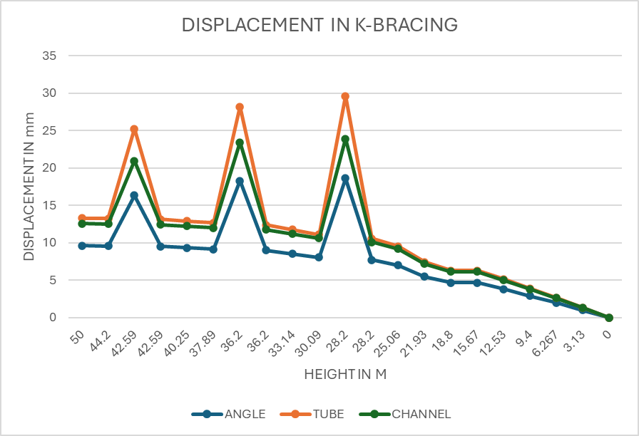
Figure.9: Height V/s Displacement in K-Bracing
C. Height V/s Displacements in D-Bracing
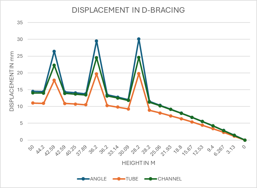
Figure.10: Height V/s Displacement in D-Bracing
The Peak displacement here is noted at cross arms due to load of Conductors and Insulators.
D. Comparative results of models with X-bracing
|
PARAMETERS |
ANGLE SECTION WITH X-BRACING |
TUBE SECTION WITH X-BRACING |
CHANNEL SECTION WITH X-BRACING |
|
Node Displacement (Maximum Displacement) |
18.05mm |
18.35mm |
15.96mm |
|
Reaction (Maximum Resultant) |
149.03KN |
161.62KN |
187.32KN |
|
Member Forces (Maximum Axial Forces) |
142.69KN |
153.92KN |
177.37KN |
|
Total Weight of Tower |
249.41KN |
281.59KN |
350.09KN |
Table 3: Comparative Results for X-Bracing
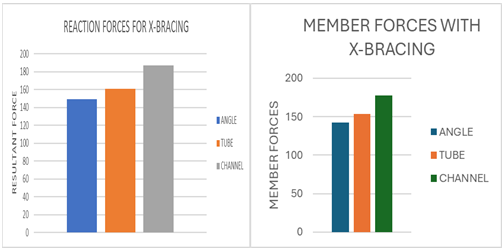
Figure.11: Reaction forces and Maximum member forces for X-Bracing
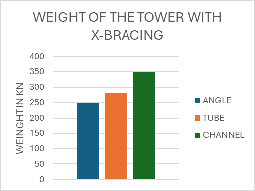
Figure.12: Weight of the tower for X-Bracing
E. Comparative results of models with K-bracing
|
PARAMETERS |
ANGLE SECTION WITH K-BRACING |
TUBE SECTION WITH K-BRACING |
CHANNEL SECTION WITH K-BRACING |
|
Node Displacement (Maximum Displacement) |
18.64mm |
29.62mm |
23.911mm |
|
Reaction (Maximum Resultant) |
157.69KN |
211.93KN |
238.89KN |
|
Member Forces (Maximum Axial Forces) |
154.01KN |
205.73KN |
227.36KN |
|
Total Weight of Tower |
272.43KN |
297.23KN |
369.14KN |
Table 4: Comparative Results for K-Bracing
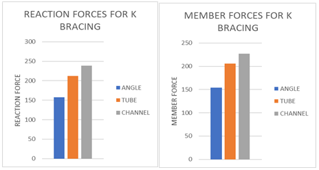
Figure.13: Reaction forces and Maximum member forces for K-Bracing
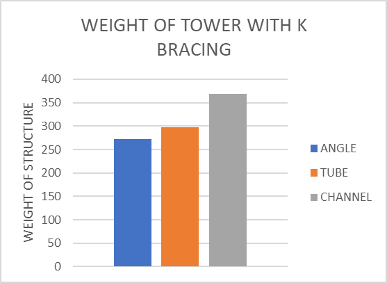
Figure.14: Weight of the tower for K-Bracing
F. Comparative results of models with d-bracing
|
PARAMETERS |
ANGLE SECTION WITH D-BRACING |
TUBE SECTION WITH D-BRACING |
CHANNEL SECTION WITH D-BRACING |
|
Node Displacement (Maximum Displacement) |
30.15mm |
19.81mm |
24.64mm |
|
Reaction (Maximum Resultant) |
222.48KN |
182.95KN |
258.4KN |
|
Member Forces (Maximum Axial Forces) |
217.39KN |
176KN |
246.25KN
|
|
Total Weight of Tower |
325.36KN |
339.95KN |
421.15KN |
Table 5: Comparative Results for D-Bracing
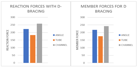
Figure.15: Reaction forces and Maximum member forces for D-Bracing
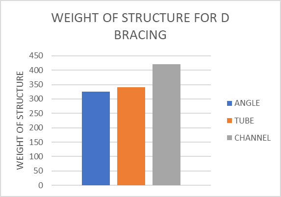
Figure.16: Weight of the tower for D-Bracing
G. Discussions
- Channel sections, being the stiffest, display the least displacement, while tube sections exhibit the highest displacement, indicating lower stiffness. Angle sections offer moderate stiffness, with displacement falling between tube and channel sections.
- Angle sections experience the lowest resultant and member forces, followed by tube sections. Channel sections endure the highest forces, indicating less efficient load distribution compared to the other two section types.
- Angle sections are the lightest among the tower types, with tube sections having moderate weight and channel sections being the heaviest. The above scenario applies for bracing configurations X, K, and D.
Conclusion
1) Angle sections offer moderate stiffness and lowest member forces, making them efficient and lightweight for X-bracing systems. 2) Across a range of bracing configurations, tube sections offer balanced performance with moderate weight, stiffness, and member forces. However, displacement, member and reaction forces are lowest in tube section with D-bracing. 3) Although channel sections are the stiffest, they have the highest weight, member forces, and inefficient load distribution when used with X, K, or D bracing. Due to these higher forces and weight, channel sections are less optimal. 4) The X-bracing arrangement yields the best results in terms of displacement, member forces, reaction forces, and least amount of structural weight out of all the bracing configurations. 5) Angle sections with X-bracing are the most efficient in terms of displacement, reaction forces, member forces, and overall weight, making them the most economical option for structural design. 6) The reaction forces, member forces, and displacement are most significant under the load combination of dead load (DL) +live load (LL).
References
[1] Central Bureau for Irrigation and Power (CBIP) Manual [2] Design of steel structures, 3rd edition, by S.K. Duggal. [3] T. Abhiram Reddy, K. Murali, DSVSMRK. Chekravarty, P. Anil Sagar, Analysis and Economical Design of Transmission Line Towers of Different Configurations Subjected to Wind Load, International Journal of Civil Engineering and Technology (IJCIET), Scopus Indexed, Volume 9, Issue 1, January 2018, pp. 388–397, ISSN Print: 0976-6308 and ISSN Online: 0976-6316 [4] N. Mahesh, V. Ranga Rao, Design & Estimation of Electric Tower, International Journal of Civil Engineering and Technology (IJCIET), Scopus Indexed, Volume 8, Issue 1, January 2017, pp, ISSN Print: 0976-6308 and ISSN Online: 0976 -6316. [5] Sai Avinash, Rajashekhar P, Siddhardha R, Harinarayanan R, Chamandeep and Yashdeep, Analysis and Design of Transmission Tower using STAAD.PRO, International Journal of Earth Sciences, Indexed in Scopus Compendex and Geo-base Elsevier, Geo-Ref Information Services-USA, List B of scientific Journals, Poland, Directory of Research Journal, Volume 09, No. 03, ISSN 0974-5904, [6] B. Rohini, Dr.R. Sushmitha, J. Sravani, Analysis And Design of Transmission Towers Using Staad Pro, 3rd International Mountain and Ecology Congress Within the Framework of Sustainable Development (MEDESU2022). October 20-21, 2022/ Trabzon-Türkiye PROCEEDINGS BOOK [7] Jyoti Besra, Dr. Jitu Kujur, Analysis And Design of Transmission Tower Using Staad. Pro V8i, International Research Journal of Modernization in Engineering Technology and Science, Volume: 05 Issue: 10/ October-2023, e-ISSN: 2582-5208 [8] Anuja Keshav Jadhav, Prof. S. R. Suryawanshi, Dr. N. V. Khadake, Analysis and Design of Transmission Tower Using Staad Pro for Indian Condition, International Journal for Research in Applied Science & Engineering Technology (IJRASET), Volume 10 Issue V May 2022, ISSN: 2321-9653; IC Value: 45.98; SJ Impact Factor: 7.538 [9] Sniawlangki T Chyrmang, Prof. Geetha K, Analysis of Transmission Tower, International Research Journal of Engineering and Technology (IRJET) Volume: 07 Issue: 08 |Aug 2020 p-ISSN: 2395-0072, e-ISSN: 2395-0056 [10] Avinash B. Patil, Nikhil A. Patil, Vishal N. Godase, Avinash R. Somatkar, Afroj B. Pathan, Prof. V. P. Bhusare, Comparative Study on 4-Legged Transmission Line Tower with Different Bracings by using STAAD Pro, Journal of Advances and Scholarly Researches in Allied Education Vol. XV, Issue No. 2, (Special Issue) April-2018, ISSN 2230-7540 [11] Abdulaqder M. Tah, Kamiran M. Alsilevanai, Mustafa Özakça, Comparison of Various Bracing System for Self-Supporting Steel Lattice Structure Towers, American Journal of Civil Engineering 2017; 5(2): 60-68 doi: 10.11648/j.ajce.20170502.11 ISSN: 2330-8729 (Print); ISSN: 2330-8737 (Online) [12] Yasaswini, S. V. N. L. Lalitha and Shefali Talati, Multi Voltage Multi Circuit Transmission Tower, Design to Reduce Right of Way, Indian Journal of Science and Technology, Vol 9(33), DOI: 10.17485/ijst/2016/v9i33/95239, September 2016, ISSN (Print): 0974-6846 ISSN (Online): 0974-5645 [13] Dr. S. A. Halkude, Mr. P. P. Ankad, Analysis and Design of Transmission Line Tower 220 kV: A Parametric Study, International Journal of Engineering Research & Technology (IJERT), Vol. 3 Issue 8, August - 2014 IJERT ISSN: 2278-0181. [14] Vinay R.B, Ranjith, Bharath, Optimization of Transmission Line Towers: P-Delta Analysis, International Journal of Innovative Research in Science, Engineering and Technology , Vol. 3, Issue 7, July 2014, ISSN: 2319-8753 [15] A. Jesumi, M.G. Rajendran, Optimal Bracing System for Steel Towers, International Journal of Engineering Research and Applications (IJERA), Vol. 3, Issue 2, March -April 2013, ISSN: 2248-9622, pp.729-732 [16] M.Selvaraj, S.M.Kulkarni, R.Ramesh Babu, Behavioural Analysis of built-up transmission line tower from FRP pultruded sections, International Journal of Emerging Technology and Advanced Engineering Website: www.ijetae.com (ISSN 2250-2459, Volume 2, Issue 9, september (2012).
Copyright
Copyright © 2024 Md Ilyas, Prof. Rajkumar Tadkal. This is an open access article distributed under the Creative Commons Attribution License, which permits unrestricted use, distribution, and reproduction in any medium, provided the original work is properly cited.

Download Paper
Paper Id : IJRASET64254
Publish Date : 2024-09-16
ISSN : 2321-9653
Publisher Name : IJRASET
DOI Link : Click Here
 Submit Paper Online

