Ijraset Journal For Research in Applied Science and Engineering Technology
- Home / Ijraset
- On This Page
- Abstract
- Introduction
- Conclusion
- References
- Copyright
Design and Analysis of Cube Satellite Structure
Authors: Miss. Bhagyashri Sunil Jadhav, Dr. Digambar Dharmraj Date
DOI Link: https://doi.org/10.22214/ijraset.2023.56353
Certificate: View Certificate
Abstract
Currently, with new technologies, lower and cheaper satellites have been designed and launched. similar satellites fit as educational tools to unborn masterminds. With many kilograms and reduced confines, they\'ve simple operation, despite being complete systems able to perform real operations. During CubeSat platform development, the conception of the design process is formulated and standard physical connections are proposed to find number of optimal design result in terms of introductory limitations and features comity. Specifically, new modular structure is proposed in order to allows flexible subsystems agreement. This paper checks and estimates the eventuality of one- unit CubeSat platform
Introduction
I. INTRODUCTION
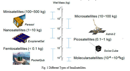
Technological advances in Aerospace Engineering give means to develop a simple, cheap but still complete satellite to apply knowledge and technology. Such a design offers the occasion of joining scholars in the whole lifecycle of the device, known as CubeSat. The CubeSat consists of a 10 cm x 10 cm x 11 cm satellite, weighting at most1.33 kg, being easier and cheaper to design, make and launch than a conventional bone . Small satellites, similar as CubeSats, are gradationally being used to apply operations conservatively permitted to lesser satellite systems. Universities, governments and manufacturers are precipitously turning to CubeSats as ready- to- figure systems suitable to deliver low- cost and rapid-fire door to space aimed at exploration and development along with operative operations similar as earth compliances, deep space and asteroid captures. Different CubeSat factors are commercially available as out- the- shelf standard factors delivered by a defined volume of suppliers. A way to overcome this issue is to ameliorate the capacity to acclimatize eachmicro-satellite. With the relinquishment of advanced manufacturing( 3D- printing) ways similar as cumulative manufacturing, some charge specific capabilities can be painlessly fabricated into a system that marketable off- the- shelf factors may not be suitable to give, in terms of affordable optimized system. The conception of ultramodern SmallSats has numerous possible characteristics. similar characteristics can vary depending on the charge type, the volume of satellites to be stationed, and numerous other aspects related to design, fabrication, testing, and launching a given satellite. CubeSats( from one to six units in size) can be realized at low cost by means of specific accoutrements which can be acquired on- line, and marketable off- the- shelf factors that indeed haven't been spaceflight eligible ahead.
II. ANATOMY OF CUBESAT
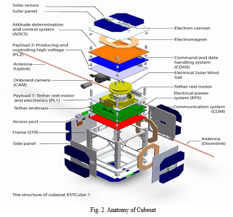
To design a CubeSat structure duly, one must consider the terrain it'll operate, being interfaces and how information flows between the two of them. Functional and Physical limits must be determined as well. The abstract development consists of assaying the conditions that will lead to a new product design, the anticipated performance and the armature to be used in order to negotiate the charge. It's composed by necessary analysis, responsible for studying the feasibility of the CanSat, functional limitations in being systems and technological advances; functional analysis, responsible for defining the objects the new system is to achieve; functional analysis, that will settle the specialized means to assure the system will fulfill the objects; feasibility description, that will determine the possibility of the system to viably attend the requirements.
In terms of knowledge of manufacturing works in the process of CubeSats expansion, design and computation stages, growth of sense and electric plates and enhancement calculation plans, modeling and analyses have to carried out. The design and the modeling processes include the ensuing stages:
- Design and strength examination and computations;
- Mass and instigation of indolence computations,
- Define position centre of mass and the main indolence axes;
- Thermal computations;
- Computations of internal and external disturbing moments CubeSat egging ;
- Gas setting computations for deep sections;
- Estimation of possibility of meteorite effect and corrosion of external shells;
- Estimation of radiation exposure for bias, glass, coatings and structuralnon-metallic rudiments;
- Dynamic analysis aimed to control musts or to check the structure stiffness and action of the exposure system;
- Ballistic design;
- Power force system computations, exposure system and other system designs.
The top focus of this exploration paper is the CubeSat centre of mass movement stabilization system in the side aeroplane applied during the line correction phases. also, a high- thrust sustained propulsion system can be used only if by opposing or linearly moving combustion chamber shall be using in the correction stage to control CubeSat movements. Considering the design process in terms of the product development stages, similar process should cover of the specialized specification related to CubeSat, development of draft offer, abstract and its specialized design. It's egregious that in the process of CubeSat design the introductory parameters of systems, line characteristics, operation program and the structure design should be putting into account
III. ANALYSIS OF THE CUBESAT
A. System Scale
The analysis of a complex system can be performed considering functional blocks of the system divided in physical scale of factors. The loftiest position of the scale is the system, being followed by subsystems, factors, subcomponents and corridor. In case of the structure, the system is the CubeSat, subsystems can be Energy Power Supply, Control and Structure, among others. Structure factors can be classes, frames and rails. A subcomponent of the frames can be the faces, and eventually the faces corridor are plates, screws, screw- nuts and tapes.
B. System Terrain
To design a CubeSat structure duly, one must consider the terrain it'll operate, being interfaces and how information flows between the two of them. Functional and Physical limits must be determined as well. In this paper the CubeSat interacts with the P- cover and after launching with space terrain. The commerce between the CubeSat and the P- cover is critical for this design, handed that rudiments( forces, climate, heat) will be transmitted substantially by structural subsystem
???????C. Conceptual Development
The abstract development consists of assaying the conditions that will lead to a new product design, the anticipated performance and the armature to be used in order to negotiate the charge. It's composed by necessary analysis, responsible for studying the feasibility of the CanSat, functional limitations in being systems and technological advances; functional analysis, responsible for defining the objects the new system is to achieve; functional analysis, that will settle the specialized means to assure the system will fulfill the objects; feasibility description, that will determine the possibility of the system to viably attend the requirements.
IV. STRUCTURAL CONDITIONS FOR AN 1U CUBESATT
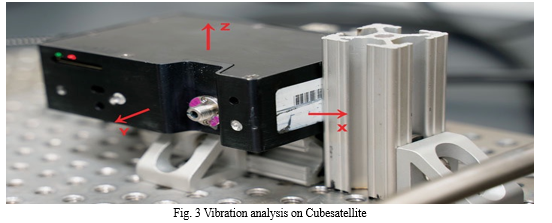
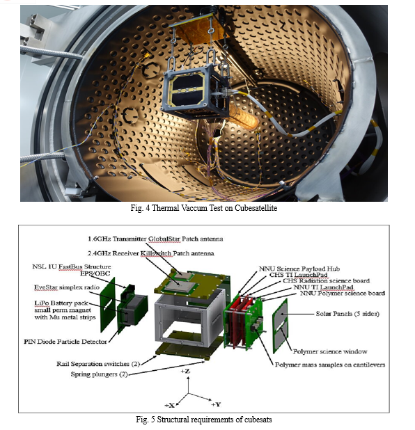
To design a CubeSat there's a set of rules assessed by space agencies, the CubeSat Design Specifications( CDS). Those rules not only specify accoutrements and confines for the CubeSat but also demand it to go through some tests vibration, impact and heating tests. Those tests are divided into Qualification Tests, Protoflight Tests and Acceptance Tests. They aim substantially to assure the trustability of the system. According to the CDS, the emergency situations of the tests depend on the launch, being specified by the charge leader. The developer, still, must use documents LSP- REQ-317.01 and shop- STD- 1540 to misbehave with the conditions. Those norms put arbitrary vibration test, sinusoidal vibration test, impact test and thermal test.
V. CUBESAT STRUCTURE DESIGN AND MODELLING
A. Individual Part Configuration & Design
- Bulkheads
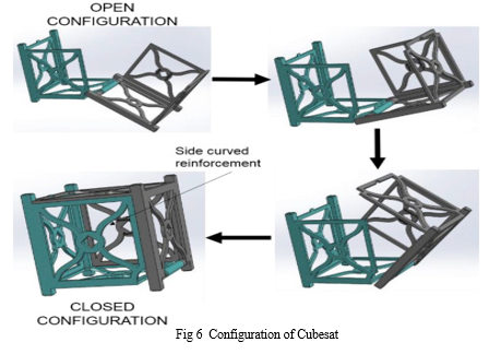
Four bulkhead designs have been created to use throughout the structure. As the name bulkhead suggests, this part is meant to separate the structure into sections where each section is 1U, totaling 6Us in the direct 1x6U configuration. The bulkheads have an inversely important part in adding structural integriety to the CubeSat. It's the minimal requrement for structural support. Bulkhead is used as the introductory structural support to hold the rails in place and produce volume inside the satellite Each mound can allow for an approximate outside of 4 PCBs depending on the clearaence demanded inbetween each board. The distance of these boards can be increased or dropped by changing out the standard M3 standoffs with bones of asked length.
A standoff is a simple aluminum extrusion with either womanish or manly threaded ends. In this case, one end is womanish and the other is manly. Standoffs are also threaded into each other with PCBs squeezed between them. The standoffs that also connect the PCB mound to the classes have two womanish threading ends. The structure has been designed to bear a bulkhead mounted every113.5 mm which is the length of one U. A typical 1U volume isn't actually a perfect cell of 100 mm x 100 mm x 100 mm. Rather, there's a long side making the confines of the U, 100 mm x 100 mm x113.5 mm. The redundant length in the one direction is used for element concurrence inside the structure. Along the rails, holes have been included at the locales separating each U for bulkhead underpinning. Holes have also been included at the half distance mark of113.5 mm in case some tackle requires the neutralize of these bulkheads. If special tackle requires the junking of a bulkhead and the customized design doesn't include a bulkhead at least every113.5 mm, it's important to estimate the structural need created by the absence of that bulkhead. Rerunning structural analysis simulations would also be salutary to insure the satellite’s structural integrity.
2. Rails
The rails the structural piece that will guide the satellite into and out of the deployer. The rails are also designed for mounted to by classes, thermal strips, and solar panels. The long 700 mm piece of aluminum is intended for holding the tight coplanar demand specified by NanoRacks. The surface of the satellite rails must be coplanar within-0.1 mm and the external corners of the rail confines must be 100-0.1 mm from each other. This is a delicate demand for a structure nearly three diggings of a cadence in length. Bulkhead D Bulkhead B Bulkhead C 18 A single long piece of aluminum is used for each rail to minimize the machining conditions.
In the sampling along the y- axis, bulkheads are the only corridor between the rails as shown in figure. This design consideration addresses the 100-0.1 mm demand the smaller the corridor between the limiting confines, the easier it's to make those corridor mound up and equal a asked length within the forbearance. One part between each rail is the minimal number of corridor and thus is optimal for the rail separation demand. It's possible to make the rails and the bulkhead all one piece, but this would introduce machining challenges. Structure erected with only rails and bulkheads Each rail has an disposed pattern of holes used for mounting end caps, bulkheads and solar panels. Space for mounting fresh tackle directly to the rails has been included. Anywhere on the rail is respectable for adding mounting holes except for the black regeon. This space is designated for deployer contact and as a demand shouldn't have any fasteners gaps or holes on it with the exception for rail mounted switches. The rail has been designed with a consistence of 3 mm which is the thickest option availible to prop structurally and allow for threading into while still not impeding on the asked innards volume of the satelliite. It's recommended to start with a 100-0.1 mm 100-0.1 mm 19 piece of aluminium angle stock with consistence of a quarter inch. The redundant material is helpful for maching down to the asked flatness of-0.1 mm.
3. End Caps
End caps are the structural pieces located at both Y and- Y faces. They've extruded places in the corners of the part that line up flush to the rail face. These places are appertained to as tabs and are used as lading points for where the deployer will hold the satellite in place. Tabs are also used to insure the satellite’s safety and are used to push the satellite out during deployment. Two types of end caps were designed to allow for configurability. It's recommended to have at least one of these end caps because utmost antennas are designed to fit on the satellite face with tabs. One debit to this design is the need for deployment switches. These are mechanical switches used to initiate incipiency of the CubeSat once it leaves the deployer. It does this by physically reaching the deployer while stowed, inhibiting an electrical connection. Once the satellite leaves the deployer, these switches are no longer in physical contact with the deployer, therefore cranking the switch. The physical contact of these switches can be moreover on the tab face or the rail face of the satellite. The rail reaching region is linked by black strips along the rail’slength., End Cap A can not accommodate the integration of deployment switches on the tab faces without a high position of machining complexity. That leaves the only option of mounting deployment switches on the rail faces. numbers 17 and 18 show the innards of the rail end where an fresh fund must be machined. The fund is meant to allow the switch to line up with the deployer contact zone. A niche is also crafted so that the switch/ comber from the switch can reach through the rail and communicate the deployer as intended. The position type switches are needed for use on the rails while the plunger type switches are used on the tabsMachined Pocket Rail without Crafted fund 24 The birth design was sized for the Subminiature Snap Switches, Single Pole, DB Series Switches from ZF Switches due to size, operation temperature range, and vacuum survivability. For other Dachas switches, the switch/ comber type must be considered and might bear revision so that it'll communicate the deployer according to NanoRacks IDD Conditions. Other switches can be used and may bear revision to the rail machining. A corner type is used to mount the switch to the structure. The switch has through holes, so immaculately a screw would go through the switch and thread into the reverse of the wall fund. still, the wall fund is too thin and indispensable underpinning is used. A corner type with threaded holes is attached to the satellite rail vertical to the fund and also pinches the switch against the fund. Screws can also be threaded into the corner type from the inside of the structure, also into the through holes of the switch. This will simply jut the switch in place precluding it from sliding against the face of the packet. The surface of the satellite rail is untouched using this underpinning system and thus can be employed for solar panels to sit flat onto the external rail face.

VI. CUBESAT PLATFORM MANUFACTURING TECHNIQUE ANALYSIS
One of the reasons for CubeSats is subsidize on the commercial of- the- shelf( COTS) factors that can be used to this type of satellite manufacture. This means that rather the CubeSat contrivers are construct least probable volume of corridor. This print corroborated by assuming that some corridor of applicable point can be achieving at costs smaller that their internal cultivated coequals, indeed if those Dachas factors aren't enough fitting. thus, then have been serious sweats to list CubeSat’s state- of- the- art factors and report the estimated progress of knowledge applicable to CubeSats platforms design and manufacturing. The choice of criteria for similar Dachas factors must depend on flight tradition and the issues of a detailed evidence and confirmation processes. Concerning the first reason, the redundant flight times that a module can prove lacking a failure, the farther dependable it is. Element suppliers don't generally offer complete trustability data, but they fix deliver the volume of positive operations. Such a volume can be cast- off as an indispensable quantum to the element trustability, particularly considering the great degree of CubeSat invigorated death. A statistical study and a trustability valuation platform model for CubeSats are show in publication. Without respect to the alternate reason, the design and manufacturing group may rise the factors trustability by testing them in applicable surroundings at the original stages of the process development. For this continuity, the tackle- in- the- circle simulation ways consumption for mentioned group of satellites suggested in the coming publications. In similar carbons, prototyped factors can be combined with other factors, and tested in discrepancy to their specifications over some error injection. During advanced way, a fully integrated system could be validating in a affiliated style. must be beyond 70 – 90 Hz.
VII. RESULTS AND DISCUSSION
The estimated structures been realized by using a rapid-fire prototyping fashion. That choice allows developer to optimize a CubeSat design, manufacture, and assembly. predicated on the named accoutrements and the connecting fastens of both the plastic( ABS) CubeSat platform were calculated and estimated. Results show that reference aluminium structure has a mass of 158 g, still the compound bone has an entire mass of 105 g.
That means that the compound structure, despite the point that no cuts have been made yet, is nearly 30 lower than the aluminium one. Plastic( ABS) 1U- CubeSat platform The plastic 1U- CubeSat results to slightly lower first eigen- frequence, commodity that's directly related to the assembly of the compound panels that form the CubeSat platform. CubeSat tackle reference construction As mentioned in publication that the redounded eigen- frequence values are great, but also at the position of the current study no core factors similar as electronic boards, power units, detectors and cameras, were presented at the experimental construction. When those factors would have been added, a substantial reduction of the natural frequentness is anticipated. nonetheless, for the conditions of relative assessment among the CubeSat tackle reference construction and the plastic bone the decided issues offer a strong background for evaluation.
The benefits of proposed manufacturing fashion are the possibility to produce precise emulsion forms, which would be expensive or delicate to reach with out- of- date fabrication styles, small manufacturing time and low charges,. also, this material has a viscosity lower than aluminium( ABS1.05 g/ cm3; aluminium2.7 g/ cm3). This permits possible mass savings. likewise, that fashion changes the common print of major and minor configuration, since the complete part is made at the analogous time, hence dwindling the quantum of corridor and the necessity technological operations like fastening and sticking, also adding the trustability of the construction. This make simpler as well the assembling stage too. ultramodern CubeSat manufacturing ways generally take out material from a metallic base. At the same time, rapid-fire prototyping, on the negative, extends material. A debit is the unfeasibility of gaining threaded holes. In this case, a couple of results to that problem was set up 1) using of screws, a bit extended to be bolted in possible pleases to pierce both sides of the screw; 2) in conditions where the 1st operation isn't possible, the conformation of bags in which slight aluminium pull- outs are in order to go the applicable cinch.
The radiation influence on ABS is vastly small, as mentioned at, and it marks that the entire cure demanded that must simple damages on structure is on the order of 109 rad( SI). That's exceptionally advanced than any LEO satellite tests during furnishing periodic orbital operations 6 Nickolay Zosimovych 1U CubeSat Platform Design( worse than 107 at 2000 km altitude). Regarding the straight solar light, it should be considered that the construction is virtually completely defended by solar cells, which cover the main fractions of the ABS structure. A numerical analysis of CubeSat has been approved to confirm the structure. A numerical model representing the satellite immobile to the interface by means of the four side pillars, as typical for P- cover for CubeSat launch. The laboratories CubeSat vibration tests analysis showed that the CubeSat structure is fulfilled to supporting the stress rehearsed throughout the launch, lacking damage and conforming with the musts forced by the Ukrainian rocket Dnipro, especially the stiffness conditions.
Conclusion
This publication reviews CubeSat technology delivers samples of their scientific impact and defines the design and the manufacturing of a 1U- CubeSat platform. Typical CubeSat design process is contained of choice of its line, determination of factors and crucial parameters, systems, development of external and internal designs, and determination of their main features. Proposed paper will emphasis on estimating a conception and physical relations in the design process, and on the rational design algorithm interpretation. In terms of specialization of engineering works throughout SmallSats class development, was formulated conception of the design process and established physical affairs to find some optimal design result, comity of introductory parameters and their characteristics. One of the first thing of this study was to design, analysis, and manufacturing fashion for 1U CubeSat structures. After study several 1U CubeSat structures platforms, was proposed the introductory structural design. That means that rather the CubeSat platform contrivers are construct least probable volume of corridor. Except 1U- CubeSat structure was presented the design gospel to be used in the unborn charge. In the direction of this end, the designed structure affords the asked inflexibility to support agreements. In this hunt, the use of plastic accoutrements , like ABS, was delved in the design of 1U- CubeSat platform structures. As a result, experimental 1U- CubeSat platform has been developed, designed for pupil education, low cost consummation and some applied exploration. The system contains ground- breaking results, conceivably perfecting the general performance, and inflexibility.
References
[1] CubeSat Design Specification Rev. 13, The CubeSat Program, Cal Poly SLO [2] Cubesat Design Specification (PDF). San Luis Obispo: Cal Poly SLO. 2020. p. 12. [3] \"CubeSat Database – swartwout\". sites.google.com. Retrieved 2015-10-19. [4] Kulu, Erik (28 August 2020). \"Nanosatellite & CubeSat Database\". Nanosatellite & CubeSat Database. Retrieved 28 August 2021. [5] \"Nanosatellites by launch years\". nanosats.eu. Retrieved 2021-08-28. [6] Prachi Patel (2010-07-12). \"Tiny Satellites for Big Science\". Astrobiology Magazine. Archived from the original on 2020-11-20. Retrieved 2015-10-20. [7] \"Tiny Cubesats Set to Explore Deep Space\". Space.com. 11 May 2015. Retrieved 2015-10-20. [8] Stirone, Shannon (18 March 2019). \"Space Is Very Big. Some of Its New Explorers Will Be Tiny. – The success of NASA\'s MarCO mission means that so-called cubesats likely will travel to distant reaches of our solar system\". The New York Times. Retrieved 18 March 2019. [9] Messier, Douglas (22 May 2015). \"Tiny \'Cubesats\' Gaining Bigger Role in Space\". Space.com. Retrieved 2015-05-23. [10] Helvajian, Henry; Janson, Siegfried W., eds. (2008). Small Satellites: Past, Present, and Future. El Segundo, Calif.: Aerospace Press. ISBN 978-1-884989-22-3. [11] \"Cubist Movement\". Space News. 2012-08-13. p. 30. When professors Jordi Puig-Suari of California Polytechnic State University and Bob Twiggs of Stanford University invented the CubeSat, they never imagined that the tiny satellites would be adopted by universities, companies and government agencies around the world. They simply wanted to design a spacecraft with capabilities similar to Sputnik that graduate student could design, build, test and operate. For size, the professors settled on a ten-centimeter cube because it was large enough to accommodate a basic communications payload, solar panels and a battery. [12] Leonard David (2004). \"CubeSats: Tiny Spacecraft, Huge Payoffs\". Space.com. Retrieved 2008-12-07. [13] Rob Goldsmith (October 6, 2009). \"Satellite pioneer joins Morehead State\'s space science faculty\". Space Fellowship. Archived from the original on November 3, 2013. Retrieved 2010-09-20. [14] Leonard David (2006). \"CubeSat losses spur new development\". Space.com. Retrieved 2008-12-11. [15] \"NASA – GeneSat-1\". [16] Technical Committee ISO/TC 20/SC 14 (Space systems and operations) (June 2017). \"ISO 17770:2017\". International Organization for Standardization. Retrieved 2023-05-15. [17] Technical Committee ISO/TC 20/SC 14 (Space systems and operations) (June 2017). \"ISO 17770:2017 Space systems — Cube satellites (CubeSats); Scope\". www.iso.org. Retrieved 2023-05-15. [18] Kulu, Erik. \"Cubesat types\". Nanosats Database. Retrieved 2022-04-12. [19] Mehrparvar, Arash (February 20, 2014). \"CubeSat Design Specification\" (PDF). The CubeSat Program, CalPoly SLO. Retrieved March 25, 2017. [20] \"MarCO: Planetary CubeSats Become Real\". www.planetary.org. Retrieved 2016-02-23. [21] Clark, Stephen. \"Launch of NASA\'s next Mars mission delayed until at least 2018 | Spaceflight Now\". Retrieved 2016-02-23. [22] \"AeroCube 6A, 6B (CubeRad A, B)\". space.skyrocket.de. Retrieved 2015-10-18. [23] \"SpaceBEE 10, ..., 180\". Gunter\'s Space Page. Retrieved 2022-04-12. [24] \"Swarm gets green light from FCC for its 150-satellite constellation\". TechCrunch. 18 October 2019. Retrieved 2022-04-12. [25] \"Educational Payload on the Vega Maiden Flight – Call For CubeSat Proposals\" (PDF). European Space Agency. 2008. Retrieved 2008-12-07. [26] \"PCI/104-Express – PC/104 Consortium\". PC/104 Consortium. Retrieved 2015-10-22. [27] \"FAQ\". www.cubesatshop.com. Retrieved 2015-10-22. [28] \"Space Radiation Effects on Electronic Components in Low Earth Orbit\". DIY Space Exploration. Archived from the original on 2015-10-27. Retrieved 2015-11-05.
Copyright
Copyright © 2023 Miss. Bhagyashri Sunil Jadhav, Dr. Digambar Dharmraj Date. This is an open access article distributed under the Creative Commons Attribution License, which permits unrestricted use, distribution, and reproduction in any medium, provided the original work is properly cited.

Download Paper
Paper Id : IJRASET56353
Publish Date : 2023-10-29
ISSN : 2321-9653
Publisher Name : IJRASET
DOI Link : Click Here
 Submit Paper Online

