Ijraset Journal For Research in Applied Science and Engineering Technology
- Home / Ijraset
- On This Page
- Abstract
- Introduction
- Conclusion
- References
- Copyright
Auto Solar Tracker for Harnessing Maximum Solar Energy
Authors: A. A. Balkhi, G. M. Mir, Shafqat Bashir, Riyaz Ashraf
DOI Link: https://doi.org/10.22214/ijraset.2024.63750
Certificate: View Certificate
Abstract
Solar Tracker is a device designed to optimize the efficiency of solar energy systems by continuously orienting solar panels to track the movement of the sun. The demand for renewable energy sources, particularly solar power, has been growing rapidly in recent years. To maximize the efficiency of solar panels, solar tracking systems have gained significant attention. The work includes the design, development, and implementation of a single-axis solar tracker. The proposed system utilizes two Light Dependent Resistors (LDRs), a servomotor, and an Arduino microcontroller to precisely align the solar panel with the sun\'s position throughout the day. Experimental results demonstrate the effectiveness of the designed solar tracker in enhancing the power generation efficiency.
Introduction
I. INTRODUCTION
The utilization of solar energy has gained significant attention in recent years due to its renewable and sustainable nature. Solar trackers, a key technology in the field of solar energy, have evolved to maximize the efficiency of photovoltaic systems. Single-axis solar trackers are a popular choice in various solar installations, as they offer a cost-effective and efficient means of harnessing solar power. A single-axis solar tracker is a system that automatically adjusts the position of solar panels along a single axis, typically the east-west axis, to optimize the absorption of sunlight throughout the day. By continuously orienting the solar panels towards the sun's position, these trackers significantly enhance the overall energy generation of a photovoltaic system compared to fixed-tilt systems.The fundamental principle behind single-axis solar trackers lies in the movement of solar panels to align with the sun's trajectory. As the sun moves from east to west during the day, the tracker adjusts the tilt angle of the panels to maintain their perpendicularity to the sun's rays, ensuring maximum exposure and energy conversion. This dynamic orientation increases the solar panels' efficiency by capturing sunlight more directly and reducing shading effects that occur with fixed-tilt systems
Several key components make up a single-axis solar tracker system. A sensor or controller, typically utilizing light sensors or astronomical algorithms, detects the sun's position and calculates the optimal tilt angle. This information is then relayed to an actuator or motor that adjusts the solar panel's position accordingly. The actuator, which can be driven by various mechanisms such as linear drives, gearboxes, or hydraulic systems, enables smooth and accurate panel movement.
The advantages of single-axis solar trackers extend beyond enhanced energy production. They can also contribute to a more stable power output by reducing the impact of shading, diffused light, and variations in incident angles. Moreover, these trackers often allow for an increased density of solar panels on a given land area, as they can be closely spaced without the risk of self-shading.
While single-axis solar trackers offer numerous benefits, they do come with certain considerations. The additional mechanical components and complex control systems can lead to increased upfront costs and maintenance requirements. Furthermore, the orientation of single-axis trackers is limited to one axis, which means they cannot account for variations in the sun's elevation throughout the year. However, their cost-effectiveness and improved energy generation often outweigh these limitations, making them a popular choice in many solar installations.
In conclusion, single-axis solar trackers play a vital role in maximizing the efficiency and output of solar energy systems. By continuously aligning solar panels with the sun's position, these trackers significantly enhance energy generation and improve the overall economics of solar power. With ongoing advancements in technology and increasing demand for renewable energy, single-axis solar trackers are expected to continue gaining prominence in the solar industry.
A. Objectives of Study
- Design and development of auto solar tracking system for harnessing of maximum solar energy.
- Compare the efficiency of solar tracker for harnessing solar energy.
II. MATERIALS AND METHODS
The study was undertaken to design an accurate and cost effective single axis solar tracking system that will automatically track the movement of sun. Two Light Dependent Resistors (LDRs) as light sensors for measuring sunlight intensity. The LDRs are calibrated and integrated into the system to provide feedback for solar panel alignment. The servomotor is responsible for adjusting the position of the solar panel to align it with the sun's position throughout the day.
- Experimental Location: The experiment was conducted in the lab of basic engineering and applied science (BEAS) in College of Agricultural Engineering, SKUAST-K, Shalimar Srinagar (J&K). The experiment was conducted during the month of July-August 2023 SKUAST-K is situated at latitude 34.1494° N and 74.8722° E longitude and 1550 m above mean sea level (MSL). The area is characterized by the mild summers and chilling winters having normal annual maximum temperature of 19.53°C and minimum of 6.80°C.
- Climate and Weather: The climate of the experimental site was of temperate type with comparatively moderate summer, moderate rainy season. Winters are cool with day time in January having average temperature of 2.5°C and temperatures below freezing at night. Moderate to heavy snowfall occurs in winter. The summers are warm with a July day time average of 24.1°C. The average annual rainfall is about 720 mm. The highest temperature reliably recorded is 38.3°C and the lowest is -20°C. Temperature gradually decreases from September onward to January.
- Electronic Control Circuit: The electronic control circuit in a solar tracker is responsible for monitoring the sun's position and controlling the movement of the actuators to adjust the orientation of the solar panels. Here are the key components and considerations related to the electronic control circuit:
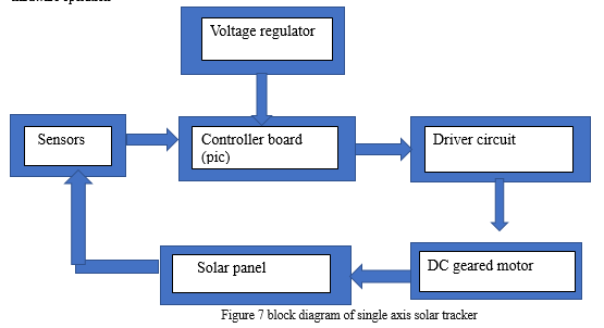
- Microcontroller or Microprocessor: A microcontroller or microprocessor serves as the core component of the control circuit. It receives inputs from sensors, processes the data, and generates control signals to drive the actuators. Common microcontrollers used in solar trackers include Arduino, PIC, or STM32.
- Sensors: Sensors are used to detect the sun's position and intensity. Light-dependent resistors (LDRs), photodiodes, or sun position sensors can be employed for this purpose. These sensors convert light intensity or angle information into electrical signals that are processed by the microcontroller.
- Motor Drivers or Actuator Control Circuits: Motor drivers or actuator control circuits are used to interface the microcontroller with the actuators. Depending on the design, stepper motor drivers, DC motor drivers, or servo motor control circuits can be employed. These circuits receive control signals from the microcontroller and regulate the movement of the actuators accordingly.
- Power Supply and Voltage Regulation: The control circuit requires a stable power supply to operate reliably. A power supply unit is used to provide the necessary voltage levels for the components in the circuit. Voltage regulators can also be included to ensure consistent and regulated voltage for the control circuit.
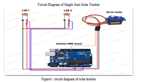
8. Solar Panel: The solar panel utilized in the single-axis solar tracker project is a 20-watt monocrystalline photovoltaic (PV) module. Monocrystalline solar panels are renowned for their high efficiency and sleek design, making them a popular choice for various applications. The panel's construction involves the use of a single crystal structure, allowing for more efficient electron movement and power generation. With an optimized arrangement of silicon cells, the panel can efficiently convert sunlight into electricity, even under varying lighting conditions. The 20-watt rating of the solar panel signifies its peak power output under standard test conditions, providing a consistent and reliable energy source for the single-axis tracker. The module's compact size and lightweight nature make it well-suited for integration into the tracking system, enabling seamless movement along the defined axis. The panel's electrical characteristics, including its voltage-current curve and power output curve, are essential considerations for effectively integrating it within the tracker's control system.
9. Light Dependent Resistor (LDR): A light dependent resistor is made from semiconductor materials which enable them to have their light sensitive properties. Light dependent resistor is very sensitive towards light. The resistance of light dependent resistor may change over many order when light shine on it. Significance value of the resistance falling as the level of light shine on the light dependent resistor increases. The lighting sensor is composed the fixed resistor and the light dependent resistor (LDR). Supply voltage is 5V, and the voltage of LDR cannot be connected directly to the controller. So, voltage divider method is applied to read the voltage of LDR. The value of voltage difference between two LDRs is compared to the sensitivity, because the motor cannot be rotated every time on the whole day. The solar tracking system is designed to rotate CW or CCW directions according to the greater level of voltage when the voltages difference of two LDRs. When the voltage difference is greater than or not the sensitivity, the motor rotates to its respective direction.
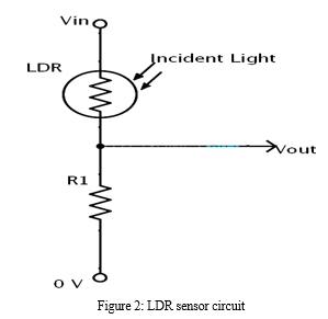
Here are some key points about LDRs in the context of solar tracking systems:
a. Working Principle: LDRs are made of a semiconductor material that exhibits a higher resistance in the absence of light and lower resistance when exposed to light. This characteristic arises due to the variation in the number of charge carriers (electrons and holes) in the semiconductor material under different light conditions.
b. Measurement of Sunlight Intensity: LDRs are utilized in solar tracking systems to measure the intensity of sunlight falling on the solar panels. The photocell to be used for the tracker is based on its dark resistance and light saturation resistance. The term light saturation means that further increasing the light intensity to the CdS cells will not decrease its resistance any further. Light intensity is measured in Lux. The illumination of sunlight is approximately 30,000 lux. They are positioned to face the sky and capture the incident light. The resistance of the LDR changes proportionally with the intensity of light falling on its surface. The amount of light can be measured using an LDR. This is one kind of resistor whose values dependent on the amount of light that hits it. The relationship between the resistance and the amount of light is expressed by
R =500/????,Where R and L are resistance and light intensity, respectively.
c. Integration with Solar Tracking Systems: LDRs are typically connected to an analog input channel of a microcontroller, such as Arduino, which reads the resistance values and converts them into corresponding digital values. These readings are then used by the tracking system to determine the optimal position of the solar panels based on the intensity of sunlight. Overall, LDRs provide a cost-effective and accessible solution for measuring sunlight intensity in solar tracking systems. Their integration enables the system to continuously monitor and adjust the solar panel position, maximizing energy capture and optimizing the efficiency of solar power generation.
Table 1: Specifications of LDR
|
Brand |
Generic |
|
Light resistance |
10K Ohm @ 10Lux |
|
size |
8 mm (dia.) |
|
Dark resistance |
1.0M Ohm @ 0 Lux |
|
Max.voltage |
150 volt |
|
Max.power |
100 mW |
|
No of pins |
2 |
A. Servo Motor
Servo motors are used for various applications. They are normally small in size and have good energy efficiency. The servo circuitry is built inside the motor unit and comes with a position-able shaft that is fitted with a gear. The motor is controlled with an electric signal that determines the amount of shaft movement. When the shaft of the motor is at the desired position, power supply to the motor is stopped. If the shaft is not at the right position, the motor is turned in the right direction. The desired position is sent through electrical pulses via the signal wire. The speed of the motor is proportional to the difference between the actual position and the position that is desired. Therefore, if the motor is close to the desired position, it turns slowly. Otherwise, it turns fast.
A servo motor can be operated with power supply from 4.8V to 6V. Normally voltage of 5V with operating frequency, f0 = 40Hz is used. Servo motor is used to give accurate angle control such as 45 degrees, 90 degrees. The angle can be hold continuously. It can rotate from 0 degree to 180 degrees when the pulse duty ration changed. Servo motors are a type of rotary or linear actuators that provide precise control of angular or linear position, velocity, and acceleration. They are widely used in various applications, including robotics, automation, industrial machinery, and in the context of this research, solar tracking systems. In solar tracking systems, servo motors are used to adjust the position of the solar panel based on the feedback from sensors, such as Light Dependent Resistors (LDRs). The servo motor receives control signals from the system's controller, which calculates the optimal angle for the solar panel based on the sunlight intensity readings. The servo motor then rotates the panel to align it with the sun's position, ensuring maximum exposure to sunlight throughout the day. Overall, servo motors provide precise control of motion and are an essential component in solar tracking systems. Their ability to accurately position the solar panel according to the sun's movement enhances the efficiency and energy output of solar power systems.
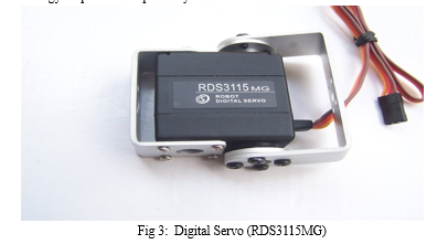
Table 2: Specifications of Servo motor
|
Brand |
DS servo |
|
Weight(gm.) |
55 |
|
Operating Voltage (VDC) |
4.8 ~ 7.2 |
|
Operating Speed @4.8V |
0.16sec/60° |
|
Operating Speed @6.6V |
0.14sec/60° |
|
Stall Torque @ 4.8V (Kg-Cm) |
13.5 |
|
Stall Torque @6.6V (Kg-Cm) |
15 |
|
Operating Temperature (°C) |
-35 to 60 |
|
Dead Band Width ( us) |
1 |
|
Gear Type |
Metal |
|
Rotational Degree |
180º |
B. Arduino Microcontroller
The Arduino microcontroller is a popular open-source hardware platform widely used in various applications, including solar tracking systems.
Introduction: Arduino boards are based on microcontrollers, which are compact integrated circuits that contain a CPU (Central Processing Unit), memory, and other essential components for running programs. Arduino boards provide a user-friendly interface and a simplified programming environment, making them accessible to both beginners and experienced developers.Arduino boards are commonly used in solar tracking systems to interface with sensors such as Light Dependent Resistors (LDRs) or other light sensors. The analog input pins of the Arduino can read the analog voltage values from the sensors, which are then processed and used for controlling the servomotor or other components in the solar tracker system.The Arduino microcontroller serves as the central control unit of the system. It receives the analog voltage readings from the LDRs through the analog input pins. The Arduino board performs analog-to-digital conversion on the sensor readings, converting them into digital values that can be processed by the microcontroller. The Arduino executes a control algorithm that calculates the desired position of the solar panel based on the LDR readings. This algorithm can be based on simple threshold comparisons or more complex algorithms considering environmental factors, such as shading or cloud cover. The control algorithm determines the appropriate position for the solar panel to align it with the sun's position. The servomotor receives the control signals from the Arduino and adjusts its position accordingly. It is responsible for physically rotating the solar panel to align it with the desired position based on the sun's movement. The servomotor can be a DC servomotor with appropriate torque and speed specifications to meet the requirements of the solar tracking system. The solar panel is mounted on a mechanism connected to the servomotor. The servomotor's rotation moves the solar panel, allowing it to track the sun's movement throughout the day. The solar panel's alignment is adjusted to maximize the incident sunlight and optimize energy generation.
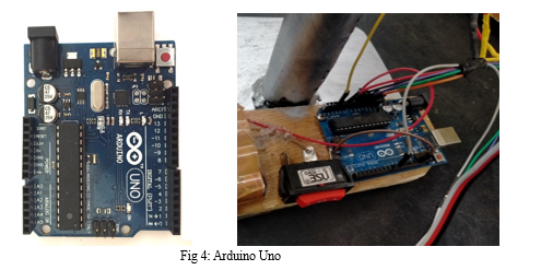
Table 3: Specifications of Arduino
|
Microcontroller |
ATmega328P – 8 bit AVR family microcontroller |
|
Operating voltage |
5V |
|
Recommended Input Voltage |
7-12V |
|
Input Voltage Limits |
6-20V |
|
Analog Input Pins |
6 (A0 – A5) |
|
Digital I/O Pins |
14 (Out of which 6 provide PWM output) |
|
DC Current on I/O Pins |
40 mA |
|
DC Current on 3.3V =-031in |
50 mA |
|
Power |
Vin, 3.3V, 5V, GND |
C. Power Supply
In this project, we directly harness solar energy to power the Arduino-based solar tracker system. The solar panel generates a direct current (DC) voltage, which we efficiently convert into the appropriate power supply for the Arduino. This direct conversion approach eliminates the need for additional batteries or external power sources, making the system more sustainable and self-sufficient. The solar panel's output voltage is regulated and conditioned to meet the specific voltage requirements of the Arduino, ensuring stable and reliable operation under varying solar conditions. This innovative power supply method contributes to the overall efficiency and eco-friendliness of the solar tracker, aligning with the goal of maximizing energy utilization while minimizing environmental impact. We have implemented a direct power supply method for the Arduino-based solar tracker system, utilizing solar energy as the primary source. This approach involves a seamless connection between the solar panel and the Arduino, achieved through the strategic use of a diode and a connector.
The solar panel generates a direct current (DC) voltage output from the captured solar energy. To effectively harness this energy for the Arduino's power requirements, we have introduced a diode into the circuit. The diode acts as a one-way valve, allowing the flow of current from the solar panel to the Arduino while preventing any backflow or reverse current that might otherwise affect the solar panel's performance. This ensures the efficient utilization of solar energy while safeguarding both the solar panel and the Arduino.
III. SOFTWARE IMPLEMENTATION:
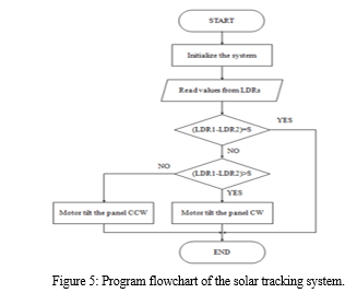
A. Program Flowchart of the System
Firstly the header files, the variable, input and output pins are considered to initialize. Then the data from LDRs are read. The difference between the two LDR and sensitivity are compared. If the measured difference between the set of sensors is greater than the sensitivity value, the direction pin on Arduino is HIGH. The motor rotates CW direction. Or the direction pin on Arduino is LOW and the motor rotates CCW direction.
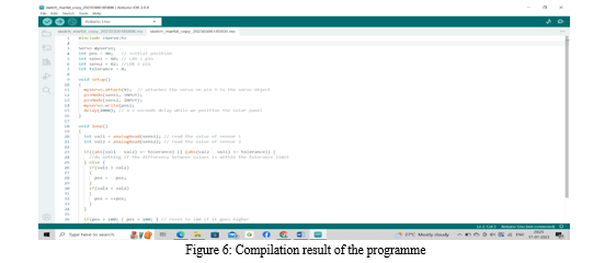
B. Simulation and Compiling
To simulate and compile the whole system, Arduino IDE software is established. Figure 4.2 shows the test result of compiled code is succeeded.
IV. METHODOLOGY
The single axis solar tracking system rotates from east to west keeping the face of the solar panel towards the sun throughout the day. This is achieved using two LDRs and a servo motor interfaced with Arduino. Servo motor is coupled to the panel through an axle. One LDR is placed at the east side of the panel and the other one is placed at west side. LDR is an active sensor which senses light intensity and its resistance increases with increase in the intensity of light. LDRs acts as input, sensing the intensity of the sun. As the intensity falling on the west side LDR increases than the east side LDR (as the day progresses, the sun will be rotating towards west), the servomotor will rotate the panel towards west direction. An assembly language is utilized and saved into Arduino to achieve the rotation as stated earlier. The software part of the system can be split into two parts. The first part is initial positioning. Prior to powering up the system, the panel must be set towards the east, after the sunset and before the next sunrise. The second part deals with the actual movement of the panel, this is the heart of the program. Once the initial position of the panel is set, it is ready to align itself more preciously by continuously tracking the sunlight intensity. The compiled program controls the whole hardware operation
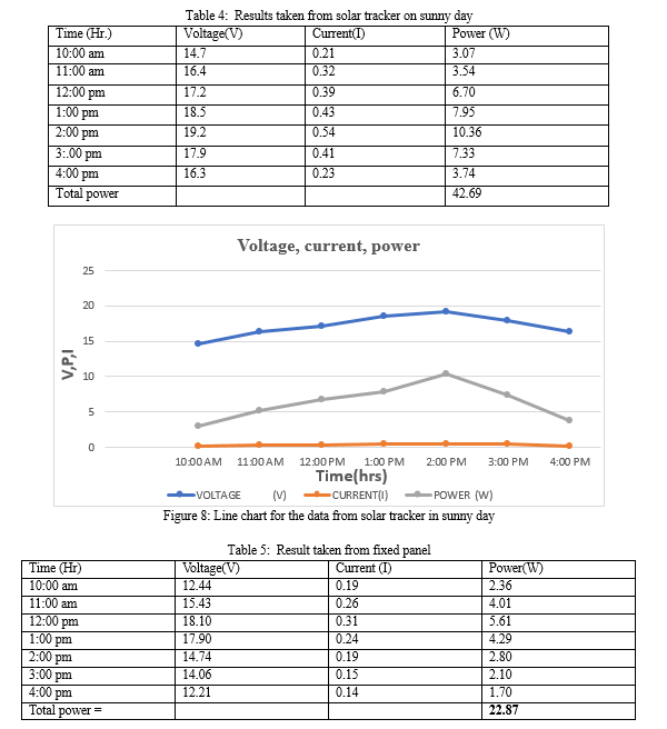
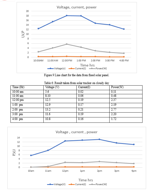
This section explained the result of outdoor testing. Outdoor testing has been done to show the functionality of the single axis solar tracker system towards sunlight. The outdoor testing takes place at College of Agricultural Engineering, SKUAST-K, Shalimar Srinagar (J&K). The experiment was conducted during the month of July – August 2023.SKUAST-K is situated at latitude 34.1494° N and 74.8722° E longitude and 1550 m above mean sea level (MSL). The testing is done only if the weather is in good condition. Comparison of power, voltage, current and efficiency between static solar panel with fixed angle and solar tracker with variable angles has been taken. Data and analysis is taken from 1000 hours until 1600 hours.
V. FUTURE SCOPE
As the proposed prototype is a miniature of main system, it has some limitations which can be mitigated through future developments. A small cardboard is rotated in the system and 19.25v solar panel is used for analysis. As a miniature system, it works out well. Larger Solar panel must be integrated with the system to prepare better result and cost analysis. It has been proven through our research and statistical analysis that solar tracking system with single-axis freedom can increase energy output by approximately 20%.Further mechanical enhancement can be done to the prototype, to implement dual-axis tracking.
Conclusion
An Arduino based single axis solar tracking system was designed and constructed in the current work. LDR light sensors were used to sense the light intensity of the sun with the help of the photovoltaic cells. The servo motor had enough torque to drive the panel. Servo motors are noise free and are affordable, making them the best choice for the project. The compact, cost effective and reliability of this solar tracker is intended to suitable for the rural usage. The purpose of renewable energy from this work offered advance in idea to help the people. This system can be designed to provide electricity to the entire home by changing solar panel, using more efficient sensors and designing the charge controller. Instead of single axis tracker, dual axis tracker are also performed and compared to the single axis. Solar car and solar motorbike can be developed for pollution problems without using resource from the world.
References
[1] Aung, E.E., 2019. Single Axis Solar Tracking System. Int. J. Sci. Eng. Appl, 8, pp.283-286. [2] Aigboviosa, A.P., Anthony, A., Claudius, A., Uzairue, S., Timilehin, S. and Imafidon, V., 2018, September. Arduino based solar tracking system for energy improvement of PV solar panel. In Proc. Int. Conf. Ind. Eng. Oper. Manag (Vol. 2018, pp. 2469-2478). [3] Alijanov, D.D. and Topvoldiyev, N.A., 2021. Solar tracker system using arduino. Theoretical & applied science, 101, pp.249-253. [4] Anne Rosenblatt, Nicole Aaron. 2014. \"SOLAR TRACKING SYSTEM’, Project Report for Swarthmore College Engineering Department. [5] Alijanov, D.D., & Boltaboyev, I.M. (2020). Photosensitive sensors in automated systems. Internauka: elektron. Much. Jurn. ? 23(152) [6] Damm, J. 1990. “An active solar tracking system\", HomeBrew Magazine, Issue # 17. [7] Deepthi S, Ponni A, Ranjitha. R, R Dhanabal, “Comparison of Efficiencies of Single-Axis Tracking System and Dual-Axis Tracking System with Fixed Mount”, International Journal of Engineering Science and Innovative Technology (IJESIT), Volume 2, Issue 2, March 2018. [8] Das, K., Ghosh, H. and Sengupta, M., 2016. Single axis solar tracking system using microcontroller (atmega328) and servo motor. International Journal of Scientific and Research Publications, 6(6), pp.486-489. [9] Kulkarni, A., 2021. Single Axis Solar Tracking System Using Arduino. Available at SSRN 3853506. [10] Kumar Lokhande. 2014. \"AUTOMATIC SOLAR TRACKING SYSTEM\", International Journal of Core Engineering & Management (IJCEM), Volume 1, Issue 7 [11] Oloka Reagan Otieno, 2009. \"SOLAR TRACKER FOR SOLAR PANEL\", University Of Nairobi.
Copyright
Copyright © 2024 A. A. Balkhi, G. M. Mir, Shafqat Bashir, Riyaz Ashraf. This is an open access article distributed under the Creative Commons Attribution License, which permits unrestricted use, distribution, and reproduction in any medium, provided the original work is properly cited.

Download Paper
Paper Id : IJRASET63750
Publish Date : 2024-07-24
ISSN : 2321-9653
Publisher Name : IJRASET
DOI Link : Click Here
 Submit Paper Online

