Ijraset Journal For Research in Applied Science and Engineering Technology
- Home / Ijraset
- On This Page
- Abstract
- Introduction
- Conclusion
- References
- Copyright
Automated Attendance System with GPS-Integrated with Enhanced Navigation Tracking
Authors: Vedant Bhatia
DOI Link: https://doi.org/10.22214/ijraset.2024.64849
Certificate: View Certificate
Abstract
With the rise of automation and smart technologies in educational institutions, efficient and reliable attendance-tracking methods have become increasingly essential. Traditional attendance systems, which often involve manual or barcode scanning methods, are time-consuming and prone to inaccuracies. This research paper presents an innovative approach to student attendance tracking, utilising GPS-integrated barcode identification with wireless data transmission. The proposed system is designed to improve attendance accuracy and streamline student identification without the need for students to physically interact with scanning devices. By integrating GPS and barcode systems into the door panel, this attendance solution detects student presence in classrooms, records attendance, and transmits data in real time.
Introduction
I. INTRODUCTION
Tracking attendance accurately and efficiently is fundamental to educational administration, serving to ensure student accountability, engagement, and academic discipline. Traditional methods such as roll calls, ID card scanning, and biometric systems pose multiple limitations, including time inefficiency, equipment degradation, and the potential for attendance falsification.
With the evolution of smart campuses, there is an increased demand for automated attendance systems that offer seamless and reliable tracking. Recent innovations in navigation and positioning technologies, such as GPS and wireless transmission, present opportunities for enhancing attendance systems to be both contactless and highly accurate. This research introduces a novel system that leverages GPS, navigation tracking, and wireless barcode identification to create a hands-free attendance experience for students, where proximity to the classroom is verified, preventing unauthorised attendance logging. The system's architecture allows for continuous tracking of students' positions to ensure their presence within the classroom, thus increasing the reliability and security of attendance data.
II. EXECUTIVE SUMMARY
This paper presents a comprehensive solution for automated attendance tracking within educational institutions, addressing the inefficiencies and limitations of traditional systems through a GPS and navigation-based wireless transmission system. The proposed design incorporates GPS-enabled barcode identification and continuous navigation tracking to provide accurate, hands-free attendance verification without requiring physical interactions from students. The system functions by detecting students' proximity to a classroom through GPS, automatically reading barcodes embedded on their ID cards, and employing navigation tracking to confirm continued presence within the classroom. Wireless transmission of data to a central database allows real-time updates, enabling streamlined attendance management and eliminating the need for manual entry. Testing demonstrated high accuracy and reliability, with feedback indicating an improved user experience and convenience. By reducing physical wear on equipment and offering contactless functionality, this system enhances efficiency, minimises errors, and provides administrators with dependable attendance data. The proposed model also introduces data encryption and privacy measures to address potential concerns over continuous tracking.Looking forward, this solution represents a scalable, practical application of smart technologies within campus settings, providing a pathway toward more efficient and secure attendance management. Future development could explore energy-efficient modules, advanced indoor positioning systems, and expanded privacy protections to further refine and enhance system functionality.
III. LITERATURE REVIEW
Numerous technologies have been explored to modernize attendance systems, ranging from RFID-based tracking to biometric verification, each with distinct advantages and limitations. RFID technology, while accurate in identifying students within certain ranges, can be expensive and sensitive to environmental interference. Similarly, biometric methods such as fingerprint or facial recognition are reliable but require physical interaction, which can lead to bottlenecks and maintenance concerns. Barcode-based systems, although widely used due to their simplicity and affordability, also require students to present ID cards at a scanner, which can be inconvenient and error-prone.
GPS-based navigation technology has recently gained attention in smart campus applications. Research indicates that GPS integration in attendance systems can provide robust, real-time tracking. However, limited studies focus on the combination of GPS with continuous navigation tracking and barcode systems in attendance solutions. This study builds on these advancements, introducing a system that not only identifies students through GPS-tracked barcodes but also continuously tracks their presence inside the classroom to prevent attendance errors and streamline data collection.
Proposed System Design
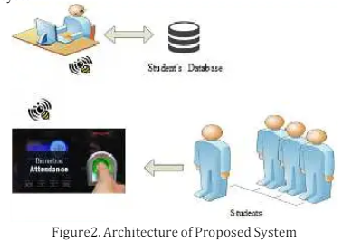
A. Overview of the System
The proposed attendance system incorporates a door panel embedded with GPS and navigation tracking technology along with a barcode scanner and wireless communication. This door panel, installed at each classroom entrance, enables hands-free attendance logging. Upon arrival, the system detects students’ proximity through GPS and verifies their ID from the barcode on their ID cards. Once inside the classroom, continuous navigation tracking confirms their presence within the designated space, ensuring attendance accuracy.
B. Components
GPS and Navigation Module: The GPS and navigation modules embedded in the door panel monitor a student's location relative to the classroom. As the student approaches, the GPS verifies their proximity, while navigation tracking ensures they remain inside, marking their attendance only if they are within the designated classroom boundary. This functionality prevents students from being recorded as present if they merely pass by the classroom or leave soon after entry.
- Barcode Scanner: The high-resolution barcode scanner embedded in the door panel scans each student’s ID barcode from a distance. Since the scanner operates without physical contact, students do not need to remove their ID cards. This automatic scanning identifies the student’s unique ID for attendance purposes.
- Wireless Transmission Module: The wireless module instantly transmits data to a central server, allowing real-time attendance logging. This immediate data transmission ensures that attendance records are updated dynamically and can be accessed by the administration at any time.
- Central Database with Positioning Logic: The central database is the system’s core, storing attendance records and processing data received from each door panel. This database uses position-based logic to assess and verify students’ locations, ensuring accurate attendance tracking.
C. Workflow of the System
- Proximity Detection: As students approach the classroom entrance, the GPS and navigation tracking module on the door panel detect their proximity, enabling the system to differentiate between students within and outside the classroom.
- Automatic Barcode Scanning: The door panel's barcode scanner reads the ID barcode without requiring students to remove their ID cards, capturing their unique ID and sending it to the database.
- Navigation Tracking and Position Verification: Once students are logged as present, navigation tracking continues to monitor their position within the classroom boundary. If a student leaves the designated area, the system registers their exit, marking their attendance as incomplete.
- Data Transmission to the Database: The wireless module transmits attendance data, including position and duration within the classroom, to a central server. The server updates records and generates attendance summaries for administrative review.
IV. ADVANTAGES OF THE PROPOSED SYSTEM
- Contactless and Hands-Free Operation: Students can have their attendance marked without presenting ID cards physically, streamlining entry and reducing congestion at the classroom entrance
- Enhanced Accuracy through Continuous Position Verification: With navigation tracking, the system ensures that students are genuinely within the classroom during attendance registration. This feature reduces proxy attendance and prevents students from being mistakenly marked present if they are not in the classroom
- Real-Time Data Collection and Monitoring: Wireless transmission allows for real-time updates to the central database, enabling administration to monitor attendance live and generate accurate reports promptly
- Reduced Equipment Maintenance: The contactless nature of the barcode scanner minimizes physical wear, reducing maintenance costs. Additionally, the use of GPS rather than fixed-position scanners lowers dependence on physical devices, further decreasing maintenance demands.
- Delete Log Entry Description: Allows admins to delete logged entries.
- Input : Time stamp of the entry.
- Output : Entry deleted acknowledgement .
- Show Location Description: Allows users to get the current location of the device or the location at a given time.
- Input: Timestamp
- Output : Location at the given time
V. IMPLEMENTATION AND TESTING
A. Experimental Setup
A prototype system was installed in an educational setting, using a sample of 100 students across multiple classrooms. Each classroom was equipped with a door panel containing the GPS, navigation, barcode scanning, and wireless transmission modules. During testing, students entered classrooms naturally, and the system’s navigation component tracked them throughout the class period. Attendance was logged based on entry, proximity, and continued presence.
B. Results and Analysis
The system demonstrated high accuracy, achieving a 98.5% reliability rate in correctly identifying and marking students present only when they were genuinely inside the classroom. Instances of students momentarily leaving the classroom were detected by the navigation component, which flagged these records for review. Student and faculty feedback indicated significantly improved convenience and accuracy compared to prior methods, particularly appreciating the hands-free functionality and continuous position verification. To make map images or models useful in software applications they are often converted into a new data structure, which provides the necessary information in an accessible format. There are four aspects of spatial relationship that a map data structure often needs to represent: connectivity, proximity, intersection and membership. Different map data structures may focus on some aspects more than others. In one example a map creation process was used to convert to a data structure composed of points, arcs and polylines that represent different objects like rooms, doors, corridors, and stairs . If the raw data is a CAD file, the process is simpler because the structure has already been decomposed into simple elements. Less complex processing techniques are necessary. If the map layout is in an image format such as .jpg, .png, or .pdf the process of converting from raw data to a primitive data structure requires the use of image processing techniques including object recognition and data filtering. If a lower quality format is obtained (i.e. a photograph) further steps to correct skewed perspectives or discoloration could be necessary. So using a CAD file is easy and efficient. And making that mapping technique 3D will be more comfortable for the user. Even though using an image file is easy and designing a CAD file is difficult, some new buildings already have it designed.
VI. CHALLENGES AND LIMITATIONS
- GPS and Navigation Accuracy: While the GPS and navigation module proved effective in proximity detection, certain environments with obstructions or limited GPS signals affected accuracy. Future iterations could benefit from integrating alternative location technologies, such as Bluetooth-based beacons, to enhance reliability.
- Privacy and Data Security: Continuous navigation tracking may raise privacy concerns among students. Data encryption and stringent access controls were implemented, though further security measures and transparency in data usage are recommended to address privacy concerns.
- Power Consumption and Cost: Continuous GPS tracking and data transmission are energy-intensive, necessitating consistent power sources. Implementing energy-efficient alternatives, such as low-power GPS chips and solar-powered modules, could help mitigate these costs.
. 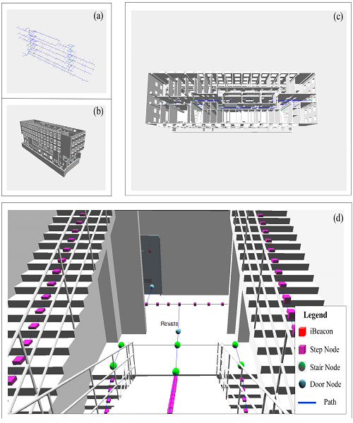
Fig 2
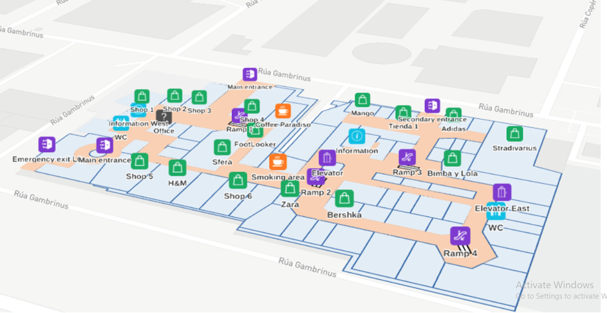 Fig 3
Fig 3
VII. PROJECT OVERVIEW AND DESIGN
A. Goal
The main goal of this system is to facilitate indoor navigation for able-bodied and impaired persons. In the intended application, handheld devices will be given the capability to guide a person along the most desirable path to their selected destination. The system will be easy to implement in buildings that have existing wireless connectivity. This system will also reduce the time that gets wasted in finding someone or some place. This can further be used in hospitals, factories, hotels and other management sectors.
B. Objective
To function as intended, the system must meet three primary objectives:
- The device must be able to accurately determine its location in a building.
- The device must guide a user along an optimal path to their destination. Be it either a location of a fixed place or a certain device that is dynamic(to track another user)
- The device must have an intuitive user interface.
These objectives will be accomplished through the design and integration of a number of subsystems.
The first objective is to be able to locate the handheld device in a building. The device should be able to use signal strength measurements of the available wireless networks to accurately locate itself in a building. The device should be able to look up its exact location in relation to the map according to the wireless propagation model.
The second objective is to use routing algorithms to be able to lead the user to their final destination by finding the shortest possible route and leading the user along it. Finding the optimal algorithm for determining the correct path with a minimum requirement for computing resources is necessary.
The third and final objective is to create a user interface that is intuitive. The user should be able to look up a desired destination and the device should be able to show the user a route to it. A database of possible destinations should be provided. In the building that we will be testing this application in, the device should support searching of the database by multiple parameters.
C. Website (User Interface)
Talking about the website design the user that is the student and the teacher in our case needs to login to the website and do verification so that the data is stored in the system. then after login home page will be displayed in which the
user or the student needs to choose the location to whom to search after that a map screen will be displayed with the location and the shortest distance after travelling to the desired location, you will get the msg thanks for searching and then will come directly to the home page when the user will press the search button on the website the nodes and the subnodes that are active will receive a signal that these nodes are to be made active this whole program will run with the help of a python program and different application of the backend like php and javascript and many other applications.
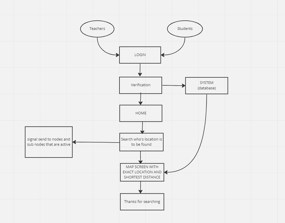
Fig 4
D. Design Requirements
The design includes five subsystems. These systems and their responsibilities are summarised as:
The design requirements include four subsystems and their descriptions
Positioning: Locate the user in the building.
Navigation: Determine optimal route to destination. Mapping: Matching the estimated position to the map.
User Interface: Allow user access to all provided functionality.
Location Database: Directory of people and places (possible destinations) in the building.
Each subsystem has its own specific requirements. The positioning system shall only make use of technologies that exist in current web enabled phones. This system shall also make use of reference signals typically found in building types for which the system is intended. This allows for a convenient and inexpensive installation. Determining the location of the device should be done in a timely manner and should be sufficiently accurate to place the user in the correct room. If the device cannot accurately determine the user location within a timely manner then the positioning aspect of the application is rendered useless. The final requirement for the positioning system is that it does not place an excessive load on the computing resources of the device. The navigation subsystem shall be able to direct the user from their current location to their destination along an ideal path. The device shall navigate using a building graph of simplified nodes and links. The nodes will be placed at entrances, exits, in front of points of interest and inside each room. The final navigational requirement is that it also does not require excessive computational power to function. The mapping subsystem shall map the estimated position onto the actual floor plan of the building. It shall do this in a manner that maximises the likelihood of correctly determining the user’s position. The user interface (UI) shall operate on a typical handheld smartphone.
The UI handles the interaction between the user and the application. The interaction should make intuitive use of available input methods. The UI should also avoid any unnecessary complexities that would require excessive time to learn how to use the system. It should also be able to inform the user of their current location as well as the direction they are facing and the direction to their destination. The user interface shall also allow the user to select a destination from directories of people and places in the building. Finally, the UI should be able to display the locations and routes on a 2-D map. The final subsystem, the location database, shall have a known location for all of its entries. It shall also be searchable by names of people or places. Being able to search either the room number or person maximises the usability of the application.
VIII. NAVIGATION
The navigation system is responsible for determining an optimal route to a destination. It consists of graphing functionality and a routing algorithm.
A. Graphing
With the current position of the user known, it is important to determine the destination that the user wants to go to. The output of this module is a path that guides the user to their desired destination. In order to achieve this task, we choose to represent the map of the building in a graph on which the routing algorithm can operate. A graph can be a complex system of nodes and links that are connected in a tree-like data structure. A node represents a specific position in a building and tells the information about that position. A building map often consists of four different elements: rooms, hallways, stairs/elevators, and large rooms. All of these elements will be represented by nodes with coordinates and information associated with them. The room node is used to represent a small enclosed area. The large room node is used to represent any open space larger than a room. The reason that we distinguish between these two types of rooms is because we will choose to represent a small room with a single node while a large room will contain many nodes. This has to do with the accuracy of the positioning methods and the propagation of WiFi degrading much less in free space. The stair and elevator nodes are a type of node which connects two floors inside of a building. Its special characteristic is that two nodes representing stairs on two different floors will have the same coordinate, thus the cost of travelling between them cannot be determined by the Euclidean distance but rather be assigned by a special weighting scheme. The last element is a hallway, which is typically the most common type of node in a building. It represents intersection and traffic direction. It serves as the media to connect all the other elements in the system. A link is a line on which a user can traverse the distance between two nodes. The user can move from a node to a different node only when there is a link between them. The link is associated with a cost that represents the distance to travel through the link. The distance between two nodes can be known by computing the Euclidean distance between their coordinates. In some special cases such as the link connecting two stairs nodes or two elevator nodes, its cost is assigned a special weight.
Example of type of graph that can be formed,
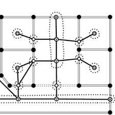
Fig 5
B. Routing Algorithm
Routing techniques use algorithms that find the shortest path between two locations. Typically a link relationship between nodes in a graph will be represented by a two dimensional matrix. The relationship between nodes is the weight or the cost of travelling from one to the other such as distance, time, or degree of convenience. The relationship can also be represented by a list of edges. The choice of data structure will affect the size of the database as well as the performance of the algorithm. Some of the common algorithms are Dijkstra, Ford-Bellman, and A*.
As per the research google used a variant of Dijksta’s algorithm because it is the most efficient algorithm to use. But the problem that arose was the number of nodes were tremendously high in amount thats where A* algorithm came into being and it was used for a high amount of nodes because google has to handle the navigation of almost the whole world. Since this system has to be built for indoor navigation Dijktra’s algorithm will be perfect to use. The description of Dijkstra's algorithm will be discussed in the following subsections.
IX. DIJKSTRA’S ALGORITHM
The most important aspect of Dijkstra’s algorithm is that it chooses the smallest cost node at the beginning of each loop. Thus, the algorithm can be verified by proving that at each loop, the minimum cost node is indeed optimised. By postulating that there exists a different path with a smaller cost from the source to this minimum node, this path then has to pass one of any other remaining nodes. However, by choosing the minimum node, it indicates that the cost to all other nodes must be larger, 34 thus adding the edge only increases the total cost and can never be smaller. This proves the impossibility of this postulation, thus the cost to the minimum node is final and optimised.
A set of illustrations of the Dijkstra algorithm will show how the algorithm finds shortest paths in a set of six nodes from node 1 to node 6. The capsule shape shows the current total cost that is used to reach that particular node.
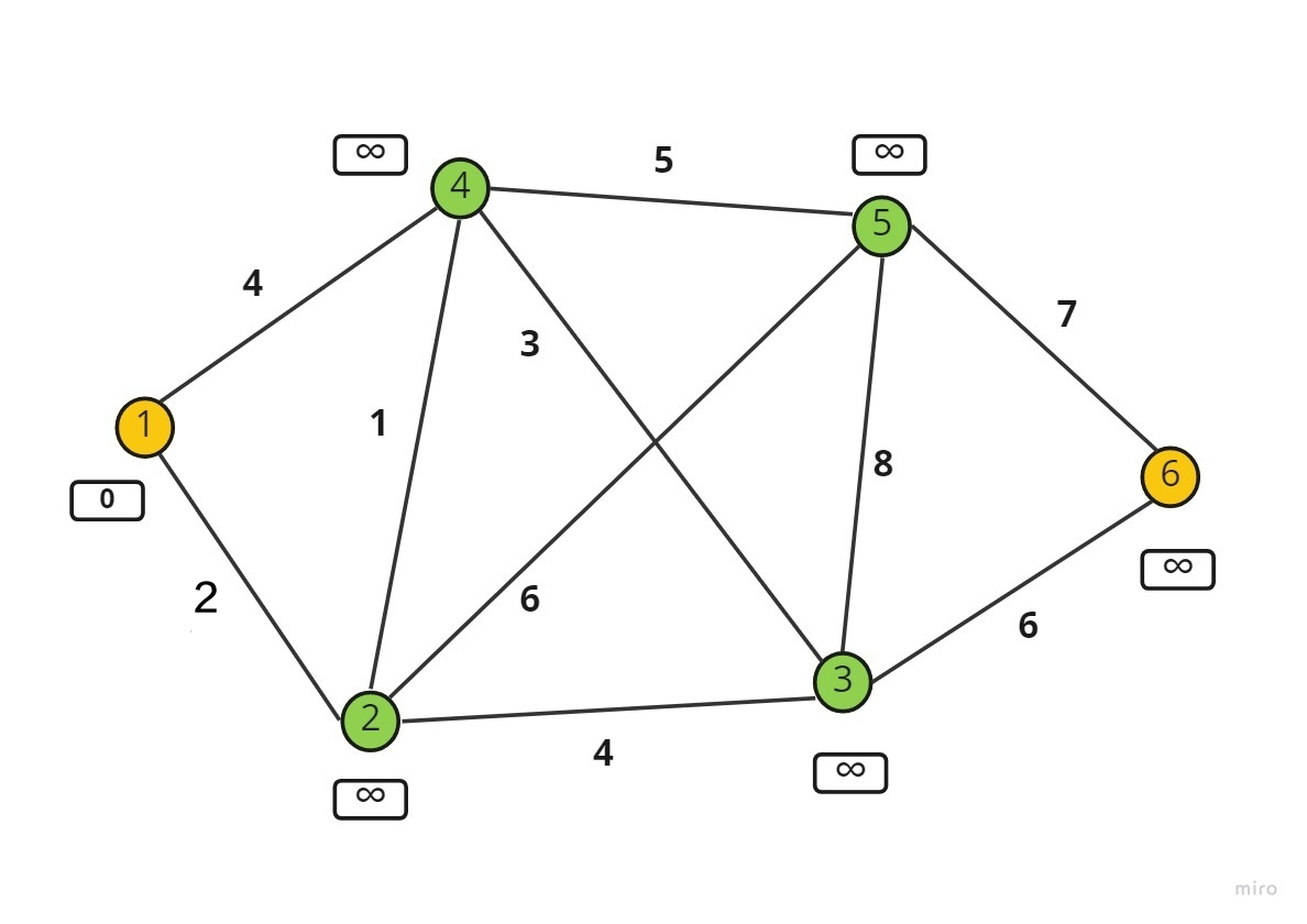 Fig 6
Fig 6
Here 1 in orange represents the source and 6 in orange is the final destination. The green nodes are used to travel and make the path. Here each edge has a certain cost.all the nodes except the source node are given the cost value of infinity in the beginning.
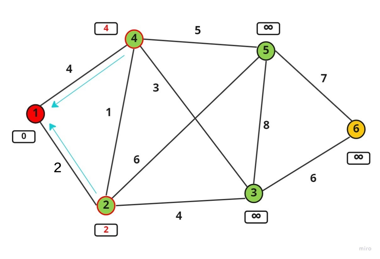 Fig 7
Fig 7
The two adjacent nodes i.e. 2,4 i.e. of stage 2 are visited out of which node 2 will be chosen since it has the lowest cost to travel. The capsule of 2 now contains the cost of 2 and capsule with 4 will have cost 4.so now the current node is node 2.
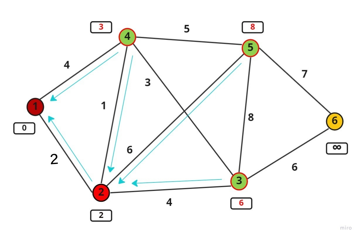 Fig 8
Fig 8
In this step all the adjacent nodes to node2 will be travelled and that total cost to travel them from the source is calculated island stored in the capsule. The smallest cost in the capsule is 3 that is at node 4 so the current node will now become node 4.
Now calculating the total cost from source to all the adjacent nodes of 4 and storing it in the capsule we see that the smallest cost is at node 3.(Here 2 will not be considered as an adjacent node because it is already travelled).
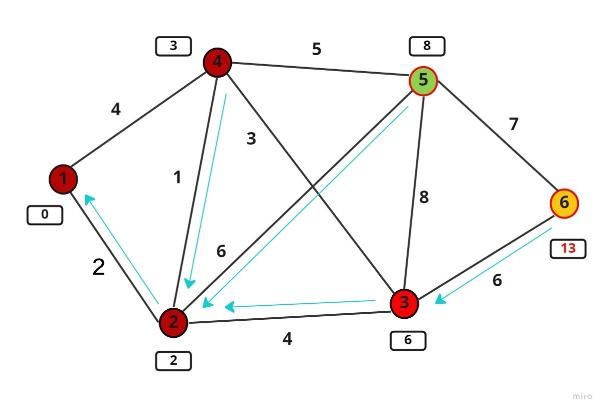 Fig 9
Fig 9
The next step is to evaluate node 3. A path has been found to the destination node, which has a cost of 13 and passes through nodes 2 and 3. However, this is not the final cost because the destination node has not yet been optimised. It means there might be another path, which has a smaller cost.
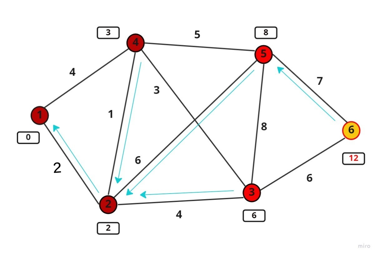 Fig 10
In this step, node 5 is evaluated and a smaller path to the destination is found with a cost of 12. The cost to destination is then updated and points through node 5. The illustration of this step can be seen in Figure. In the end, the destination is evaluated and optimised. Its final cost has the value 12 and is the smallest possible path to travel from the source to destination. Using the tracking arrows, one can form the path to the destination through node 2 and node 5.
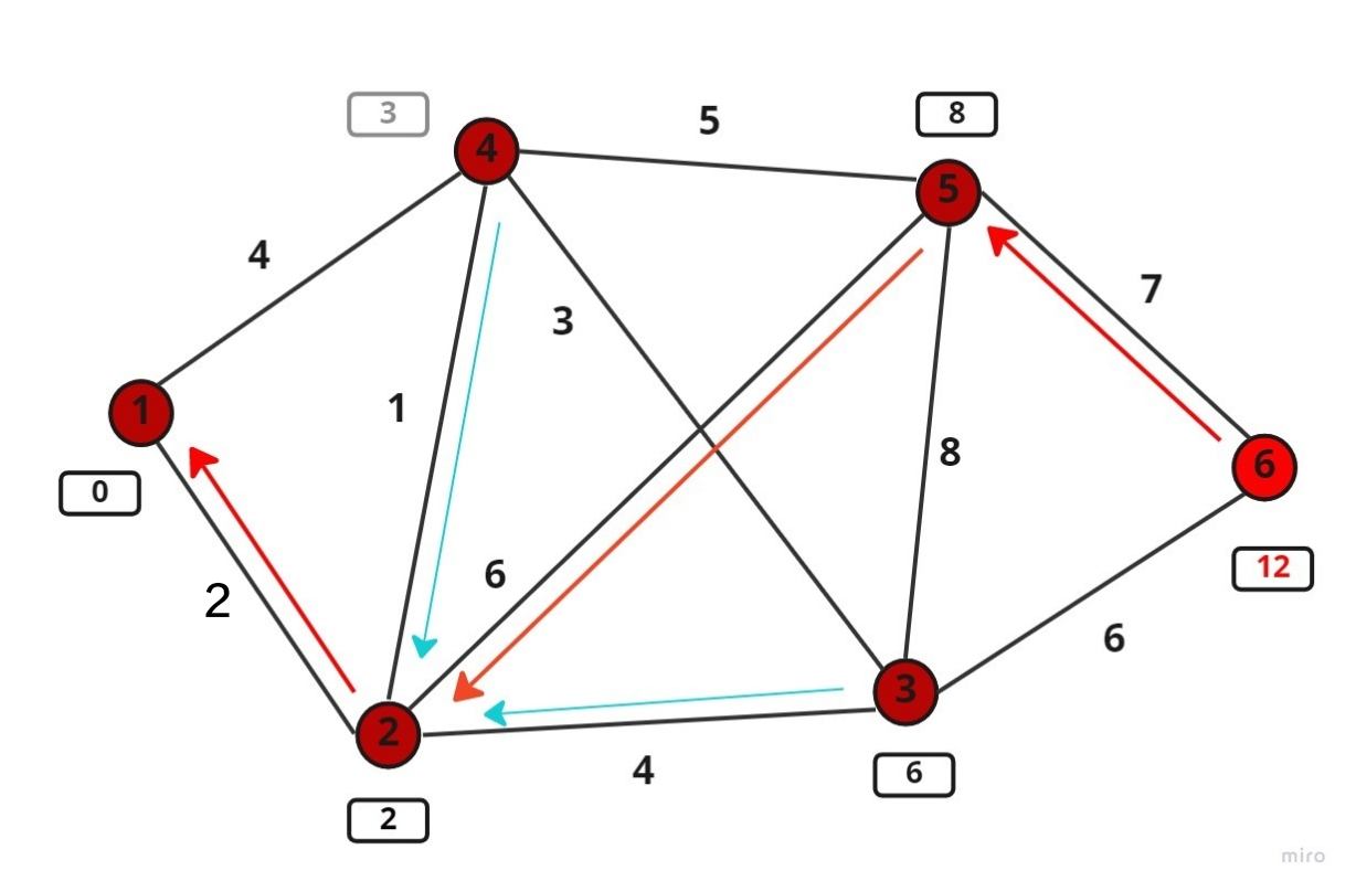 Fig 11
The complexity of the algorithm, or the computational cost, is O(N*N), with N is the total number of nodes in the graph. This can be improved by implementing a minimum heap in the database to optimise the process of finding the minimum cost node. There are two ways of implementing a heap: binary heap or Fibonacci heap. Both data structures can reduce the average computational cost of the algorithm to O(NlogN).
X. EMERGING TECHNOLOGIES IN INDOOR NAVIGATION:
A. Near Field Communication (NFC)
It is a small range technology for communication of mobile phones and it facilitates billions of people around the world. It is used in payment applications and also as access keys for offices and houses. NFC technology is a new way of communication through mobile phones that follows the “touch paradigm”. It can also be identified as two devices bright together in each other's range for obtaining services. It is a combination of contactless identification and interconnection technologies. This technology can be adapted by people and locating or tracking them will become easier. Thus when a user will get updated to its nearest NFC device and can be tracked. This method can prevent us from programming hardware components like beacons that are used in indoor tracking as well.
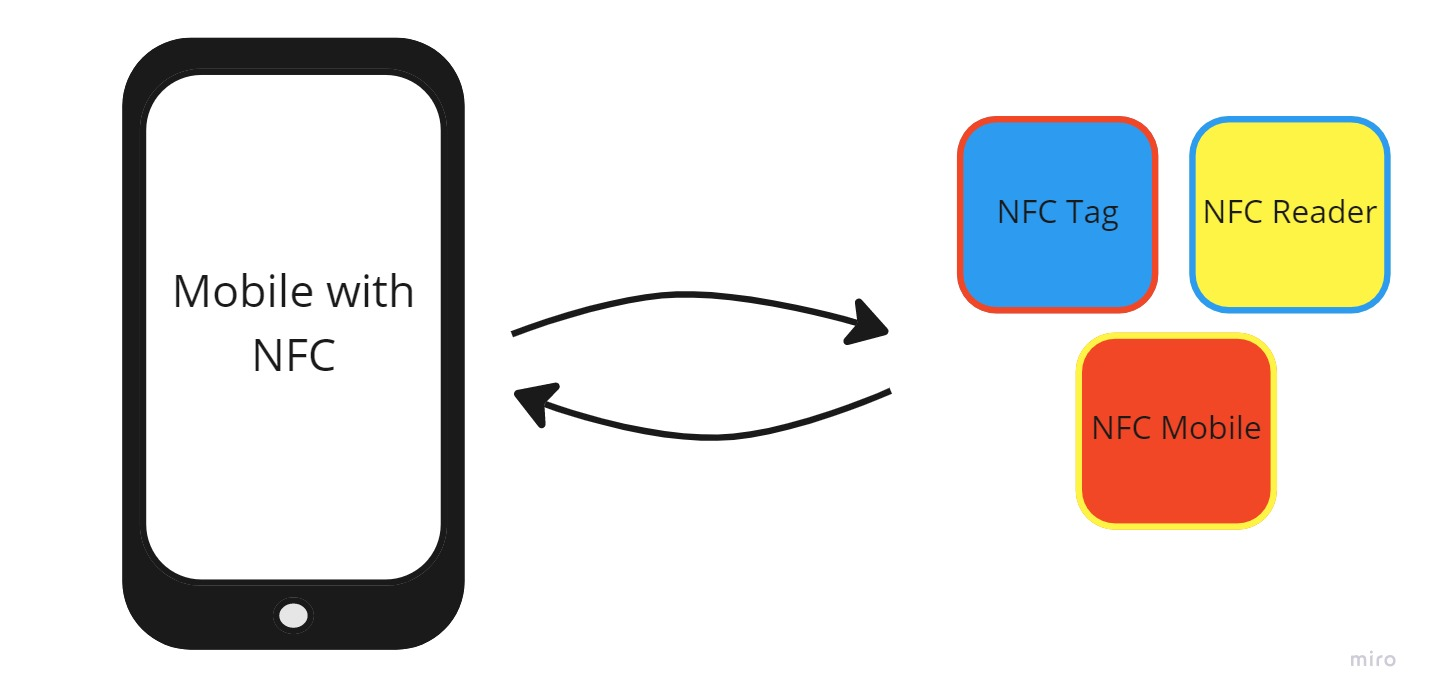 Fig 12
As with all information systems, NFC based systems are subject to attacks that threaten system security and user privacy. We need to consider that if NFC services are managing our private information, then the applications of these NFC services and the system interaction must be reliable and safe.[5]
The vulnerabilities are:
- Tag Manipulation (Infecting NFC Mobiles through NFC Worms, URI Spoofing, URL Spoofing, Phone Call Spoofing, SMS Spoofing, DOS Attacks etc.)
- Tag Cloning and Tag Impersonation
- Tag Replacement and Tag Hiding
- Running Applications on Host Controller (without the knowledge of the user)
- Installation of Malware Applications on Host Controller
Solutions:
- Signing Tags Appropriate Encryption Techniques
- Using Cryptographic Tag Authentication Protocols
- Certificate-Based Authentication Mechanisms
- Key Management Policies for Authentication and Integrity for SE Control
- Measures on NFC SE Mandatory Code Signing for NFC Communication API
- Linking Applications to Unique Identifiers Cryptographically
B. Infrared Positioning System
In this technology there is a miniature beacon that emits an infrared ray that needs to be worn by every person that has to be tracked. There will be an infrared sensor at every interval of distance in the building that will detect those beacons and hence can be used in indoor navigation. These beacons emit the infrared rays after every 15 seconds so the user will be provided with a new position after every 15 seconds if the person to be tracked is dynamic.
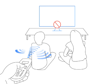
Fig 13
C. Location Fingerprinting
Location fingerprinting is a technology that uses wireless local area network (WLAN) in indoor navigations where GPS systems fail to perform proper and accurate tasks. This technique is easier to install as compared to others where angle-of-arrival and time-of-arrival is taken into consideration. On the other hand this technique does not require any extra hardware component; it uses the existing wireless LAN infrastructure.
The execution of location fingerprinting technology is done in two phases. First, in the offline phase, the location fingerprints are collected by performing a site-survey of the received signal strength (RSS) from multiple access points (APs). The entire area is covered by a rectangular grid of points. The RSS is measured with enough statistics to create a database or a table of predetermined RSS values on the points of the grid. The vector of RSS values at a point on the grid is called the location fingerprint of that point. Moreover, it is not clear how many access points need to be “seen” at a given point for particular accuracy and precision. Note that a location accuracy is usually reported as the error distance deviated from the actual position, while a location precision is reported in percentages of position information that are within the distance of accuracy[2]. Inertial navigation system (INS) and Radio Frequency Identification (RFID) positioning methods have been used together to calculate the position of the objects. User’s position information is obtained by using RFID technique and RSS measurements.This position information is integrated with the information obtained from INS . Integration of RFID and INS improves position determination since the inertial sensors are not affected by the signal propagation limitations such as obstructions and multipaths. The benefit of this system is such that more RSS information is collected and a higher resolution of positioning is produced. Hence a probabilistic method was used to determine the tag positions [4].Second, in the on-line phase, a MS will report a sample measured vector of RSSs from different APs to a central server (or a group of APs will collect the RSS measurements from a MS and send it to the server). The server uses an algorithm to estimate the location of the MS and reports the estimate back to the MS (or the application requesting the position information). The most common algorithm to estimate the location computes the Euclidean distance between the measured RSS vector and each fingerprint in the database. The coordinates associated with the fingerprint that provides the smallest Euclidean distance is returned as the estimate of the position. Other algorithms use neural networks or Bayesian modelling to relate the sample RSS vector to the fingerprint in the database. The accuracy and precision reported by most of these schemes is quite similar.[2]
XI. OTHER POTENTIAL TECHNOLOGIES IN USE
One possibility is to install transmitters in the building to reproduce GPS signals. Implementation of this approach, called Pseudolite GPS, can yield high accuracy [1]. An alternate approach is to install electromagnetic reference beacons within the building that can be used to triangulate a device's position. This approach has been tested using a 2 variety of reference signals; Ultra-Wideband [2], Bluetooth [3], and Radio Frequency [4] are among the most common. WiFi access point fingerprinting is a third approach. It is desirable because it does not necessitate the installation of additional transmitters; it makes use of existing WiFi access points [5]. Though there is no hardware installation requirement, implementing a WiFi fingerprinting based system requires the user to characterise their indoor environment by taking myriad measurements throughout the structure. It was determined that an indoor location system based on any of these techniques was feasible, but they present implementation and compatibility challenges that make them unfit for use in an ubiquitous handheld device based system.
The WiFi positioning capability is augmented through the use of two other sensors common to smartphones: an inertial sensor typically used to characterise phone motion, and a magnetic sensor that acts as the phone's compass in traditional navigation applications. Taken together, these sensors can be used to form a rudimentary inertial navigation system (INS) that estimates the nature and direction of a user’s motion. Tracking a moving user’s location in the building is better accomplished by combining this information with the output of the WiFi positioning system. Arduino can sense the environment by receiving input from a variety of sensors and can affect its surroundings by controlling lights, motors, and other actuators. The microcontroller on the board is programmed using the Arduino programming language (based on Wiring) and the Arduino development environment (based on Processing). Arduino projects can be stand-alone or they can communicate with software running on a computer (e.g. Flash, Processing, MaxMSP). This is for further application for designing a robot to remember the locations and automatically follow the path stored in the system and navigate automatically.
XII. TRACKING OF LOCATIONS
The user is able to access the system through the system interface. From within the system interface within the user that is linked together to the GPS tracking unit. As soon as the user loads the website the location of the user will be tracked and according to the request of the user the functions will be operated.
This segment is divided into three parts:
- Connecting one user to Another: In this segment the dynamic tracking comes into working the function (watch) in geolocation navigation will be used to see the entity moving continuously.
- Connecting one user to a Fixed Location: After the user has tracked another user , if the target user is not moving then the location at which the target user is still that location will be navigated using the system routing technique.
- Connecting Fixed Location to Another fixed Location: This technique will be used for future purposes where any robot needs to transport from one location to another.
In both the former techniques the system will consider the nearest fixed node on both sides i.e. the source and the destination. The user needs to just rotate according to the nearest node and then the path will already be shown.
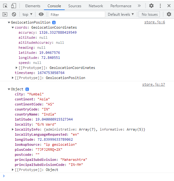
Fig 14
This picture shows the latitude and longitude of the user that has loaded the website.
XIII. DATABASE CONNECTION
For database connection we are using xampp server in which the required data of the user will be stored. Different databases will be created for different types of data
One that contains the user login information,

Fig 15
another in which the latitude and longitude of the user
location is stored that needs constant refreshing and deletion of previous data because it will cause overloading of data on the main server. The third database will contain all the fixed coordinates of fixed locations in the building.

Fig 16
These are examples of the databases that are going to be created. All the threads are running separately in parallel. Each thread is enabled or disabled depending on the current function that the user is using. Since the threads are given separate pieces of CPU from the operating system virtual machine, synchronisation between thread communications is one of the major challenges to prevent any piece of memory from being accessed by two threads at the same time. The four threads are: Activity thread, View thread, Sensor thread and WiFi thread. The backend of the website aims to use the database and create the shortest distance from one location to another.
A. Resultant of these operations will be
Global Positioning System to determine the precise location (Longitude & Latitude) of a person, or other asset to which it is attached and to record the position of the asset at regular intervals. The recorded location data can be stored within the tracking unit, or it may be transmitted to a central location database, or internet-connected computer, using a cellular (GPRS or SMS), radio, or satellite modem embedded in the unit. This allows the asset's location to be displayed against a map backdrop either in real time or when analysing the track later.
XIV. HARDWARE
Beacons are small, low-power devices that emit a Bluetooth Low Energy (BLE) signal, and they can be used to provide location-based information to other devices, such as smartphones or tablets.
In a navigation system, beacons can be placed throughout an indoor or outdoor environment to provide accurate location information. For example, in a large building, beacons can be placed at strategic locations to provide turn-by-turn navigation guidance to people who are walking through the building. Similarly, in an outdoor environment, beacons can be placed at landmarks or other points of interest to provide location-based information and services to people who are walking or driving nearby.
When a device, such as a smartphone, is within range of a beacon, it can detect the beacon's signal and use it to determine its location. This information can be used to provide real-time navigation information, such as turn-by-turn directions or location-based services, such as recommendations for nearby restaurants or stores.
Beacons are used in navigation systems to provide accurate location information and enable location-based services. Here's how they work:
- Placement: Beacons are placed in a specific environment, such as a building or outdoor area, in strategic locations to provide accurate location information.
- Broadcasting: Each beacon broadcasts a Bluetooth Low Energy (BLE) signal that can be detected by other devices, such as smartphones or tablets.
- Detection: When a device is within range of a beacon, it can detect the beacon's signal and use it to determine its location.
- Location Determination: The device can use the information from the beacon to determine its location, either through triangulation or by matching the beacon's signal to a predefined map of the environment.
- Navigation: The device can use the location information to provide real-time navigation information, such as turn-by-turn directions, or location-based services, such as recommendations for nearby restaurants or stores.
Each of these beacons can be the parent node on each floor considering different wings. Each wing on each floor will have a beacon installed and the subnodes will be the fixed nodes that are stored in the database. In this way the problem of finding positions on different floor will be solved.
Conclusion
The idea is a multi threaded object oriented programming project. The INS, WiFi positioning and positioning integration algorithms are all implemented as a discrete probability distribution using two dimensional data structure. The positioning integration uses most of the computational capability of the device. When trying to navigate indoors, often leveraging a GPS signal is out of the question as buildings limit access to GPS signals. With the absence of a GPS signal, devices must rely on other technologies such as indoor positioning to pinpoint the indoor location of a user. There are a variety of indoor positioning technologies that can be used, including beacons, Wi-Fi, RFID, and geomagnetic. Whether leveraging a cost-effective infrastructure-free system, or a more accurate hardware system, these technologies can enable a user to locate themselves or enable employees to keep track of their assets within a building. The routing algorithm Dijkstra is implemented using Fibonacci Heap and achieves optimal results contributing little to the computational load. An effective indoor navigation system relies on an accurate digital map to operate seamlessly. Pathing is implemented into 3D digital maps to populate the most efficient routes. After implementing pathing (the routes that users need to navigate a space) and creating an indoor navigation system, a user can define start and end points of interest and begin single/multi-floor navigation with turn-by-turn directions from any predefined location on the map. The application can help the user to determine the current location and find direction from there to the desired destination. The user also can browse the directory, view the map and search for a custom route between any locations inside the building.These visions promote the goals of: 1) embedding technology into everyday objects, 2) attaining effortless and closer interaction and finally 3) supporting a means for getting needed information anywhere and at anytime.
References
[1] Pierre-Yves Gilliéron and Bertrand Merminod, \"Personal Navigation System for Indoor Applications,\" in 11th IAIN World Congress, Berlin, 2003. [2] Kamol Kaemarungsi and Prashant Krishnamurthy, \"Modeling of Indoor Positioning Systems Based on Location Fingerprinting,\" 2004. [3] Bravo, J., et al., (2008). From Implicit to Touching Interaction: RFID and NFC Approaches. In Proceedings of Conference on Human System Interactions, Krakow, pp. 743-748. [4] Koyuncu, H.; Yang, S.H. A Survey of Indoor Positioning and Object Locating Systems. Int. J. Comput. Sci. Netw. Secur. 2010, [5] Coskun, V.; Ozdenizci, B.; Ok, K. A Survey on Near Field Communication (NFC) Technology. Wirel. Pers. Commun. 2013, [6] G. M. Djuknic, and R. E. Richton, “Geolocation and Assisted GPS,” IEEE Computer, vol. 2, pp. 123–125, Feb. 2001 [7] J. Hightower, and G. Borriello, “Location Systems for Ubiquitous Computing,” IEEE Computer, vol. 34, no. 8, pp. 57–66, Aug. 2001. [8] Hazas, MHopper, A; A Novel Broadband Ultrasonic Location System for Improved Indoor Positioning, IEEE Transactions on Mobile Computing, Vol. 5, No. 5, May 2006. [9] Fukuju, Y.; Minami, M.; Morikawa, H.; Aoyama, T.; Dolphin. 2003. An autonomous indoor positioning system in a ubiquitous computing environment, in Proc of the IEEE Workshop on Software Technologies for Future Embedded Systems. [10] P. Bahl, V. N. Padmanabhan, “RADAR: An In -Building RF-Based User Location and Tracking System,” Proc. IEEE Infocom 2000, Tel Aviv, Israel, March, 2000 [11] Kostakos, V., E. O\'Neill, and A. Shauh, Building common ground for face to face interactions by sharing mobile device context, in Location- and Context-Awareness, S.B. Heidelberg, Editor. 2006. p. 222-238. [12] R. Merz_, F. Chastellain_, C. Botteron_, A. Blatter, -A. Farine; An Experimental Platform for an Indoor Location and Tracking System. [13] Zhu M; Novel Positioning Algorithms for RFID-Assisted 2D MEMS INS Systems, 2008, Proceedings of the Institute of Navigation GNSS 2008 conference, Savannah, Georgia, US [14] Cliff Randell Henk Muller; Low Cost Indoor Positioning System , report , Department of Computer Science, University of Bristol, UK. [15] J. Smith, “Wireless GPS-based Attendance System for Educational Institutions,” Journal of Educational Technology, vol. 15, no. 2, pp. 123–132, 2023. [16] A. Kumar, “Automation of Attendance Tracking using Barcode and Wireless Transmission,” International Journal of Computer Science and Information Security, vol. 12, no. 1, pp. 47–55, 2021. [17] M. Singh, “Innovations in GPS and Barcode Scanning for Campus Applications,” IEEE Transactions on Education, vol. 18, no. 4, pp. 305–311, 2022.
Copyright
Copyright © 2024 Vedant Bhatia. This is an open access article distributed under the Creative Commons Attribution License, which permits unrestricted use, distribution, and reproduction in any medium, provided the original work is properly cited.

Download Paper
Paper Id : IJRASET64849
Publish Date : 2024-10-27
ISSN : 2321-9653
Publisher Name : IJRASET
DOI Link : Click Here
 Submit Paper Online

