Ijraset Journal For Research in Applied Science and Engineering Technology
- Home / Ijraset
- On This Page
- Abstract
- Introduction
- Conclusion
- References
- Copyright
A Review of Battery Cell Equalization Techniques for Use in Real World Applications
Authors: Raynard du Preeza, Christiaan Oosthuizenb, SJ Jacobs
DOI Link: https://doi.org/10.22214/ijraset.2023.48725
Certificate: View Certificate
Abstract
The usable energy available from a lithium-based battery energy storage system is affected by factors both internal and external. One of the most influential and potentially dangerous factors is cell charge deviation. This issue is directly addressable with the use of a battery management system and even more through the use of a cell equalization subsystem. There is a wide variety of cell equalization methods that can be used in low, medium, or high-power applications ranging from residential energy backup systems to electric vehicles and industrial load-shifting grid-tied systems. This paper presents a variety of cell equalization methods and compares each of the distinct cell equalization topologies by evaluating different criteria such as equalization rate, power capabilities, complexity and cost. The result of this comparative study is summarized in a set of comprehensive tables that can serve as a guideline to engineers in selecting the best solution for an application. The use of these comparative tables is also illustrated by looking at different real-world case studies.
Introduction
I. INTRODUCTION
The battery management system (BMS) is a crucial element within any Lithium based energy storage system. These energy storage systems include the battery systems found in electric vehicles (EV), grid-tied energy storage systems, and even high-performance power tools. The main objectives of the BMS are battery protection, keeping the battery in an accurate and reliable state as well as predicting and extending battery life [1]. The BMS achieves these objectives by continuously performing various battery-specific functions. These functions may include that of measurement voltages, temperatures and currents throughout the battery system, the state of charge (SoC) and state of health (SoH) of the cells and the system, thermal management, charge/discharge control, communication with external systems, data acquisition and battery cell equalization [2].
Over time series-connected battery cells will differ in terms of SoC, this imbalance of cells is a vital issue for the life and capacity of a Lithium battery system. The usable capacity of a battery is determined by the lowest and highest charged cells when the battery is in discharging mode and in charging mode respectively. This is due to the under-voltage and over-voltage limits of the Lithium battery cell. The imbalance between cells is caused by internal and/or external factors. Internally cells vary due to minor manufacturing inconsistencies such as internal impedance, charge storage volume, and self-discharge rates. The external factors are mainly due to thermal differences throughout the battery system and external circuitry (protection units) connected to each cell[3].
Battery cell imbalance is corrected through the use of a battery cell equalization/balancing unit that forms part of the BMS. Numerous cell equalization methods have been researched and proposed. These methods are categorized as either passive or active equalization as can be seen in Fig. 1 [4]–[7].

Passive cell equalization methods make use of passive resistors in parallel with the battery cells to remove excess energy from higher-charged cells through heat dissipation. These passive resistors are either fixed in the circuit or can be switched in and out of the circuit[8]–[10]. Active cell equalization methods operate by transferring excess energy from higher-charged cell(s) to lower-charged cell(s). The active cell equalization method can be further divided into three subcategories according to the elements used such as capacitors, inductive storage elements, or converters (controlled switches) [10], [11].
This paper will discuss several cell equalization topologies from both the passive and active cell equalization categories. Firstly, each of the cell equalization topologies will be discussed individually. The focus being respective circuit configurations, basic components required, advantages and disadvantages as well as a brief look at the control strategy for each of the topologies. Previous papers only discussed and compared cell equalization methods at a low level. This paper aims to generate usable information tables that will serve as a guide to engineers to select the most appropriate topologies for an application, thus reducing time spent during the research phase. In this paper, a scaled number-based comprehensive comparison is presented featuring all the cell equalization topologies with regard to equalization rate, equalization efficiency, control complexity, size, cost, application, and circuit design. The addition of case studies will illustrate to the reader how these tables can be used in selecting the best-suited cell equalization topology through the implementation of a simple Pugh method (decision matrix).
II. CELL EQUALIZATION TOPOLOGIES
This section will look at cell equalization methods and the different topologies of each of these methods. The basic operation of each of these topologies will be discussed along with the advantages and disadvantages of each topology.
A. Resistor Based
The resistor-based cell equalization method is the only equalization method classified under the passive cell equalization branch as can be seen in Fig. 1 [8], [10]–[12]. Resistor-based cell equalization methods are the most commonly used topology in a wide variety of Li-Ion battery applications including power tools, electric vehicles, and backup energy storage systems. This is due to the exceptional reliability, simplicity, and ease of integration with new or existing energy storage systems [11]. The resistor-based cell equalization method has two distinct sub-structures namely fixed shunt resistor (FSR) and switched shunt resistor (SSR).
The fixed shunt resistor topology has fixed resistors permanently connected in parallel with each series-connected cell. This topology was designed for lead-acid and nickel-cadmium batteries and is not suitable for Li-Ion batteries. Thus, this topology will not be considered for this paper.
Switched Shunt Resistor (SSR)
The SSR equalization method utilizes a resistor, which can be switched in and out of the circuit to get rid of excess energy through heat dissipation for equalization of the series-connected cells, as shown in Fig. 2 [10]–[12]. The most commonly used design practice is to choose a resistor size so that the dissipating current is equal to or lower than 10mA/h, this is an equalization rate of 1% per hour.

The SSR topology can be coupled with two control strategies, continuous or detect operation. The continuous control strategy involves all the switches being controlled by a single control signal, i.e. all switches are turned on and off simultaneously. As each of the cells have a different voltage level, the power is dissipated through the shunt resistor will be higher for the higher-charged cells. This will result in less charging current flowing to the higher-charged cells. The detect control strategy requires additional components as this strategy relies on the measurements of each cell voltage. The measured voltages are used to identify the cells with higher voltages. The shunt resistors for these higher-charged cells are connected in parallel to the cells through individual switches.
This will allow the lower-charged cells to receive more charge current, thus speeding up the equalization process. The activation time is determined by the voltage difference between the higher and lowest cell voltages.
The control strategy for the detection topology is more complex and more expensive than that of the continuous topology, but it has a quicker equalization rate and is also more efficient.
It is recommended that the SSR topology is used when the battery is in charging mode. This will dissipate incoming energy to the higher charged cells, which will result in a slower charge rate for these respective cells instead of wasting the stored energy within the cells.
B. Capacitor Based
The capacitor-based cell equalization method makes use of external capacitors as an additional storage element to shuffle excess energy between all the series-connected cells in the battery pack. This is a considerable increase in efficiency over the resistor-based topologies as excess energy is not wasted in the form of heat. The capacitor-based cell equalization method has the highest energy efficiency of all the cell equalization methods, close to 99% [4]–[7], [9], [13]. The capacitor-based cell equalization method or “charge shuffling” method can be separated into four topologies or district variants. These topologies are; the switched capacitors (SC), single switched capacitor (SSC), double-tiered switched capacitor (DTSC), and common node switched capacitors (CNSC). Due to the nature of the capacitor, these types of topologies operate in three stages, capacitor charging, capacitor discharging, and dead time. The dead time occurs between each transition from charging and discharging of the capacitors. All of the above-mentioned topologies can operate when the battery is in standby, charging or discharging modes. This does not necessarily mean an increase in equalization rate over the resistor-based topologies, however, unbalanced cells can be addressed more often during operation although the method requires a larger and more complex configuration.
1) Switched Capacitor (SC)
The SC cell equalization topology is capable of working with little to no additional intelligence [14]–[20]. The configuration shown in Fig. 3, shows that for n number of cells, n-1 external capacitors are required with 2n switches. The equalization rate for this topology is the lowest of all (up to 5 times lower than resistor-based topologies), especially in the event where the cells with the highest and lowest charge are on opposite ends of the battery pack as seen in Fig. 3.

All the capacitors are activated and deactivated (charge/discharge) simultaneously, as a result during the active state the capacitors will charge to match the voltage of the respective parallel cells. This means that each of the higher-charged cells will transfer more energy to its respective parallel capacitors than the lower-charge cells. This is followed by the capacitors then transferring the stored energy to the neighbouring (possibly lower-charged) battery.
2) Double Tiered Switched Capacitor (DTSC)
The DTSC topology is an evolution of the basic SC topology, with an additional capacitor added to a second tier [21], [22]. The basic operation of this topology is similar to that of the switched capacitor topology, with all first-tier capacitors switched in and out of the main circuit simultaneously. The second-tier capacitor functions as a bridge between non-adjacent battery cells, allowing energy to be transferred via the bridge, thus significantly reducing the equalization time.
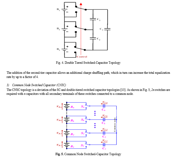

This topology requires a non-complex control strategy that identifies the highest and lowest charged cells. The corresponding switches are then activated and deactivated in turns starting with the higher-charged cell followed by the lower-charged cell. Thus, energy is transferred directly between any two cells. In the event all cells are equally charged, no charge shuffling will take place, thus increasing efficiency.
C. Inductive Base
The inductive base cell equalization methods can be subdivided based on the main equalization element being either an inductor or transformer.
The inductor-based cell equalization method is very similar to the capacitor-based cell equalization method but utilizes inductors as external energy reservoirs rather than separate energy storage elements. The high-side and low-side switches are controlled using pulse width modulation (PWM) signals. The high-side and low-side switches can be active at the same time, with the high-side PWM signal leading to the low-side PWM signal. The advantage of the inductor-based equalization method is a higher equalization current and equalization rate when compared to the previously mentioned resistor-based and capacitor-based methodologies. The disadvantage when compared to the other topologies is the relatively higher capital cost. Similar to the capacitor-based topologies, the inductor-based cell equalization can be divided into the single-switched inductor (SSI) and multi-switched inductor (MSI) topologies respectively.
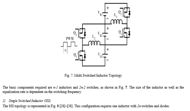
1) Multi Switched Inductor (SSI)
The MSI topology utilizes a common inductor for each set of neighbouring cells. Each set of neighbouring cells is also accompanied by a set of switches which is oppositely controlled with a PWM pulse width modulated) signal. During the first half of the PWM signal (<50% duty cycle), this first switch will close. This causes current to flow, charging the inductor (storing energy), The charge rate is determined by the SoC of each respective cell, higher charge cells will result in higher current flow to the inductor. During the second half of the PWM signal, the first switch will open and the alternative switch will close, discharging the inductor thus transferring the energy to the adjacent cells[28]–[38]. With the addition of a low-level control strategy, energy transfer can be seized once charge equalization is reached.
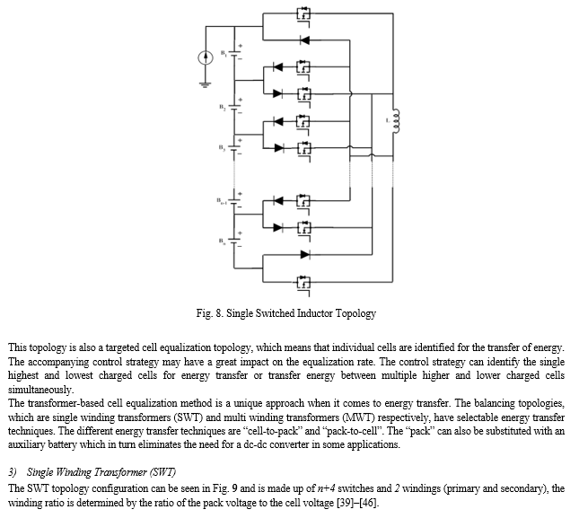

The “fly-forward” structure discharges all cells, with the higher-charged cells transferring energy at a relatively higher current rate. This excess energy is then redistributed across the battery pack. The “fly-back” structure works in reverse fashion with the battery pack being discharged and the energy distributed across each series cell. The lower charged cells will sink energy at a higher current rate.
D. Converter Based
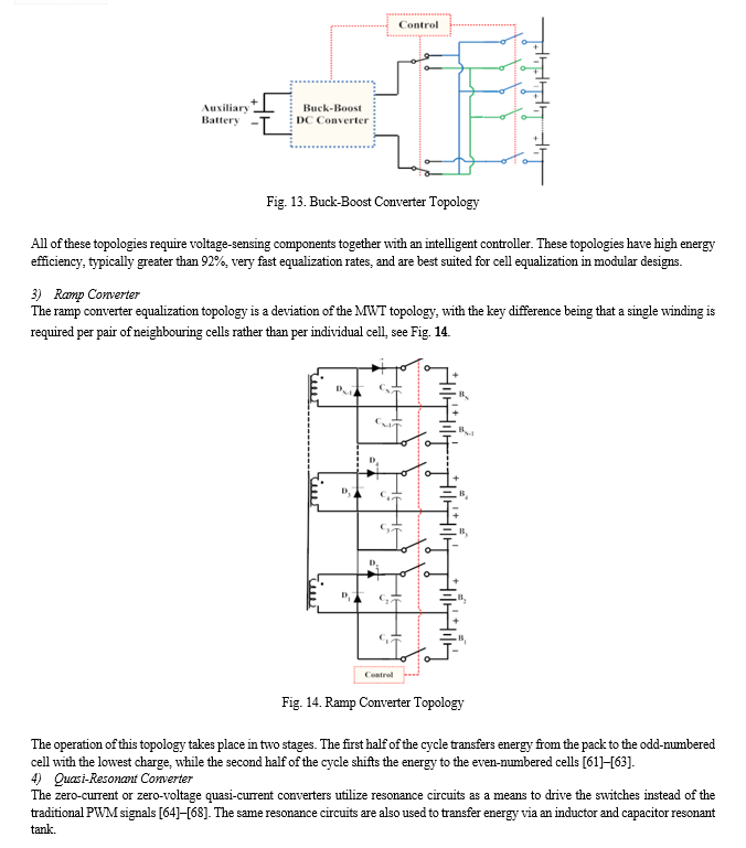
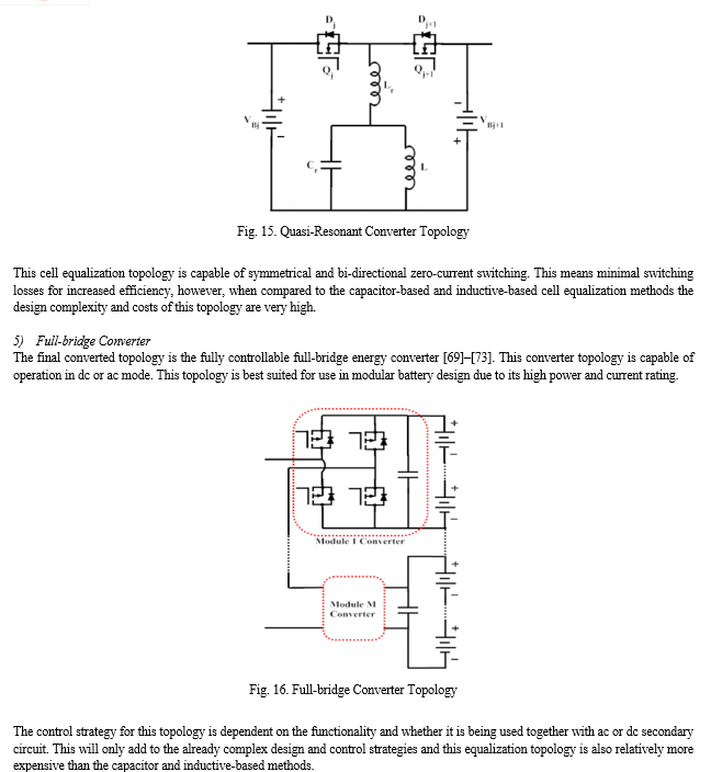
In recent times the idea to use basic electronic converters as a means to equalize the energy between the series-connected cells of a battery pack has been revisited. These electronic energy converters include; ?uk converters, Buck/Boost converters, Ramp converters, Quasi-Resonant converters, and Bridge converters. Each of these converters requires complex control strategies, which in turn makes these converters very bulky and very expensive. Most of these converter-based cell equalization topologies are therefore better suited for high-power applications where energy is transferred between high-current cells or between series-connected battery modules.
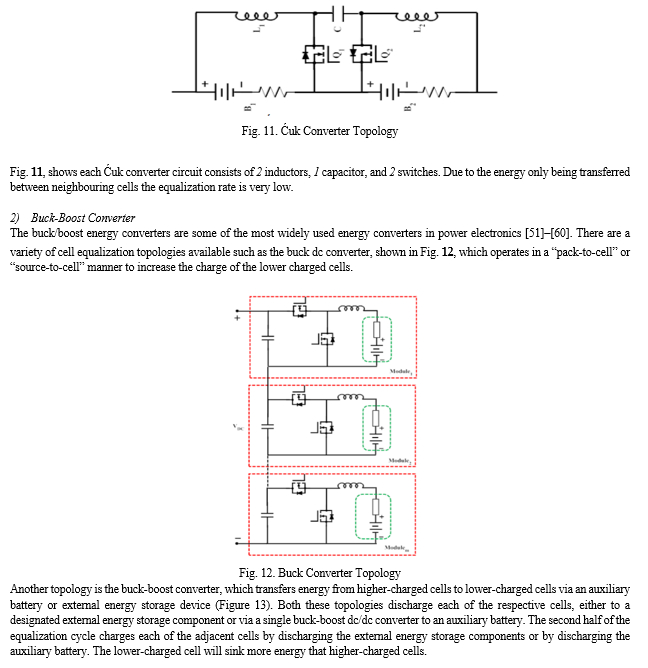
1) ?uk Converter
The ?uk converter is a bi-directional energy converter capable of equalizing the charge between two neighbouring cells [47]–[50]. Each circuit is only capable of transferring energy between two cells, thus n-1 circuits are required. This equalization technique also utilizes the alternating switch strategy, while utilizing the body diodes to discharge the external energy storage elements to the lower-charged cell.
III. RESULTS AND DISCUSSION
To do a comprehensive comparison of all the cell equalization topologies discussed in the previous section, Table 1 is a summary of the advantages and disadvantages of each of the cell equalization topologies and Table 2 introduces a score-based comparison of each of the topologies. In general, for low to medium-powered battery systems the switched resistor topology (passive equalization) is preferred due to the low cost, small size, and simplicity even though the equalization of cells through heat generation decreases the charging efficiency of the battery system. This topology is often preferred in normal electric vehicles for the same reasons. The capacitor-based equalization topologies are the best fit for low or medium-power applications where high energy efficiency is a top priority. In the case where faster equalization is a key factor the inductor-based topologies or the transformer-based topologies will be the top choice. For the higher-powered applications, the energy converter topologies are superior with the added benefit of full controllability. This is also true for modular energy storage systems, with size, cost, and complexity being the biggest drawbacks.
Table 2 refers to all the cell equalization techniques and additionally states the complexity of the control system required, the preferred modes of operation as well as the preferred power application. The control strategy has three levels, simple (can be implemented by hobbyists), medium (requires extensive electronic knowledge) and complex (requires validated engineering design). Low-power applications refer to battery capacity and are considered to be less than 15kWh, medium power ranges from 15kWh to 150kWh (below 1000V) and high-power applications alongside typical EV batteries are any batteries with a capacity greater than 150kWh. Operational modes refer to the battery system being in charging mode, discharging mode, or all modes which include standby mode where energy is flowing in or out of the battery. The equalization speed of the various topologies was measured relative to the approximate equalization rate which is measured in minutes per watt-hour. The efficiency of each of the equalization topologies was ranked according to estimated energy loss during the complete equalization cycle. The reaming criteria were structured in comparison to the preceding equalization topologies, thus the first equalization topology was placed in the center of a hierarchical comparison table. The second equalization topology was compared criteria-wise based on information obtained from academic references as shown in the previous section. Based on this the equalization method was ranked higher or lower per criteria. After this was repeated for all the equalization topologies, scores were assigned based on each equalization topology's rank and relevance to all other topologies.
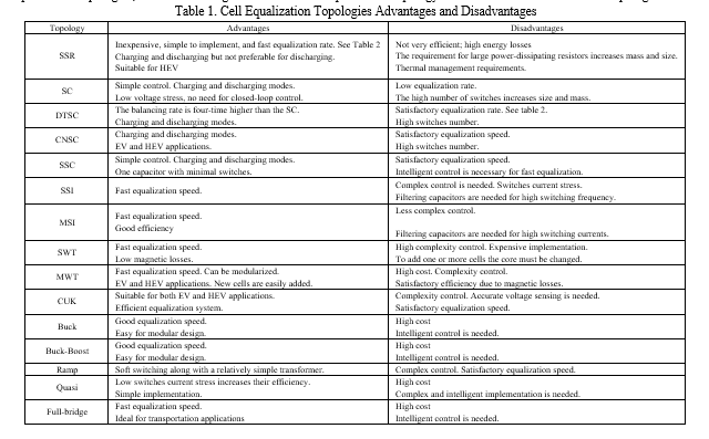
Table 2. Cell Equalization Topology Comparison
|
Name |
Speed |
Eff |
Control |
Size |
Cost |
Operate |
Power App |
Imp |
Stress |
Components n cells, m modules |
||||||||
|
|
min/Wh |
V |
I |
R |
L |
C |
SW |
D |
IC |
|||||||||
|
SSR |
3 |
10 |
2 |
Simple |
5 |
5 |
Charge mode |
Low - Medium |
5 |
2 |
2 |
N |
0 |
0 |
n |
0 |
0 |
|
|
SC |
2 |
90 |
5 |
Simple |
3 |
4 |
All modes |
Medium - High |
4 |
4 |
4 |
0 |
0 |
n-1 |
2n |
0 |
0 |
|
|
DTSC |
3 |
48 |
5 |
Simple |
3 |
3 |
All modes |
Medium - High |
4 |
4 |
4 |
0 |
0 |
n |
2n |
0 |
0 |
|
|
CNSC |
3 |
42 |
5 |
Simple |
3 |
3 |
All modes |
Medium - High |
4 |
4 |
4 |
0 |
0 |
n |
2n |
0 |
0 |
|
|
SSC |
3 |
42 |
5 |
Medium |
4 |
4 |
All modes |
Medium - High |
4 |
4 |
4 |
1 |
0 |
1 |
n+5 |
0 |
0 |
|
|
SSI |
4 |
7 |
4 |
Medium |
3 |
3 |
All modes |
Medium - High |
4 |
4 |
5 |
0 |
1 |
0 |
2n |
2n-2 |
0 |
|
|
MSI |
4 |
12 |
4 |
Medium |
3 |
2 |
All modes |
Medium - High |
4 |
4 |
5 |
0 |
n-1 |
0 |
2n-2 |
0 |
0 |
|
|
SWT |
4 |
7 |
3 |
Medium |
3 |
2 |
Charge mode |
Medium |
2 |
2 |
4 |
0 |
2 |
0 |
n+6 |
1 |
1 |
|
|
MWT |
4 |
12 |
3 |
Medium |
2 |
1 |
Charge mode |
Medium |
2 |
2 |
4 |
0 |
n+1 |
0 |
2 |
0 |
1 |
|
|
CUK |
3 |
2 |
4 |
Complex |
3 |
2 |
All modes |
Medium - High |
3 |
4 |
4 |
0 |
2n-2 |
n-1 |
2n-2 |
0 |
0 |
|
|
Buck |
5 |
0.9 |
5 |
Complex |
3 |
3 |
All modes |
Medium - High |
5 |
4 |
4 |
0 |
m |
m |
2m |
0 |
0 |
|
|
Buck Boost |
5 |
0.5 |
5 |
Complex |
3 |
2 |
All modes |
Medium - High |
5 |
4 |
4 |
0 |
1 |
1 |
n+7 |
0 |
0 |
|
|
Ramp |
3 |
3.5 |
3 |
Complex |
2 |
1 |
All modes |
Medium - High |
2 |
3 |
3 |
0 |
n/2 |
n |
n |
n |
1 |
|
|
Quasi |
3 |
0.7 |
4 |
Complex |
2 |
1 |
All modes |
High |
4 |
1 |
1 |
0 |
2n-2 |
n-1 |
2n-2 |
0 |
0 |
|
|
Full Bridge |
5 |
0.5 |
5 |
Complex |
2 |
2 |
All modes |
High |
3 |
2 |
2 |
0 |
0 |
m |
4m |
0 |
0 |
|
5 = Excellent, 4 = Very Good, 3 = Good, 2 = Satisfactory, 1 = Poor
V = Voltage, I = Current, R = Resistor, L = Inductor, C = Capacitor, SW = Switch, D = Diode, IC = Intelligence Circuit
Both Table 1 and Table 2 can be used as a guideline when choosing a suitable cell equalization topology to be added to the battery management system for a specialized battery application. Herewith follows a few examples of specialized applications and the best-suited cell equalization topologies found by making use of Table 1 and Table 2.
Solar Vehicle Challenges are international events where teams design and build solar-powered endurance racing electric vehicles. In some events, teams have to travel between 3000km and 5000km without charging the 5kWh battery from an external power source. This means that these lightweight vehicles require an ultra-efficient electrical system. The priorities for this low-power battery system are weight, size, and equalization efficiency. Referring to Table 1 and Table 2, most of the converter-based topologies as well as the transformer-based topologies can be eliminated due to the size and weight of the equalization systems. Resistor-based topologies can be eliminated due to the low equalization efficiency. The most suitable systems are the capacitor-based and the inductor-based cell equalization methods such as the double-tiered switched capacitor (DTSC) or the multi-switched inductor (MSI), because of the exceptional efficiency and high balancing rate when compared to component-based variations.
Grid-tied energy storage systems together with rooftop solar systems are being used throughout the commercial, industrial and domestic sectors as a means to minimize dependency on the electrical grid or load shifting for a more carbon-neutral electric infrastructure. The battery systems required can range from medium to high-powered applications and normally consist of multiple battery modules. The cell equalization priority is to increase the operational life of the battery system while implementation simplicity is also important. After consulting Table 1 and Table 2 the most suitable cell equalization topologies for this application are the buck-boost converter topology or the multi-winding transformer topologies.
One of the biggest revolutions in battery systems is the use of second-life batteries in emergency backup energy storage systems. Second-life batteries refer to battery cells that have been recycled from previously functional battery systems but have still been tested to have more than 70% useable battery capacity. These battery cells are assembled into extremely cost-effective battery systems, usually for use in large backup applications, with modules and cells of varying state of health (SoH) parameters. The equalization system required for this application must, first of all, operate during all operational states of the battery system. Thereafter priorities of the equalization system will be high power transfer between cells as well as a high equalization rate. Based on these criteria the most suitable cell equalization topology as deducted from tables 1 and 2 is the single or multi-winding transformer SWT/MWT) topology. The selection between these two topologies will be determined by the capacity of the application.
A new trending topic within the mining industry is the use of electrified vehicles, not only for use deep within the mines but more recently rubble removal vehicles. In this application mining vehicles are fitted with a relatively small all-electric hybrid energy storage (battery and supercapacitor), that will allow the empty vehicle to reach the top of the mining pile by discharging the battery. The now fully loaded vehicle will now travel downhill which will allow the electric motors to produce power that will be synced to both the supercapacitor bank and battery bank. This high-powered energy storage system requires very high equalization speed and high efficiency. Thus the only logical choice will be the full-bridge equalization topology. The workings of the full-bridge cell-to-pack topology will allow charging of the battery from the supercapacitor “auxiliary” bank.
For low-cost, low-powered applications such as electric wheelchairs and electric bicycles the switched shunt resistor (SSR) is the best solution as this topology is easiest to design and implement. Extremely cost-effective and reliable.
The key to choosing the best cell equalization topology is to prioritize or rank each of the attributes based on a specialized system and eliminate the topologies that do not meet the preferred requirements.
IV. DECLARATION OF COMPETING INTEREST
The authors declare that they have no known competing financial interests or personal relationships that could have appeared to influence the work reported in this paper.
V. ACKNOWLEDGEMENTS
This work was funded by the “Tshwane University of Technology (TUT) & the manufacturing, engineering and related services Sector Education and Training Authority (merSETA) Chair in Intelligent Manufacturing”.
Conclusion
The battery management system is a crucial part of the energy storage system and part of the BMS is the cell equalization unit. Cell equalization is a key subsystem as it contributes to battery system performance enhancements, while also extending battery life and ensuring battery safety. Numerous battery equalization techniques have been researched and presented by academics and application experts. There is no single equalization technique that fulfils all requirements, however, using the cell equalization technique best suited to a specific battery application can have numerous benefits. These benefits include extended battery life in emergency backup systems, cost reduction for small cost-sensitive energy storage systems such as e-bikes or implementation simplicity and cost reduction for large-scale production battery systems. Furthermore, the concepts discussed in this paper are also linked to real-world applications based on the characteristics of each cell equalization topology. The use of Table 1 and Table 2 can aid in the cell equalization selection, design, production, and implementation of a balanced battery system infrastructure. This paper presented a review of four equalization methods, resistor-based, capacitor-based, inductive-based and converter-based, each with its distinct topologies. The basic operation of each topology was explained followed by a comparative analysis together with the advantages and disadvantages of each topology. This paper can, therefore, not only be used for cell equalization selection but serve as a reference in identifying the potential of each cell equalization method to develop new and enhanced or hybrid topologies by focusing on overcoming the disadvantages and limitations of the topologies discussed.
References
[1] S. T. Hung, D. C. Hopkins, and C. R. Mosling, “Extension of battery life via charge equalization control,” IEEE Transactions on Industrial Electronics, vol. 40, no. 1, pp. 96–104, 1993. [2] N. H. Kutkut, H. L. Wiegman, D. M. Divan, and D. W. Novotny, “Design considerations for charge equalization of an electric vehicle battery system,” IEEE Transactions on Industry Applications, vol. 35, no. 1, pp. 28–35, 1999 [3] W. Bentley, “Cell balancing considerations for lithium-ion battery systems,” in The Twelfth Annual Battery Conference on Applications and Advances, 1997, pp. 223–226 [4] S. Moore and P. Schneider, “A review of cell equalization methods for lithium ion and lithium polymer battery systems,” SAE Publication, 2001 [5] M. J. Isaacson, R. P. Hollandsworth, P. J. Giampaoli, F. A. Linkowsky, A. Salim, and V. L. Teofilo, “Advanced lithium ion battery charger,” in Fifteenth Annual Battery Conference on Applications and Advances (Cat. No.00TH8490), 2000, pp. 193–198 [6] J. Cao, N. Schofield, and A. Emadi, “Battery balancing methods: A comprehensive review,” 2008 IEEE Vehicle Power and Propulsion Conference, pp. 1–6, 2008 [7] K. Zhi-Guo and Z. Chun-Bo, “Comparison and evaluation of charge equalization technique for series connected batteries,” \\ldots , 2006. PESC’06. 37th \\ldots, 2006 [8] G. Landrum and T. a. Stuart, “Fast equalization for large Lithium Ion batteries,” MTS/IEEE Oceans 2008 Conference and Exhibition, pp. 1–6, 2008 [9] M. Daowd, N. Omar, P. Van Den Bossche, and J. Van Mierlo, “Passive and active battery balancing comparison based on MATLAB simulation,” 2011 IEEE Vehicle Power and Propulsion Conference, pp. 1–7, 2011 [10] F. Porpora, U. Abronzini, C. Attaianese, M. Di Monaco, and G. Tomasso, “Real time balancing for modular passive battery management system,” in PCIM Europe 2019; International Exhibition and Conference for Power Electronics, Intelligent Motion, Renewable Energy and Energy Management, 2019, pp. 1–6 [11] X. Zhang, P. Liu, and D. Wang, “The Design and Implementation of Smart Battery Management System Balance Technology,” Journal of Convergence Information Technology, vol. 6, pp. 108–116, 2011 [12] S. Kivrak, T. Özer, and Y. O\\uguz, “Battery Management System Implementation with Pasive Control Method,” in 2018 IV International Conference on Information Technologies in Engineering Education (Inforino), 2018, pp. 1–4 [13] Y. Ye, K. W. E. Cheng, Y. C. Fong, X. Xue, and J. Lin, “Topology, Modeling, and Design of Switched-Capacitor-Based Cell Balancing Systems and Their Balancing Exploration,” IEEE Transactions on Power Electronics, vol. 32, no. 6, pp. 4444–4454, 2017 [14] A. F. Moghaddam and A. Van den Bossche, “A cell equalization method based on resonant switched capacitor balancing for lithium ion batteries,” in 2018 9th International Conference on Mechanical and Aerospace Engineering (ICMAE), 2018, pp. 37–341 [15] S. Goodarzi, R. Beiranvand, S. M. Mousavi, and M. Mohamadian, “A new algorithm for increasing balancing speed of switched-capacitor lithium-ion battery cell equalizers,” in The 6th Power Electronics, Drive Systems \\& Technologies Conference (PEDSTC2015), 2015, pp. 292–297 [16] X. Yang, L. Xi, Z. Gao, Y. Li, and J. Wen, “Analysis and Design of a Voltage Equalizer Based on Boost Full-Bridge Inverter and Symmetrical Voltage Multiplier for Series-Connected Batteries,” IEEE Transactions on Vehicular Technology, vol. 69, no. 4, pp. 3828–3840, 202 [17] C. G. Moral, D. F. Laborda, L. S. Alonso, J. M. Guerrero, D. Fernandez, C. Riva, and D. Reigosa, “Battery internal resistance estimation using a battery balancing system based on switched capacitors,” IEEE Transactions on Industry Applications, 2020 [18] Y. Ye and K. W. E. Cheng, “Modeling and analysis of series-parallel switched-capacitor voltage equalizer for battery/supercapacitor strings,” IEEE journal of emerging and selected topics in power electronics, vol. 3, no. 4, pp. 977–983, 2015. [19] Y. C. Fong, K. W. E. Cheng, S. R. Raman, and X. Wang, “Multi-Port Zero-Current Switching Switched-Capacitor Converters for Battery Management Applications,” Energies, vol. 11, no. 8, p. 1934, 2018. [20] C. Pascual and P. T. Krein, “Switched capacitor system for automatic series battery equalization,” in Proceedings of APEC 97 - Applied Power Electronics Conference, 1997, vol. 2, pp. 848–854 vol.2. [21] a. Baughman and M. Ferdowsi, “Double-Tiered Capacitive Shuttling Method for Balancing Series-Connected Batteries,” 2005 IEEE Vehicle Power and Propulsion Conference, pp. 50–54, 2005. [22] A. C. Baughman and M. Ferdowsi, “Double-tiered switched-capacitor battery charge equalization technique,” IEEE Transactions on Industrial Electronics, vol. 55, no. 6, pp. 2277–2285, 2008. [23] T. M. Bui, C.-H. Kim, K.-H. Kim, and S. B. Rhee, “A modular cell balancer based on multi-winding transformer and switched-capacitor circuits for a series-connected battery string in electric vehicles,” Applied Sciences, vol. 8, no. 8, p. 1278, 2018. [24] M. Daowd, M. Antoine, N. Omar, P. Lataire, P. Van Den Bossche, and J. Van Mierlo, “Battery management system—Balancing modularization based on a single switched capacitor and bi-directional DC/DC converter with the auxiliary battery,” Energies, vol. 7, no. 5, pp. 2897–2937, 2014. [25] C. Speltino, “Cell equalization in battery stacks through state of charge estimation polling,” \\ldots Control Conference (ACC \\ldots, 2010. [26] G. Noh and J.-I. Ha, “High Reliable Power Conversion System with Active Battery Balancing Capability,” in 2020 IEEE Applied Power Electronics Conference and Exposition (APEC), 2020, pp. 3358–3363. [27] M. Daowd, M. Antoine, N. Omar, P. van den Bossche, and J. van Mierlo, “Single Switched Capacitor Battery Balancing System Enhancements,” Energies, vol. 6, no. 4, pp. 2149–2174, 2013. [28] Y. Chen, X. Liu, H. K. Fathy, J. Zou, and S. Yang, “A graph-theoretic framework for analyzing the speeds and efficiencies of battery pack equalization circuits,” International Journal of Electrical Power \\& Energy Systems, vol. 98, pp. 85–99, 2018. [29] Z. Zhang, H. Gui, D.-J. Gu, Y. Yang, and X. Ren, “A hierarchical active balancing architecture for lithium-ion batteries,” IEEE Transactions on Power Electronics, vol. 32, no. 4, pp. 2757–2768, 2016 [30] S. Wang, S. Yang, and W. Yang, “A New Sort of Equalization Circuit Based on Coupled Inductors for Series-connected Battery Strings,” in 2019 22nd International Conference on Electrical Machines and Systems (ICEMS), 2019, pp. 1–6. [31] A. Farzan Moghaddam and A. Van den Bossche, “An efficient equalizing method for lithium-ion batteries based on coupled inductor balancing,” Electronics, vol. 8, no. 2, p. 136, 2019. [32] T. H. Phung, A. Collet, and J.-C. Crebier, “An optimized topology for next-to-next balancing of series-connected lithium-ion cells,” IEEE transactions on power electronics, vol. 29, no. 9, pp. 4603–4613, 2013. [33] C. S. Moo, Y. C. Hsieh, I. S. Tsai, and J. C. Cheng, “Dynamic charge equalisation for series-connected batteries,” IEE Proceedings - Electric Power Applications, vol. 150, no. 5, pp. 501–505, 2003. [34] R. K. Vardhan, T. Selvathai, R. Reginald, and P. Sivakumar, “Modelling of Multi Inductor-based Balancing of Battery Pack for Electrical Mobility,” Defence Science Journal, vol. 69, no. 3, pp. 266–273, 2019. [35] X. Wang, K. W. E. Cheng, and Y. C. Fong, “Non-equal voltage cell balancing for battery and super-capacitor source package management system using tapped inductor techniques,” Energies, vol. 11, no. 5, p. 1037, 2018. [36] T. H. Phung, J. C. Crebier, A. Chureau, A. Collet, and V. Nguyen, “Optimized structure for next-to-next balancing of series-connected lithium-ion cells,” in Applied Power Electronics Conference and Exposition (APEC), 2011 Twenty-Sixth Annual IEEE, 2011, pp. 1374–1381. [37] X. Tang, C. Zou, T. Wik, K. Yao, Y. Xia, Y. Wang, D. Yang, and F. Gao, “Run-to-run control for active balancing of lithium iron phosphate battery packs,” IEEE Transactions on Power Electronics, vol. 35, no. 2, pp. 1499–1512, 2019. [38] A. Pr?bstl, S. Park, S. Narayanaswamy, S. Steinhorst, and S. Chakraborty, “SOH-aware active cell balancing strategy for high power battery packs,” in 2018 Design, Automation \\& Test in Europe Conference \\& Exhibition (DATE), 2018, pp. 431–436. [39] A. M. Imtiaz, F. H. Khan, and H. Kamath, “A low-cost time shared cell balancing technique for future lithium-ion battery storage system featuring regenerative energy distribution,” in 2011 Twenty-Sixth Annual IEEE Applied Power Electronics Conference and Exposition (APEC), 2011, pp. 792–799. [40] H. Park, C. Kim, and C. Kim, “A modularized charge equalizer for an HEV lithium-ion battery string,” IEEE Transactions on Industrial Electronics, vol. 56, no. 5, pp. 1464–1476, 2009. [41] D. V. Cadar, D. M. Petreus, and T. M. Patarau, “An energy converter method for battery cell balancing,” in 33rd International Spring Seminar on Electronics Technology, ISSE 2010, 2010, pp. 290–293. [42] M. Einhorn, W. Roessler, and J. Fleig, “Improved performance of serially connected Li-ion batteries with active cell balancing in electric vehicles,” Vehicular Technology, IEEE \\ldots, vol. 60, no. 6, pp. 2448–2457, 2011. [43] C. C. Kim and H. Park, “Individual charge equalization converter with parallel primary winding of transformer for series connected lithium-ion battery strings in an HEV,” Journal of power \\ldots, vol. 9, no. 3, pp. 472–480, 2009. [44] W. Wang and M. Preindl, “Modeling and control of a dual cell link for battery-balancing auxiliary power modules,” in 2018 IEEE Applied Power Electronics Conference and Exposition (APEC), 2018, pp. 3340–3345. [45] S. Chakraborty, A. K. Jain, and N. Mohan, “Novel converter topology and algorithm for simultaneous charging and individual cell balancing of multiple Li-ion batteries,” in INTELEC 2004. 26th Annual International Telecommunications Energy Conference, 2004, pp. 248–253. [46] J. Shin, G. Seo, C. Chun, and B. Cho, “Selective flyback balancing circuit with improved balancing speed for series connected Lithium-ion batteries,” in The 2010 International Power Electronics Conference - ECCE ASIA -, 2010, pp. 1180–1184. [47] A. Farzan Moghaddam and A. Van den Bossche, “A ’cuk converter cell balancing technique by using coupled inductors for lithium-based batteries,” Energies, vol. 12, no. 15, p. 2881, 2019. [48] K. Nishijima, H. Sakamoto, and K. Harada, “A PWM controlled simple and high performance battery balancing system,” in 2000 IEEE 31st Annual Power Electronics Specialists Conference. Conference Proceedings (Cat. No. 00CH37018), 2000, vol. 1, pp. 517–520. [49] Y. Lee and C. Duh, “Battery equalization using bi-directional Cuk converter in DCVM operation,” \\ldots Conference, 2005. PESC’ \\ldots, pp. 765–771, 2005. [50] J. Yan, Z. Cheng, G. Xu, H. Qian, and Y. Xu, “Fuzzy control for battery equalization based on state of charge,” in 2010 IEEE 72nd Vehicular Technology Conference-Fall, 2010, pp. 1–7. [51] S. Park, T.-S. Kim, J.-S. Park, G.-W. Moon, and M.-J. Yoon, “A new battery equalizer based on buck-boost topology,” in 2007 7th Internatonal Conference on Power Electronics, 2007, pp. 962–965. [52] S. Wang, L. Kang, X. Guo, Z. Wang, and M. Liu, “A novel layered bidirectional equalizer based on a buck-boost converter for series-connected battery strings,” Energies, vol. 10, no. 7, p. 1011, 2017. [53] F. Peng, H. Wang, and L. Yu, “Analysis and design considerations of efficiency enhanced hierarchical battery equalizer based on bipolar CCM buck-boost units,” IEEE Transactions on Industry Applications, vol. 55, no. 4, pp. 4053–4063, 2019. [54] W. Hong, K.-S. Ng, J.-H. Hu, and C.-S. Moo, “Charge equalization of battery power modules in series,” in The 2010 International Power Electronics Conference-ECCE ASIA-. [55] W. Wang and M. Preindl, “Dual Cell Links for Battery-Balancing Auxiliary Power Modules: A Cost-Effective Increase of Accessible Pack Capacity,” IEEE Transactions on Industry Applications, vol. 56, no. 2, pp. 1752–1765, 2019. [56] V.-L. Pham, V.-T. Duong, and W. Choi, “High-efficiency active cell-to-cell balancing circuit for Lithium-Ion battery modules using LLC resonant converter,” Journal of Power Electronics, vol. 20, no. 4, pp. 1037–1046, 2020. [57] F. Baronti, G. Fantechi, R. Roncella, and R. Saletti, “High-efficiency digitally controlled charge equalizer for series-connected cells based on switching converter and super-capacitor,” IEEE Transactions on Industrial Informatics, vol. 9, no. 2, pp. 1139–1147, 2012. [58] A. Fares, C. Klumpner, and M. Sumner, “Investigating the benefits and limitations of cascaded converter topologies used in modular battery systems,” in 2017 IEEE 26th International Symposium on Industrial Electronics (ISIE), 2017, pp. 2123–2130. [59] X. Liu, Z. Gao, X. Huang, and Y. Zou, “Large equalization current control strategy for series connected battery packs based on buck-boost converter,” in 2018 International Power Electronics Conference (IPEC-Niigata 2018-ECCE Asia), 2018, pp. 3455–3459. [60] C. S. Moo, K. S. Ng, and Y. C. Hsieh, “Parallel Operation of Battery Power Modules,” 2005 International Conference on Power Electronics and Drives Systems, vol. 2, pp. 983–988, 2005. [61] T. Gottwald, Z. Ye, and T. Stuart, “Equalization of EV and HEV batteries with a ramp converter,” IEEE Transactions on Aerospace and Electronic Systems, vol. 33, no. 1, pp. 307–312, 1997. [62] A. Baughman and M. Ferdowsi, “Evaluation of the new sensorless approach in energy storage charge balancing,” in 2006 IEEE Vehicle Power and Propulsion Conference, 2006, pp. 1–5. [63] A. Farzan Moghaddam and A. Van den Bossche, “Forward Converter Current Fed Equalizer for Lithium Based Batteries in Ultralight Electrical Vehicles,” Electronics, vol. 8, no. 4, p. 408, 2019. [64] Y. Shang, C. Zhang, N. Cui, and J. M. Guerrero, “A cell-to-cell battery equalizer with zero-current switching and zero-voltage gap based on quasi-resonant LC converter and boost converter,” IEEE Transactions on Power Electronics, vol. 30, no. 7, pp. 3731–3747, 2014. [65] Y. Lee, C. Tsai, Y. Ko, and M. Cheng, “Charge equalization using quasi-resonant converters in battery string for medical power operated vehicle application,” in The 2010 International Power Electronics Conference - ECCE ASIA -, 2010, pp. 2722–2728. [66] G.-H. Min and J.-I. Ha, “Inner supply data transmission in quasi-resonant flyback converters for Li-ion battery applications using multiplexing mode,” IEEE Transactions on Power Electronics, vol. 34, no. 1, pp. 64–73, 2018. [67] J. Lu, Y. Wang, and X. Li, “Isolated bidirectional DC-DC converter with quasi-resonant zero-voltage switching for battery charge equalization,” IEEE Transactions on Power Electronics, vol. 34, no. 5, pp. 4388–4406, 2018. [68] Y.-. Lee and G.-. Cheng, “Quasi-Resonant Zero-Current-Switching Bidirectional Converter for Battery Equalization Applications,” IEEE Transactions on Power Electronics, vol. 21, no. 5, pp. 1213–1224, 2006. [69] S. Yarlagadda, T. T. Hartley, and I. Husain, “A battery management system using an active charge equalization technique based on a DC/DC converter topology,” IEEE Transactions on Industry Applications, vol. 49, no. 6, pp. 2720–2729, 2013. [70] M. Shousha, Z. Gong, A. Prodic, V. Marten, and J. Milios, “Assisting converter based integrated battery management system for automotive applications,” in Proceedings of PCIM Europe 2015; International Exhibition and Conference for Power Electronics, Intelligent Motion, Renewable Energy and Energy Management, 2015, pp. 1–8 [71] W. Wang and M. Preindl, “Design and implementation of a dual cell link for battery-balancing auxiliary power modules,” in 2018 IEEE Transportation Electrification Conference and Expo (ITEC), 2018, pp. 898–903. [72] M. Feizi and R. Beiranvand, “Simulation of a High Power Self-Equalized Battery Charger Using Voltage Multiplier and Phase-Shifted Full Bridge Converter for Lithium-Ion Batteries,” in 2020 11th Power Electronics, Drive Systems, and Technologies Conference (PEDSTC), 2020, pp. 1–6. [73] L. Maharjan, S. Inoue, H. Akagi, and J. Asakura, “State-of-Charge (SOC)-Balancing Control of a Battery Energy Storage System Based on a Cascade PWM Converter,” IEEE Transactions on Power Electronics, vol. 24, no. 6, pp. 1628–1636, 2009.
Copyright
Copyright © 2023 Raynard du Preeza, Christiaan Oosthuizenb, SJ Jacobs. This is an open access article distributed under the Creative Commons Attribution License, which permits unrestricted use, distribution, and reproduction in any medium, provided the original work is properly cited.

Download Paper
Paper Id : IJRASET48725
Publish Date : 2023-01-19
ISSN : 2321-9653
Publisher Name : IJRASET
DOI Link : Click Here
 Submit Paper Online

