Ijraset Journal For Research in Applied Science and Engineering Technology
- Home / Ijraset
- On This Page
- Abstract
- Introduction
- Conclusion
- References
- Copyright
Battery Monitoring and Protective System
Authors: Priyashree S, Murugesh H M, Deepika A B, Manjunath M, Shahapuram Bharath
DOI Link: https://doi.org/10.22214/ijraset.2024.62630
Certificate: View Certificate
Abstract
The growing demand for battery-powered devices and systems has led to an increased need for battery monitoring and protective systems. These systems play a critical role in ensuring the safe and reliable operation of battery-powered systems, such as electric vehicles, renewable energy systems, and mobile devices. This work emphasizes to monitor the state of charge (SOC) of the battery to ensure optimal performance and prevent premature failure. The battery is protected from damage due to overcharging, over-discharging, overheating, and short-circuiting. It also provides early warning of potential battery issues, such as low SOC or high temperature, so that corrective action can be taken to prevent damage. The charging and discharging of the battery is optimized to maximize its lifespan and efficiency. The proposed model facilitates remote monitoring and control of the battery using Arduino and BLYNK App accompanied by predictive maintenance and reduced downtime.
Introduction
I. INTRODUCTION
Batteries are one of the key components in our everyday lives. They are widely used as energy storage solutions in various applications, ranging from portable electronics to electric vehicles and renewable energy systems. They also help integrate renewable energy sources into the grid, and are becoming increasingly important in electric vehicle networks. Installing battery energy storage improves the use of renewable energy, offers a backup power source, less dependence on the grid, reduces carbon footprint, and offers long-term cost savings
Typically Industrial batteries are designed for performance, reliability and longevity. Different types of batteries offer different benefits and features that are taken into consideration when choosing a battery based on application. Lithium-ion Battery, Lead-acid Battery, and Nickel Cadmium Battery are very commonly used based on their affordability, weight, size and maintenance. The demand for batteries is expected to grow exponentially in the coming years.
However, batteries are prone to various issues, including voltage fluctuations, overcharging, overheating, and capacity degradation, which can lead to reduced performance, safety hazards, and even failure.
A battery monitoring system measures various battery parameters, such as temperature, voltage, current, and state of charge (SOC), in real-time to monitor the health and performance of the battery. This information is used to optimize the charging and discharging of the battery, extend its lifespan, and prevent damage due to overcharging, over-discharging, overheating, and short-circuiting [1], [2]. A battery protective system is designed to trigger protective mechanisms when the battery parameters exceed certain thresholds to prevent any further damage. It provides early warning of potential battery issues, such as low SOC or high temperature, so that corrective action can be taken to prevent any further damage.
Remote monitoring and control of the battery is another critical aspect of battery monitoring and protective systems. It enables predictive maintenance, reduces downtime, and allows the battery operator to monitor the battery's health and performance from a remote location.
Battery monitoring and protective systems play a crucial role in ensuring the safe and efficient operation of battery-powered devices and systems. Batteries are widely used as energy storage solutions in various applications, ranging from portable electronics to electric vehicles and renewable energy systems. However, batteries are prone to various issues, including voltage fluctuations, overcharging, overheating, and capacity degradation, which can lead to reduced performance, safety hazards, and even failure.
In this work, the battery monitoring and protective systems is designed to continuously monitor the vital parameters of batteries, such as voltage, current, temperature, and state of charge with the help of Arduino. This system makes use of sensors, control circuits, and intelligent algorithms to collect real-time data and analyze the battery's condition using the BLYNK app. Thus, based on the information obtained, appropriate actions are triggered to protect the battery and the associated equipment.
II. LITERATURE SURVEY
Maltezo [1] et.al, presents a battery management system for lead-acid battery banks used in E-vehicle. It is incorporated with a diagnostic, measurement, and monitoring system for improving Lead-acid battery performance based on efficiency and conservation.
It also includes determining the battery’s End-of-Life, parameters like no-load voltage, load voltage, mean current, maximum current, maximum temperature, depth of discharge, and Charge-Discharge cycle, that are measured at greater precision. Large battery consumption or Depth of Discharge occurs if the discharge current is lower. It showed in the result that the depth of discharge does not affect the battery life since the discharged current was low.
Shivanand Basgonda Patil [2], et.al., includes one important feature of a battery management system, that is to provide the user with the overall health of the battery pack and to monitor all other parameters of the battery pack like the voltage, current and temperature and other parameters. The main objective in this paper is the design and implementation of SoC and SoH for a lead-acid battery. In this work, an Arduino-based circuitry designed as a voltmeter, ohmmeter, ammeter, and thermometer is being used as measuring system. In the diagnostic system, the data from the SD card module, battery specifications and the measured parameters were all transferred to the database of the system. The monitoring system comprises a display of real time measured parameters, the critical parameter, the SOC and the estimation of the battery useful time by means of hours and minutes. The experimentation was carried out for State-of Health and Depth of Discharge using BattMan 3M1 and BattMan 3M2 device.
Nurul Fitriyah Roslan [3], et.al., focuses about Battery Monitoring System (BMoS), an electronic system that monitors rechargeable battery cells or packs with various parameters, such as battery voltage, current and State-of-Charge (SoC). This system is used to avoid overcharging or over- discharging of batteries to increase its shelf life. The mathematical equations are used in the programming code of the proposed system to interpret the value received by the Arduino Uno in decimal number from 10-bit ADC to the actual value measured by voltage and current sensor. The value of battery current is then used to calculate SoC of the battery. The developed prototype of BMoS is tested using 11.1 V Lithium-ion Battery and with DC motor used as a load to monitor the discharging process. The values of SoC and battery voltage as displayed on LCD are also being recorded.
Niraj Agarwal [4] et.al., details about an efficient energy-management system for Lead Acid Battery, using Matlab and Arduino, that is also developed and tested. The system uses an ACS712 sensor to detect current and voltage in the circuit while LM35 Thermistor is used to detect the temperature. The data output from these sensors is stored and manipulated through Arduino (microcontroller). The State of charge (SOC) of the battery is the index which shows the amount of charge present in the battery. This paper discusses about various methods used for determining the SOC of the battery. These include– Direct measurement, Book-keeping estimation, Adaptive systems and Hybrid method. In this work, Hybrid method is used, in which booking-keeping estimation method is implemented for finding the static SOC based on Open Circuit Voltage & temperature. The direct estimation method is used for determining the dynamic SOC based on charge flow. Thus the paper implies that the amount of charge in the battery varies significantly with the temperature, hence it is required to develop a better BMS that has a good understanding of the relation between the temperature and the SOC.
III. PROPOSED MODEL
A. bjective of Proposed Model
The main objective of the proposed battery monitoring and protective system includes the following aspects:
- Monitor battery health: A battery monitoring system aims to track the health and performance of the battery in real-time. It measures various battery parameters such as temperature, voltage, current, and state of charge (SOC) to ensure that the battery is operating within safe and optimal conditions [5], [6].
- Prevent damage: A battery protective system is designed to protect the battery from damage due to various factors such as overcharging, over-discharging, overheating, and short-circuiting. It triggers protective mechanisms when the battery parameters exceed certain thresholds to prevent any further damage.
- Optimize battery performance: A battery monitoring system aims to optimize the charging and discharging of the battery to maximize its lifespan and efficiency. It ensures that the battery is charged only when necessary and discharges only when needed [5], [6].
- Early warning: A battery monitoring system provides early warning of potential battery issues, such as low SOC or high temperature, so that corrective action can be taken to prevent any further damage.
- Facilitate remote monitoring and control: A battery monitoring system enables remote monitoring and control of the battery. It facilitates predictive maintenance and reduces downtime by allowing the battery operator to monitor the battery's health and performance from a remote location [7], [8].
Overall, the objectives of a battery monitoring and protective system are to ensure the safe and reliable operation of battery-powered systems, extend the lifespan and efficiency of the battery and minimize the risk of failure.
B. Hardware Requirements
The block diagram of Proposed Battery Monitoring and Protection System is as shown in Fig. 1. The major components that facilitate the Battery Monitoring and Protective System are as discussed below:
The temperature, current and voltage sensors are used to measure the significant parameters of the battery. The battery is connected in series with the sensors, these sensors are in turn connected in parallel with the data acquisition and battery monitoring system (LED display, Arduino, etc). The sensors are used to measure the current and voltage of the battery, and send values to the Arduino Uno for processing. Based on the instructions set, the calculated SoC is displayed on the LCD. The discharging process occurs when the battery supplies current to the DC motor, while the charging process occurs when the battery is connected to the charger.
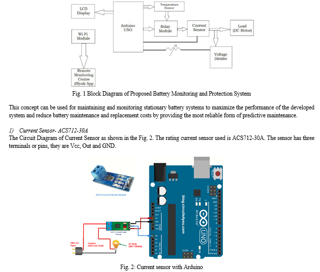
The 30A range Current Sensor Module ACS712 consists of a precise, low-offset, linear Hall circuit with a copper conduction path located near the surface of the die. Applied current flowing through this copper conduction path generates a magnetic field in which the Hall IC converts into a proportional voltage. The concept of sensing and controlling current flow is a fundamental requirement in a wide variety of applications including, over-current protection circuits, battery chargers, switching mode power supplies, digital watt meters, programmable current sources, etc.
The Vcc pin of the sensor is connected to the 5v pin of the Arduino that is used as the supply, Out pin of the sensor is the connected to the A0 pin of the Arduino and GND pin of the sensor is connected to the GND pin of the Arduino.
The output is observed on the serial monitor of the Arduino software using laptop. It can accurately detect AC or DC current. The maximum AC or DC that can be detected can reach 30A, and the present current signal can be read via analog I / O port of Arduino. It Provides isolation from the load and easy to integrate with any microcontroller unit where the outputs are analog voltage.
2) Voltage Sensor - ACS712:
The Circuit Diagram of Voltage Sensor is as shown in the Fig. 3. The ACS712 is a fully integrated, hall effect-based linear current sensor with 2.1kVRMS voltage isolation and an integrated low-resistance current conductor. Technically it is a current sensor that uses its conductor to calculate and measure the amount of current applied. The device accuracy is optimized through the close proximity of the magnetic signal to the Hall transducer. It is being used as a voltage sensor for measuring Open Circuit Voltage.
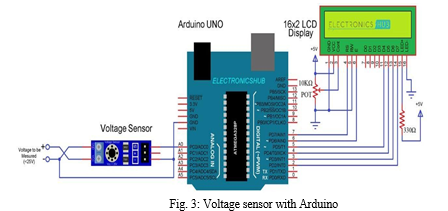
The sensor has three terminals or pins, they are Vcc, Out and GND. The Vcc pin of the sensor is connected to the 5v pin of the Arduino which is used as the supply. The Out pin of the sensor is the connected to the A0 pin of the Arduino and GND pin of the sensor is connected to the GND pin of the Arduino. The output is observed on the serial monitor of the arduino software with the laptop.
The commonly available Voltage Sensor Modules are nothing but just a voltage divider circuit. These are rated for 0 to 25V with 30 kilo-ohm and 7.5 kilo-ohm resistors. The voltage divider circuit which consists of 2 resistors connected in series. One end of this series connection is connected to the voltage to be measured (Vm) and the other end to the ground terminal. A voltage (V1) proportional to the measured voltage will appear at the junction of two resistors. This junction can then be connected to the analog pin of the Arduino. The voltage can be found out using the Eq.(3):

3) Temperature Sensor (LM35):
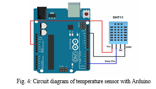
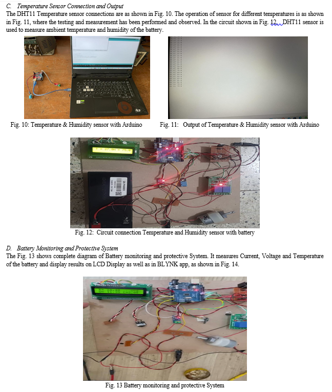
The connections of temperature and humidity sensor (LM35) are made as shown in the Circuit diagram, Fig. 4. The sensor comes with a dedicated NTC to measure temperature and an 8-bit microcontroller to output the values of temperature and humidity as serial data. The sensor is also factory calibrated and hence easy to interface with other microcontrollers.
The temperature sensor, LM35 is used for sensing the ambient temperature of the battery. This sensor has three pins or terminals, Vcc, GND and Data pin. The Vcc pin of the sensor is connected to the 5V pin of the Arduino which is used as the supply. The Data pin of the sensor is connected to the pin No 2 of the Arduino which is used as the data pin. The GND terminal of the sensor is connected to the GND pin on the Arduino. The output is observed on the serial monitor of Arduino software on laptop.
IV. IMPLEMENTATION
The current, voltage and temperature sensors are tested and appropriate outputs have been observed where the Arduino programming for the working of the sensors were carried out and calibration of sensors were also done during the process. The circuit diagram of temperature sensor with Arduino is as shown in Fig. 4.
A. Algorithm for current sensor:
- Initialize the sensor input pin as A0 and define the voltage per Amp constant.
- Start a serial communication at 9600 baud rate in the setup function.
- Initialize variables for voltage, RMS voltage, and RMS current.
- In the loop function, get the voltage peak-to-peak value using the get VPP() function.
- Calculate the RMS voltage using the peak-to-peak voltage and the root 2 constant.
- Calculate the RMS current using the RMS voltage and the voltage per Amp constant.
- Display the RMS value of current in Amps on the serial monitor.
B. Algorithm for Voltage sensor:
- Initialize the sensor input pin as A0 and define the voltage per Amp constant.
- Start a serial communication at 9600 baud rate in the setup function.
- Initialize variables for peak-to-peak voltage, RMS voltage, and RMS current.
- In the loop function, get the voltage peak-to-peak value using the get VPP() function.
- Calculate the RMS voltage using the peak-to-peak voltage and the root 2 constant.
- Display the RMS voltage in Volts on the serial monitor.
C. Algorithm for Temperature & Humidity sensor
- Include the Simple DHT library and define the pin number for the DHT11 sensor.
- In the setup function, start serial communication and print the header “Temperature and Humidity Data.”
- In the loop function, read the temperature and humidity data from the DHT11 sensor using the read function from the Simple DHT library.
- If the read is successful, print the temperature and humidity data in Celsius and percentage, respectively.
- Wait for 1.5 seconds before repeating the measurement.
V. RESULT AND DISCUSSION
A. Current Sensor Connection and Output
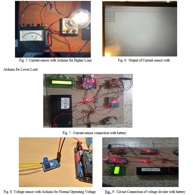
The working of current sensor connection for the set up is verified with and without lamp load is as shown in Fig. 5. In this circuit ACS712 current sensor is used for the current measuring purpose.. The output of current sensor for No Load, Higher load and Lower load conditions are displayed by the Arduino serial output is as shown in Fig. 6.
The current sensor connection with battery is as shown in Fig. 7. VCC is connected to the 5V pin on the Arduino board, GND is connected to the GND pin on the Arduino, and OUT is connected to the A0 pin on the Arduino. The other two Terminals are taken as the current in and current out (or) as power supply + & -.
B. Voltage Sensor Connection and Output
The ACS712 Voltage sensor connections are as shown in Fig. 8, is connected to measure the normal operating voltage of the set up. In the circuit shown in Fig. 9, the voltage divider is used for the voltage measuring purpose. As discussed in the Voltage sensor algorithm, the set up is designed for display of voltage as measured by the sensor. When the battery falls below the certain voltage the relay turns ON and the circuit will be cut off. This also aids to identify the amount of energy remaining in the battery. Thereby the State of Charge (SoC) can help to predict when a battery may need to be replaced or serviced. Thus prevent unexpected downtime or system failures.
To Begin the serial communication at a baud rate of 115200, start the BLYNK connection and set up the LCD display that will print initial messages. Include a Delay for 4 seconds, then clear the LCD display. The loop function is executed with the following procedure:
- Run the BLYNK.run() function to maintain the BLYNK connection.
- Call the vtgsensor function to read the voltage sensor values and update the LCD and BLYNK virtual pin.
- Call the current function to calculate the current values and update the LCD and BLYNK virtual pin.
- Call the battemp function to read the temperature sensor values and update the LCD and BLYNK virtual pin.
- Call the battemp1 function to read the additional temperature sensor values and update the BLYNK virtual pin.
- Call the potentiometer function to read the potentiometer values, update the LCD and BLYNK virtual pin, and control relay1 based on certain conditions.
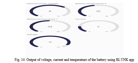
The BLYNK app will Read the current, voltage and temperature sensor values and update on the LCD display instantaneously. A suitable potentiometer is used to Control relays based on the operating conditions of the system. Thus the battery monitoring systems can detect anomalies, trigger safety measures, and provide essential information for optimizing battery performance, extending battery life, and ensuring safe battery operation.
Conclusion
The proposed battery monitoring system includes temperature sensor, current sensor and voltage divider which sense the temperature, current and voltage of the battery or load with the help of Arduino. With proper coding the working of sensors, load, battery and relay has been observed effectively. During the initial stage, the analysis is carried out using an AC lamp load, while the actual monitoring and protection was carried out with Lithium Ion Battery. In the final phase, the real time measurement was carried out with battery for the three significant parameters voltage, current & temperature. The process also includes cutting off the circuit when the voltage exceeds the pre-set value. In the proposed system, the BLYNK app is used to observe the measurements of voltage, current and temperature of the battery. Thus, the battery monitoring systems integrated into portable electronic devices can provide protection against overcharging, over-discharging, and short circuits. This model can also be enhanced to indicate the amount of energy remaining in the battery, ie., the State of Charge helps to optimize the battery life by preventing overcharging or over-discharging. Overcharging or over-discharging can lead to reduced battery life or even permanent damage to the battery. They also ensure safe battery usage and reduce the risk of accidents, such as battery-related burns or device malfunctions. It also facilitates remote monitoring and control of the battery to enable predictive maintenance and reduce downtime of the battery.
References
[1] Maltezo, M. R. C., Thio-Ac, A. C., Castillo, A. M. C., Gattu, L. E., Hernandez, C. E. A., Labuan, J. J. C., Navales, L. F., Sopeña, E. C., Arago, N. M., Galido, E. A., Madrigal, G. A. M., Pascion, C. G., & Tolentino, L. K. S. (2021), ‘Arduino-based battery monitoring system with state of charge and remaining useful time estimation’, International Journal of Advanced Technology and Engineering Exploration, 8(76), March 2021. [2] Shivanand Basgonda Patil, Akshay Sanjay Kamme, Aniket Sunil Patil, Vaibhav Ravso Patil, Apurva A Londhe,, ‘Design of Battery Health Monitoring System Using Arduino Uno’, International Journal of Advanced Research in Electrical, Electronics and Instrumentation Engineering (IJAREEIE)| e-ISSN: 2278 – 8875, p-ISSN: 2320 – 3765| www.ijareeie.com | Impact Factor: 7.122, Volume 9, Issue 6, June 2020. [3] Nurul Fitriyah Roslan and Wan Mariam Wan Muda, ‘Development Of Battery Monitoring System Using Arduino Uno Microcontroller’, University Malaysia Terengganu Journal of Undergraduate Research, Volume 2 Number 4,October 2020: 41-50, eISSN: 2637-1138. [4] Niraj Agarwal, Phulchand Saraswati, Ashish Malik, Yogesh Krishan Bhateshvar, ‘Design a Battery Monitoring System for Lead-Acid Battery’, International Conference Proceeding ICCCT Dec 2017, ISSN: 2320-2882, International Conference On Communication & Computational Technologies by RIET, Jaipur & IJCRT.ORG 2017. [5] Jun Lee, Xiaosong Hu, Xueliang Huang, Shulong Zhou, \"A Review of Battery Monitoring and Management Systems for Electric Vehicle Applications\", Published in Energies, 2017. [6] Omar Hegazy, Fatma Ashour, Noha A. El-Zaher, \"Battery Management Systems in Electric and Hybrid Vehicles: A Review\" Journal of Power Sources, 2015 [7] Z. Yang, D. Xiong, X. Hu, Z. Guo, L. Zheng, \"Battery Monitoring System Based on Wireless Sensor Networks for Electric Vehicles\" IEEE Transactions on Industrial Informatics, 2014 [8] Weiming Wang, Xiaoqiang Guo, Kezhao Pang,, \"Battery Management Systems in Electric Vehicle \", IEEE Transactions on Vehicular Technology, 2018.
Copyright
Copyright © 2024 Priyashree S, Murugesh H M, Deepika A B, Manjunath M, Shahapuram Bharath. This is an open access article distributed under the Creative Commons Attribution License, which permits unrestricted use, distribution, and reproduction in any medium, provided the original work is properly cited.

Download Paper
Paper Id : IJRASET62630
Publish Date : 2024-05-24
ISSN : 2321-9653
Publisher Name : IJRASET
DOI Link : Click Here
 Submit Paper Online

