Ijraset Journal For Research in Applied Science and Engineering Technology
- Home / Ijraset
- On This Page
- Abstract
- Introduction
- Conclusion
- References
- Copyright
Analytical Study on Behaviour of Different Shapes in Voided Slabs and Voided Beams
Authors: Srivani. M, D. K. Ramadevi
DOI Link: https://doi.org/10.22214/ijraset.2024.65181
Certificate: View Certificate
Abstract
Slab is largest member which consumes concrete and when load acting on the slab is large or clear span between columns is more, the slab thickness is increasing. It leads to consume more material such as concrete and steel due to that, self-weight of slab is increased. To avoid these disadvantages various studies are carried out and researchers suggest voided slab system [1]. To reduce the concrete in center of the slab by using hollow recycled plastic balls. High density polyethylene (HDPE) hollow balls replace the ineffective concrete in the center of the slab, thus decreasing the dead weight and increasing the efficiency of the floor. The advantages are less energy consumption both in production, transport and carrying out, less emission exhaust gases from production and transport, especially CO2 [2]. The aim of this paper is to discuss about the comparison of conventional slab and voided slab and also conventional beam and voided beam by using ANSYS software.
Introduction
I. INTRODUCTION
Concrete has been used for many years and has played a chief role in creating vast infrastructure as well as residential projects. Voided beams are R.C.C beams which decrease the amount of concrete with the help of voids. Hollow core slab, also known as a voided slab. They are pre stressed concrete elements that have a constant cross section. In buildings, slab is one of the important structural member as well as the largest member consuming concrete. Therefore by using high density polyethylene balls the consumption of concrete can be optimized. Void forms in the middle of a slab eliminates 35% of a slabs self-weight removing constraints of high dead loads and short spans. Hollow cores are manufactured using high tensile strength pre stressed strands or single wire which are embedded within the element. Bubble deck eliminates up to 35% of the structural concrete when coupled with the reduced ground thickness and facade, smaller foundations and columns, construction fees may be reduced by as lots as 10%.On most tasks this technique gets rid of over 95% of highly-priced formwork as compared with conventional concrete structures. Regardless of project size, shape or complexity; simply shore, area, and pour to quickly deploy concrete decks. Off-site manufacturing, fewer vehicle trips and crane lifts in addition to simple installation all integrate to limit working risks, in addition to decrease health & safety risks.
The objectives of this project are,
- To study the effects of voided beams and voided slabs and their properties.
- To simulate the behaviour of voided beams and voided slabs in different shapes using ANSYS.
- Reduced concrete usage – 1 Kg recycled plastic replaces 100 Kg of concrete.
- Environmentally Green and Sustainable – reduced energy & carbon emission.
II. LITERATURE REVIEW
- Slab is largest member which consumes concrete and when load acting on the slab is large or clear span between columns is more, the slab thickness is increasing. It leads to consume more material such as concrete and steel due to that, self-weight of slab is increased. To avoid these disadvantages various studies are carried out and researchers suggest voided slab system. In this study the design process for plastic voided slab is compared with reinforced concrete solid flat slab through a design comparison of typical bays of 4.54 m by 4.54 m (15 feet by 15 feet), 6.05 m by 6.05 m (20 feet by 20 feet), 7.57 m by 7.57 m (25 feet by 25 feet) and 9.08 m by 9.08 m (30 feet by 30 feet) with the same thickness of 0.25 m (10 inch). The solid flat slab design process follows the provisions made in the ACI 318-11 and the plastic voided slab design process is modified from the Bubble Deck Design Guide for compliance with BCA using AS3600 and Euro code 2. Also, the finite element analysis of the slab panels has been carried out by using ANSYS Workbench 14.5 to find out the deformation. The obtained results of deformation should be checked for live load and long-term deformation as per ACI 318-11.
- Concrete plays a major role in the construction field. In building construction slab is one of the largest and important structural member consuming concrete. Concrete slab use more concrete than requirement, hence has to be optimized. So reduce the concrete in center of the slab by using hollow recycled plastic balls. High density polyethylene (HDPE) hollow balls replace the ineffective concrete in the center of the slab, thus decreasing the dead weight and increasing the efficiency of the floor. Voids in the middle of a flat slab eliminate 35% of a slab’s self-weight removing constraints of high dead loads and short spans. Combination of recycled plastic bubbles permits 50% longer spans between columns without any beams. This provides a wide range of cost and construction benefits. In this paper, Finite element analysis (FEA) was carried out by using ANSYS software to study the structural behavior of bubble deck slab with different arrangements of elliptical balls.
- Bubble deck slab is a method of virtually eliminating all concrete from the middle of a floor slab, which is not performing any structural function, thereby dramatically reducing structural dead weight. High density polyethylene hollow spheres replace the in-effective concrete in the centre of the slab, thus decreasing the dead weight and increasing the efficiency of the floor. By introducing the gaps leads to a 30 To 50% lighter slab which reduces the loads on the columns, walls and foundations, and of course of the entire building. The advantages are less energy consumption - both in production, transport and carrying out, less emission - exhaust gases from production and transport, especially CO2 .The aim of this paper is to discuss about various properties of Bubble deck slab based on the various studies done abroad. Moment, deflection and stress distributions are verified using Finite Element Method (FEM) in SAP2000.
- A structural system of Tremendous importance in constructions are slabs or floor systems, it is called two dimensional slab structural elements, where the third dimension is small compared with the other two basic dimensions. Loads acting perpendicular slabs, to the flat principal, may be from different shapes Y configurations relying on the need for which apply at all times seeks to make them lighter but covering the greatest possible distances and always seeking to improve productivity and energy savings in construction. These systems reduce or change the concrete within the middle of the slab by a lighter material to from reduce the weight own from the structure. But nevertheless these relieved as in slabs reduce the strength thereof before exposure to shear forces and fire. BD is a biaxial technology that will increase span lengths and makes floors thinner by means of lowering the weight at the same time as keeping the performance of reinforced concrete slabs. This paper gives some of the reviews related to bubble Deck slab.
- In buildings, slab is one of the important structural member as well as the largest member consuming concrete. Therefore by using high density polyethylene balls the consumption of concrete can be optimized. The main aim is to study the practicality of hollow plastic balls in a reinforced concrete slab. The slab specimen casted were of three types namely, conventional slab, B.D.S of 50 mm diameter and B.D.S of 100 mm diameter having dimensions of 750 mm X 500 mm X 150 mm. The testing of slab specimen was done on universal testing machine by giving one point line loading. Finite element analysis on slab specimen is also done by using ANSYS WORKBENCH 16.0. From the results it can be concluded that Bubble deck slab of 50 mm and 100 mm diameter can be used in practice, as the deflection values of the particular slabs are within the permissible limit as stated in IS Code.
- The objective of this study is to perform the behavioral analysis of conventional slab and bubble deck slab using ansys workbench 14.0. This comparative study includes the study of normal slab and slab with HDPE spherical ball at center to form voids. High Density polyethylene (HDPE) empty sphere replaces the ineffective concrete at neutral axis of the slab section, in this way diminishing the dead weight. Simply supported End conditions are assumed for both slabs under Static (udl) loads. The analysis result showed the total deflection , Von-mises Stress of both slab under uniformaly distributed load for different end conditions. This paper moreover displays a review on the properties and preferences of Bubble Deck section over conventional slab.
- Biaxial voided slab is an emerging slab system which reduces its self-weight up to 50% in comparison with the conventional reinforced concrete solid slab. It reduces both one-way and two-way (punching) shear capacity about 40%. Therefore, an effective way of predicting the punching shear capacity is investigated as the presence of voids alters the critical failure section. In addition, eight full-scale specimens were tested with the sphere and cuboid shape of voids. Finally, experimental results of present study and test data collected from literature (33 specimens) were compared with predictions by the relevant code provisions. Hence, the presence of voids is considered by modifying the critical section depending on the void location. Further, only the effective concrete area is considered to predict the punching shear capacity. After the modifications, the predictions by all three building standards lead to satisfactory results.
- Voided slab is used in the construction of floor slabs, roof slabs and short, medium span slab bridges. Voids of circular shape are simpler for construction and the stress concentration around these voids is less critical than any other shape. The presented study is concerned with the experimentation general deformational behavior of the reinforced concrete voided slab under unsymmetrical case of loading. The voided reinforced concrete slab of dimensions 1.8 m x 1.04 m x 0.12 m having void diameters of 50 mm was modelLed and tested under eccentric loading. The slab was tested as simply supported on span of 1.60 m. The main focus of proposed work on comparative study of experimentation on voided slab using ANSYS Workbench 14.5.
- Slab is largest member which consumes concrete. If the load acting on the slab is large or clear span between columns is more, the thickness of slab increases. It leads to consume more material such as concrete and steel due to this, self-weight of slab is avoid these disadvantages voided slab system is used. Reinforced concrete slab with plastic voids is a new and innovative type of construction. High density polyethylene (HDPE) hollow spheres replace the ineffective concrete from the centre of the slab and decrease the dead load. The advantages are less energy consumption both in production and transport, less emission of exhaust gases from production and transport, especially CO2and reduce the material, the load, lower the cost and it is also a Green Technology. The effect is to decrease the overall weight by as much as 15% when compared to a solid slab of the same bearing capacity.
- In recent modern buildings, voided slabs have been extensively employed because of the high reduction in their self-weight up to 35%. Five half-scale specimens were fabricated. They contained 96 spherical voids distributed uniformly throughout the slab area, three of them were strengthened by six embedded steel sheets, three sheets in each direction. The sheets were orthogonally configured and intersected below the column stub. The variable of the study was the sheet thickness (0.8?mm, 1.0?mm, and 1.2?mm). The specimens were subjected to a gradually concentrated load through the column up to collapse. The test results revealed that significant losses were recorded in the strength, stiffness, ductility, and energy absorption of the voided slab without sheets compared with the reference one.
III. FORMULATION
Deflection due to Live Load
(ACI 318-11 Table 9.5 b) ?L.L = ?u max X L.L / (1.2 D.L + 1.6 L.L) ‹ (L/360) Long-term Deflection:
(ACI 318-11 9.5.2.5) ? (3D.L+ L.L) = ?u max X (3D.L+ L.L)/ (1.2 D.L + 1.6 L.L) ‹ (L/180)
A. Benefits of BDS
According to representatives of technology in Brazil, many benefits can be cited for BDT, such as:
- Elimination of beams - formwork economy, cheaper and faster execution of masonry and facilities.
- Reducing the volume of concrete - 3.5 kg of recyclable plastic balls 14,31kg replace concrete.
- Carbon energy and emission reduction - because of the utilisation of reusable plastic, reducing the consumption of raw materials.
- Freedom in the projects - versatile layouts that adapt easily to curvilineal and irregular layouts.
- Increasing gaps in either direction - slab affiliation on to the pillars with no beam through concrete in-situ.
- Reduced own weight - 35% smaller, allowing reduction in the foundations.
- Increased interior pillar - up to 50% more than traditional structures.
IV. ANALYSIS
|
S.NO |
Name of material |
Property |
Value |
|
1. |
Steel |
Modulus of Elasticity (E) |
200000 MPa |
|
Density (ρ) |
7850 kg/m3 |
||
|
Poisson’s Ratio(µ) |
0.3 |
||
|
2. |
Concrete |
Modulus of Elasticity (E) |
22361MPa |
|
Density (ρ) |
2308 kg/m3 |
||
|
Poisson’s Ratio(µ) |
0.18 |
||
|
3. |
HDPE balls |
Modulus of Elasticity (E) |
1035 MPa |
|
Density (ρ) |
970 kg/m3 |
||
|
Poisson’s Ratio(µ) |
0.4 |
Table 1 Material properties
Fig 1 Reinforcement detail given for conventional slab

Fig 2 Four side fixed support given in slab
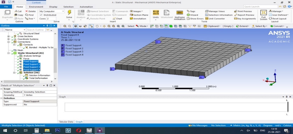
Fig 3 load given for conventional slab
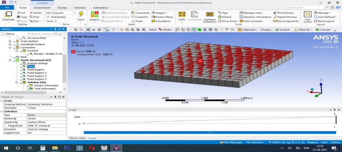
Fig 4 Total deformation
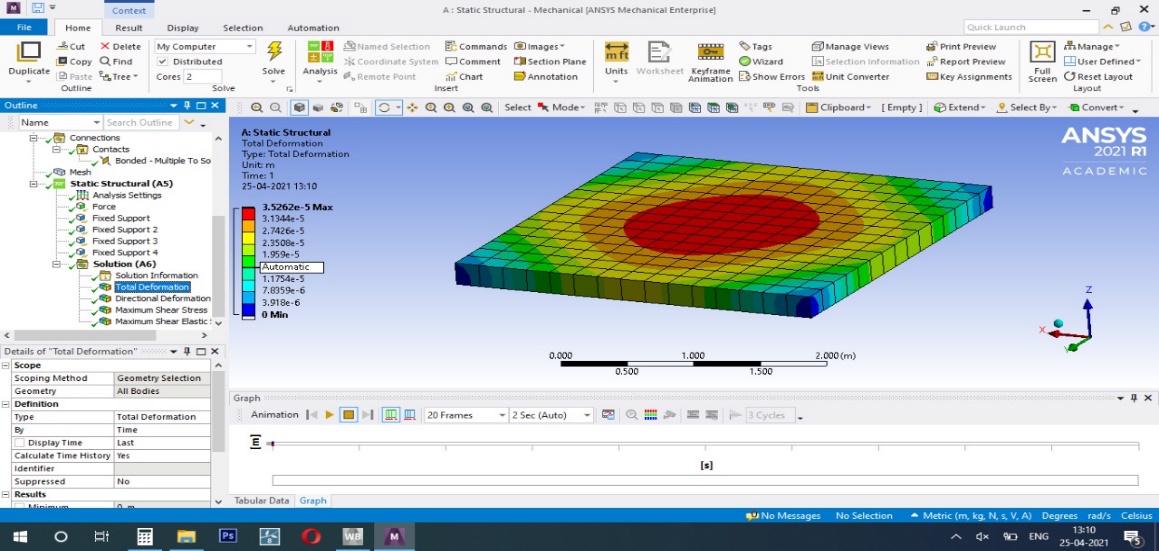
Fig 5 Directional deformation in slab
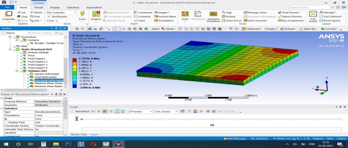
Fig 6 Reinforcement given for voided slab
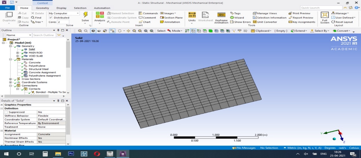
Fig 7 Four side fixed support given for voided slab
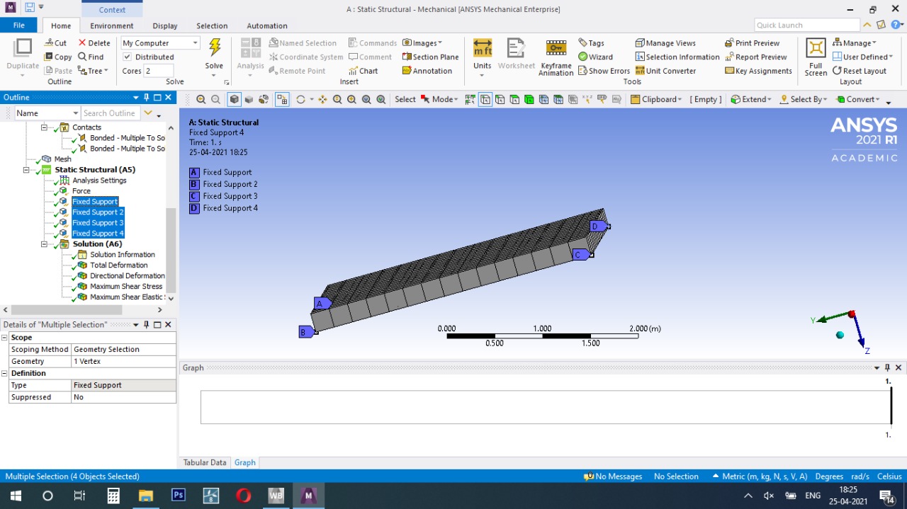
Fig 8 Load given for voided slab
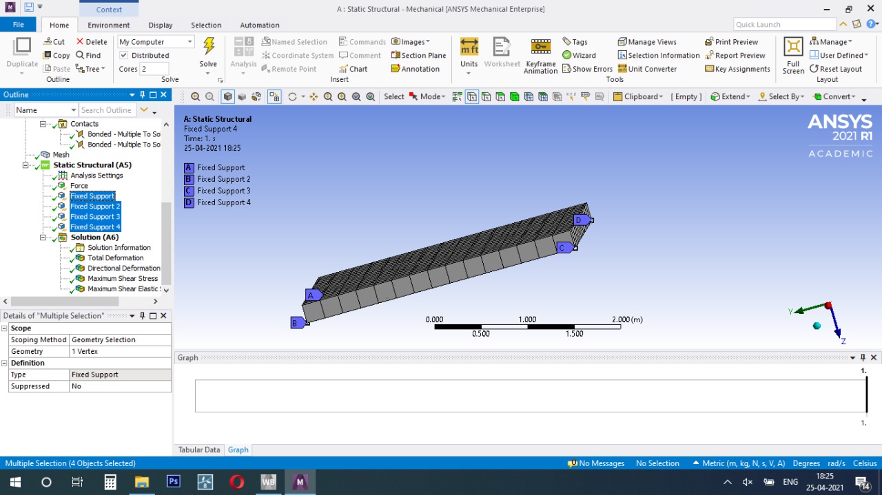
Fig 9 Voids arrangement in main rod
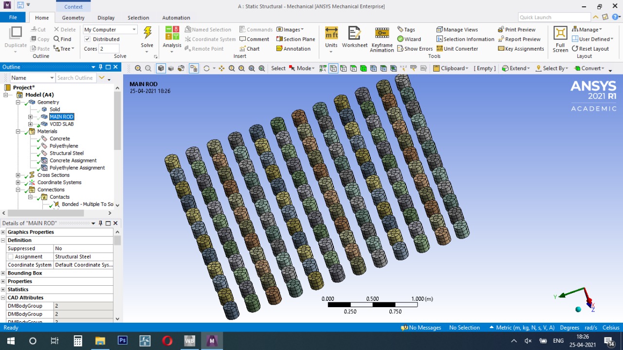
Fig 10 Total deformation
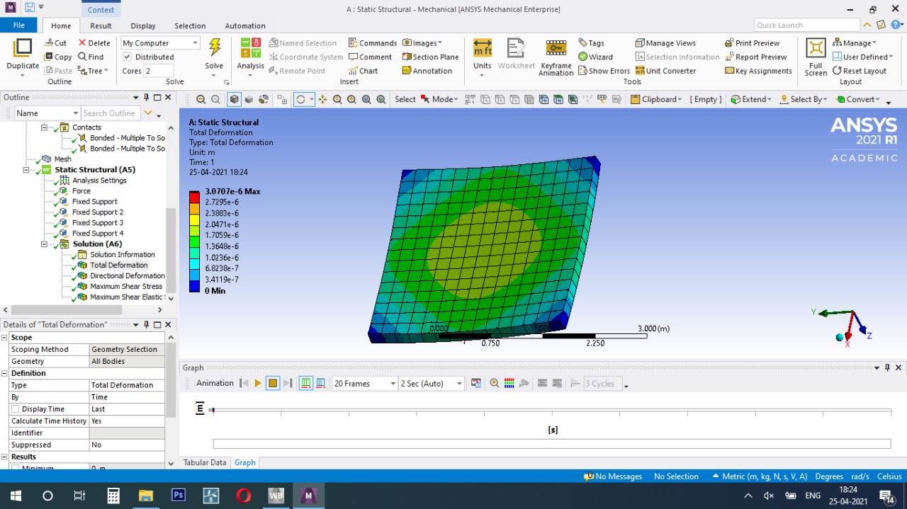
Fig 11 directional deformation in voided slab
V. RESULT AND DISCUSSION
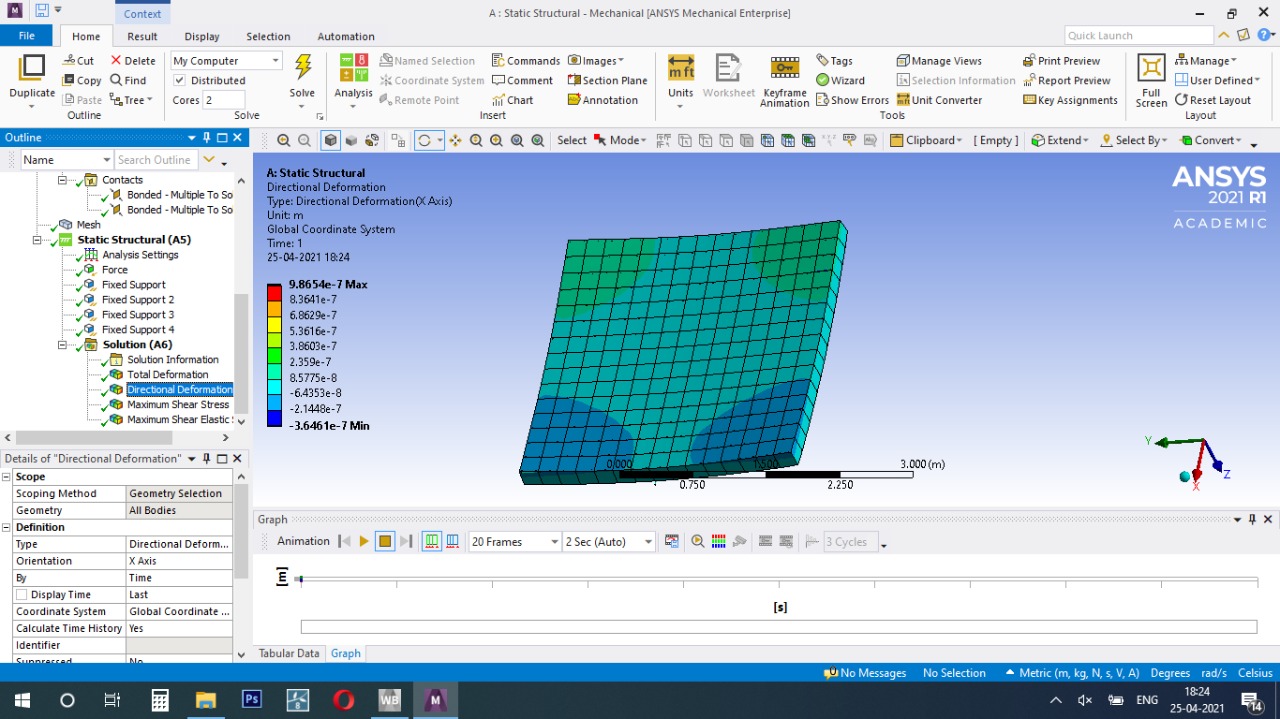
The deformations developed in the solid slab are comparatively less than the bubble deck slab the variations are shown in table 2 whereas the stresses developed in the solid slab are comparatively higher in case of solid slab. The moments developed in xx direction (M11), in yy direction (M22), in xy direction (M12), the shear forces developed in xz direction (V13), in yz direction (V23), the maximum stresses that are developed in the slab (SMAX), and the deflections (U3).
Table 2 Comparison of conventional slab and voided slab
|
Slab |
Load (KN)
|
Deflection (mm)
|
Weight (Kg)
|
|
Conventional slab |
260
|
8.70
|
321 |
|
Voided slab |
320
|
9.20
|
242 |
VI. MODELLING OF BEAMS
Four beams are modelled and analyzed in the study, a solid concrete beam, and three voided beams with varying rib size. The beams are 1800mm in length and 150mm by 200mm in cross section. All the beams are modelled with identical reinforcement pattern. The reinforcement is made of 2 numbers of 12mm diameter rod and 2 numbers of 16mm diameter rod with 8mm stirrups at 125mm centre-to-centre. The shape of void former is taken as cylinder with 30mm radius and 100mm height placed at the centre of the beam which gives a symmetrical cross-section. For the first voided beam, the rib size is provided as per Indian standards as 65 mm and for the second, the rib size is reduced to 60mm and by doing so, number of void formers is increased by 1, and for the last voided beam, the rib size is reduced to 55mm and again the number of void formers is further increased by 1.
|
Designation |
Rib Size |
No. of. voids |
Dimensions |
|
Solid beam |
- |
- |
150mm*200mm*1800mm |
|
Voided beam (65) |
65mm |
13 |
|
|
Voided beam (60) |
60mm |
14 |
|
|
Voided beam (55) |
55mm |
15 |
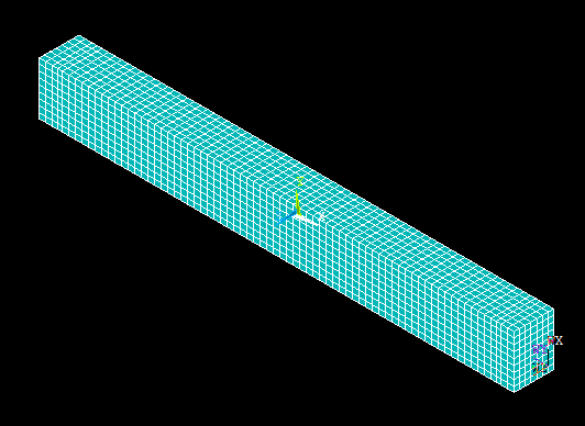
Fig 12 Meshing of Solid Beam
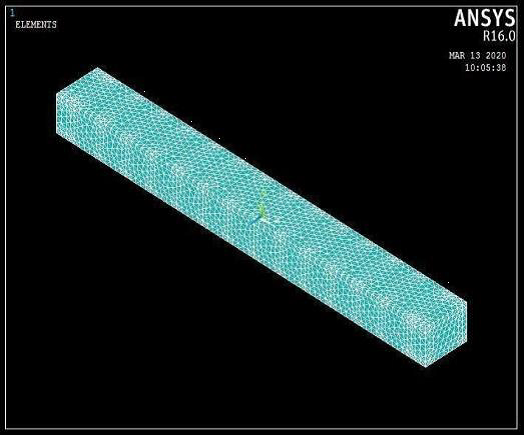
Fig 13 Meshing of Voided Beam
A. Loading and Boundary Conditions
The Flexure test or two point loading test is done on the beams to study the flexural behaviour. The beam is simply supported on two ends and two point loads are subjected on the beams at one third of the span from each end of the beam. The length of the beam between two point loads is subjected to pure flexure and failure takes place by bending. The displacement is arrested on all the three directions on one end and only on Y-direction on the other end, achieving the simply supported conditions. A load of 80kN is applied on the beam element and the analysis is carried out.
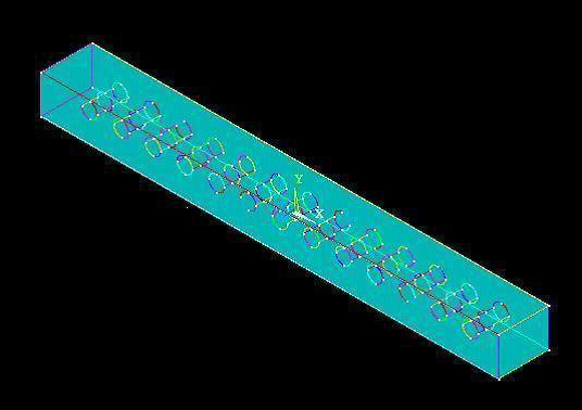
Fig 14 Modelled Voided Beam
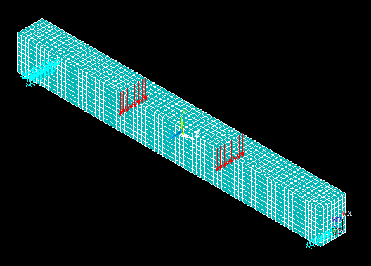
Fig 15 Loading and boundary conditions of solid beam
The modelled beams are meshed and loading and support conditions are given. The modelled beams are run by the ANSYS software. T results are obtained from the analysis run from the software.
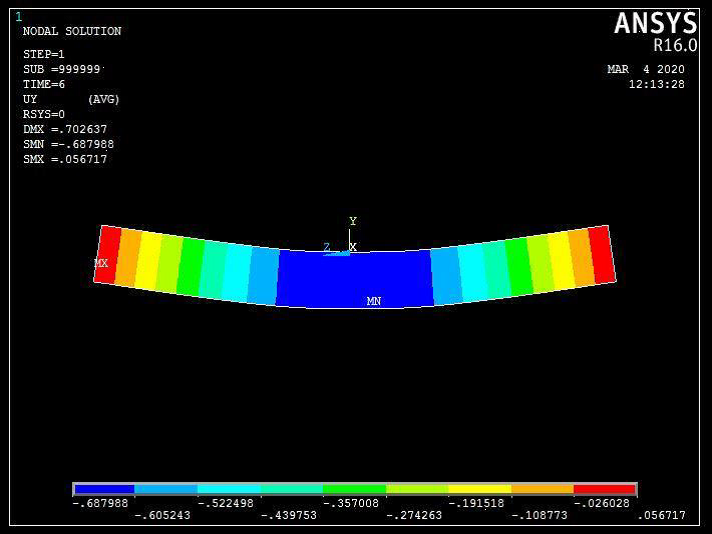
Fig 16 Displacement of Solid beam
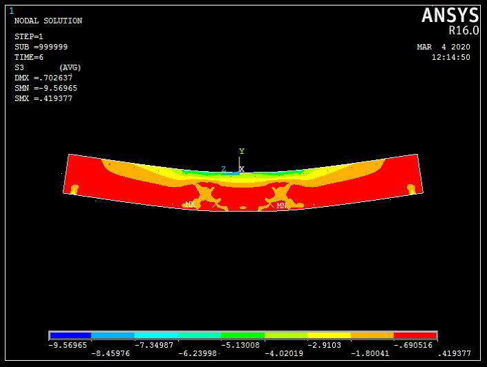
Fig 17 Stress distribution of Solid Beam
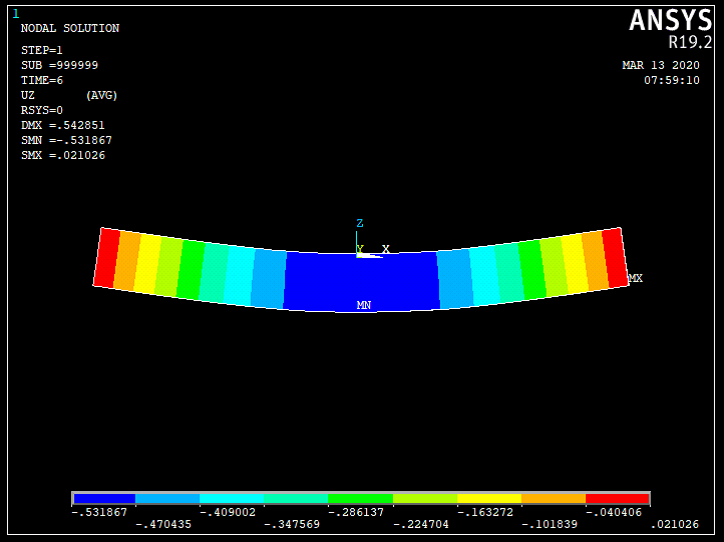
Fig 18 Displacement of Voided Beam65
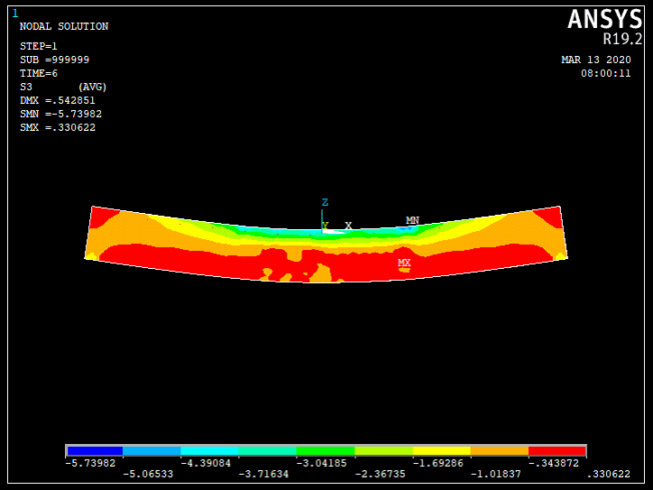
Fig 19 Stress distribution of Voided Beam65
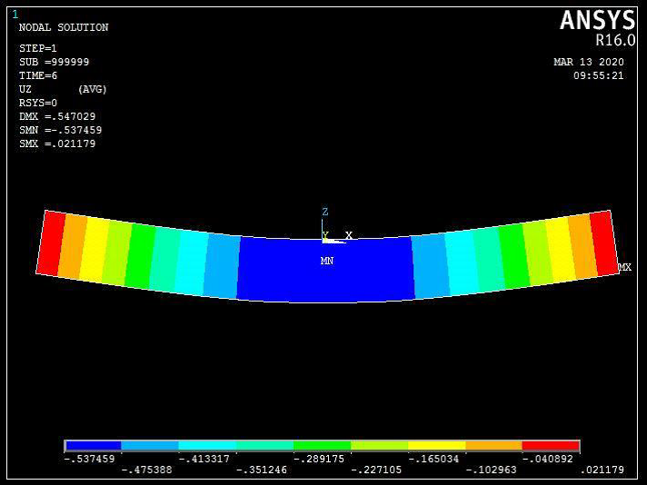
Fig 20 Displacement of Voided Beam60
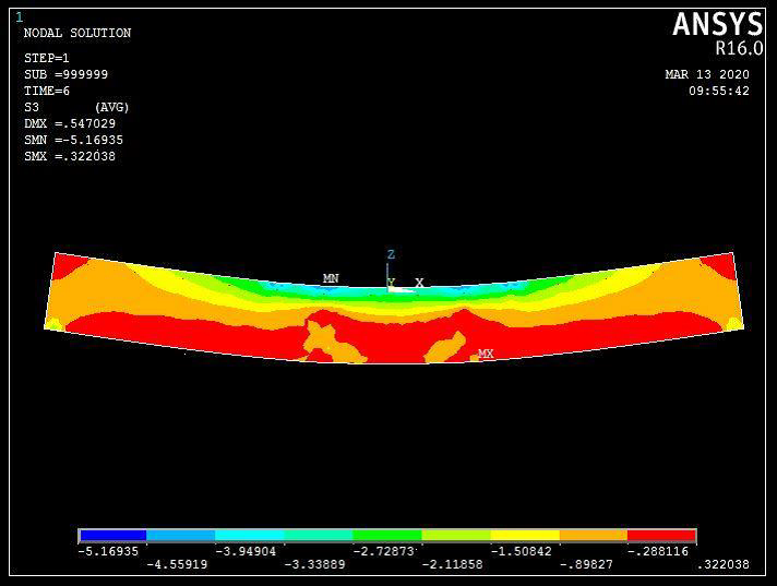
Fig 21 Stress distribution of Voided beam 60
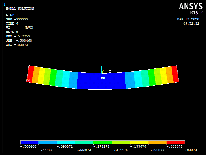
Fig 22 Displacement of Voided Beam 55
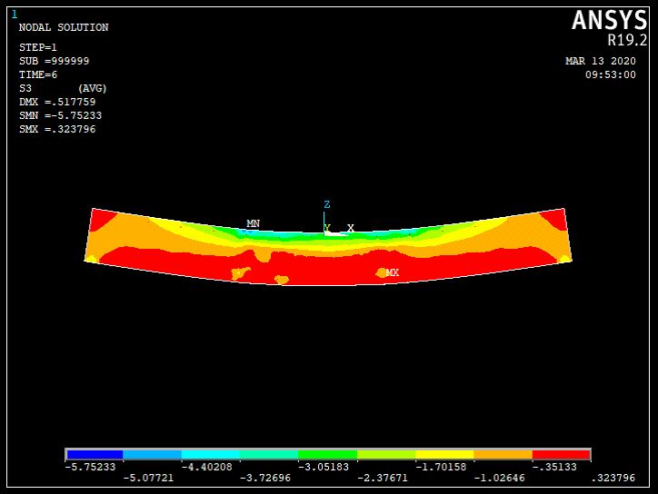
Fig 23 Stress distribution of Voided Beam 55
VII. RESULT AND DISCUSSION
The beams are modelled and analyzed in the ANSYS software and the results are arrived. From the results of the software, the following conclusions were made.
- The displacement of the VB65 is marginally higher than the specimen SB in the elastic region of loading. This is due to reduction in moment of inertia of the section due to the presence of voids.
- The displacements of VB60 and VB55 are greater than VB65 beam. The presence of more voids in the specimens VB60 and VB55 may be the reason for higher displacement.
- The displacement of VB55 is greater than VB65 but it is smaller than VB60 beam. The displacement is reduced by reducing the rib size from 60mm to 55mm. The arrangement of voids is similar in VB65 and VB55 and different from VB60.
- Stress distribution of the beams VB65 and VB55 are similar to each other but differ with VB60 beam.
Behaviour of the VB65 beam and the VB55 beam are similar. It is also to be compared with the solid reinforced concrete beam to study the effect of size of the rib on the flexural behaviour. A lot of savings in concrete can be ensured in major projects like bridges, multi storey structures, pre-fabrication units etc. The self-weight of the structures can be reduced by up to 35 percent and leads to an economical project scheme.
Conclusion
A. Voided Slab And Conventional Slab 1) Voided slabs are more economical than conventional slabs because they require less reinforcement and smaller members for the columns, beams, and footings. 2) Voided slabs are lighter than conventional slabs, which can reduce the overall weight of a building and the amount of concrete and steel use. 3) Voided slabs are also precast and manufactured in a factory, which reduces the time it takes to erect a building. 4) Voided slabs can reduce concrete consumption by up to 40% without significantly affecting load capacity. 5) Voided slabs can reduce the CO2 emissions and embodied energy of a construction. 6) The stiffness of a voided flat plate slab decreases as the thickness of the slab increases. B. Voided Beam And Solid Beam 1) Voided beams are lighter than solid beams because they are not completely filled with concrete. For example, a conventional reinforced concrete beam that weighs 75.55 kg can be reduced to 43.30 kg by using a voided square beam. 2) Voided beams can have similar load carrying capacity to solid beams. For example, a voided beam with a concrete strength of 33.2 MPa can have about 98% of the moment capacity of a solid beam with the same concrete strength. 3) Voided beams can have less deflection than solid beams. For example, voided slabs can have up to 16% less deflection at the design load than solid slabs.
References
[1] Mr Yadav Jaideep Purushottam, Prof Tambe Yogesh Hemantkumar “Analytical study of solid flat slab and voided slab using ANSYS Workbench” International Research Journal of Engineering and Technology (IRJET) e-ISSN: 2395 -0056 Volume: 03 Issue: 10 | Oct -2016 [2] Abhija Mohan, Archana Sukumaran “Performance Analysis of Bubble Deck Slab Using Elliptical Balls” International Journal of Engineering Research & Technology (IJERT) Special Issue – 2018. [3] P. Prabhu Teja, P. Vijay Kumar, S. Anusha “Structural Behavior of Bubble Deck Slab” International Conference On Advances In Engineering, Science And Management (ICAESM -2012) March 30, 31, 2012. [4] Samantha.Konuri, Dr.T.V.S.Varalakshmi “Review on Bubble Deck Slabs Technology And Their Applications” International journal of scientific & technology research Volume 8, Issue 10, October 2019. [5] Abhishek R. Pandharipande, N. J. Path “Analytical And Experimental Investigation On Voided Slab” International journal of scientific & technology research Volume 8, Issue 8, August 2019. [6] Sameer Ali, Manoj Kumar “Analytical study of conventional slab and bubble deck slab under various support and loading conditions” International Research Journal of Engineering and Technology (IRJET) Volume: 04 Issue: 05 | May -2017. [7] R.Sagadevan, B.N.Rao “Experimental and analytical investigation of punching shear capacity of biaxial voided slabs” August 2019. [8] Miss. Shruti Pandkar , Prof. Giridhar Narule “Comparative Study of Experimentation on Voided Slab Using ANSYS Workbench 14.5” International journal for research & development in technology Volume7 Issue 5 (May-17). [9] Snehal Kitture1 , Nakul Kabra “Experimental Study on Voided Biaxial Slab and its application” International journal of trend in scientific research and development. Volume 2 Issue 1. [10] Pathan Taha Mehboob Khan, Pathan Altamash Mehboob Khan “Experimental Study on Bubble Deck Beam” ISSN 2321 3361 © 2019 IJESC, volume 9 Issue no 6.
Copyright
Copyright © 2024 Srivani. M, D. K. Ramadevi. This is an open access article distributed under the Creative Commons Attribution License, which permits unrestricted use, distribution, and reproduction in any medium, provided the original work is properly cited.

Download Paper
Paper Id : IJRASET65181
Publish Date : 2024-11-12
ISSN : 2321-9653
Publisher Name : IJRASET
DOI Link : Click Here
 Submit Paper Online

