Ijraset Journal For Research in Applied Science and Engineering Technology
- Home / Ijraset
- On This Page
- Abstract
- Introduction
- Conclusion
- References
- Copyright
Analytical Analysis of Buckling Of Layered Composite Columns
Authors: Mr. Mayuresh Patil, Dr. S. M. Shiyekar
DOI Link: https://doi.org/10.22214/ijraset.2024.63721
Certificate: View Certificate
Abstract
Lightweight composite construction is of great interest in the design and manufacture of spacecraft and marine vehicles because of high specific stiffness and strength. In addition, sandwich construction offers enhanced corrosion resistance, noise suppression and reduction in life-cycle costs. There are several issues and questions related to the use of composite construction that require attention and answers. One of the important issues is the prediction of buckling loads, under either static or sudden load application. For the static case, closed form solutions are derived for a symmetric composite column under axial compression and for various boundary conditions. In this study, improved analytical models are developed to characterize interface behavior of layered composite column-type structures. The mechanics models of the bonded interface with and without adhesive layer are established, from which the interface fracture, delamination buckling, free vibration and stress analysis across the adhesive layer of corresponding interface are studied.
Introduction
I. INTRODUCTION
Buckling is a critical issue for structural stability in structural design. In many engineering structures such as columns, beams, or plates, their failure develops not only from excessive stresses but also from buckling in most of the buckling analyses, various applied loads, structural and material properties are considered certain. However, in reality, these parameters are uncertain. [1]
Currently, the application of composite layered systems is increasing tremendously in various engineering industries, such as mechanical and structural engineering.
This is because composite layered structures have a lot of compensation compare among the conventional structures. [2] The benefits of using layered composite materials are high strength-to-weight and stiffness-to-weight ratios, corrosion resistance, design flexibility, durability, and so on.
Spite their many attractive properties, one of the main drawbacks of using layered composites is that it is almost impossible to create perfectly strong bonds between layers. This results in interlaminar slippage and has a significant impact on the mechanical behavior of the composite structure.
A composite material is made up of two or more components and has qualities that none of its component materials might have achieved on their own. [3] In such materials the main load bearing members are the fibres. The matrix has low modulus and high elongation and it provides flexibility to the arrangement keeps the fibres in position and protects them from the external forces of the environment. [4]
II. RESEARCH METHODOLOGY
- Formulation of Higher Order Theory and prepare complete analytical solution for Buckling of covered complex column.
- Modeling of buckling of layered composite column in ABAQUS for isotropic material and validation of results with available literature.
- Validation of ABAQUS results with Higher Order Theory for various parameters.
- Modeling of new geometry of Buckling of layered composite column for a range of boundary condition and loading circumstances.
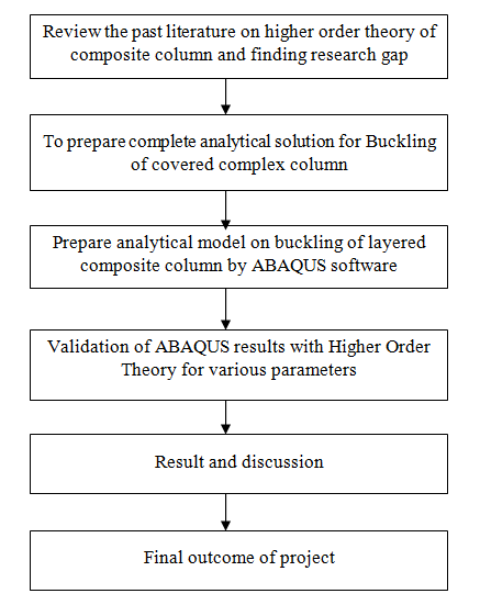
1 Flowchart o methodology
II. LITERATURE REVIEW
- T. Kant and H.S. Patil (1991) created the application of a higher-order shear deformable hypothesis, which accept a practical cross-sectional miss hapening design and disposes of the make utilize of a shear refinement coefficient, is displayed to assess the buckling forces of a symmetric, 3-layered, essentially upheld, sandwich column when subjected to compressive edge forces. A stopped up frame arrangement of the harmony conditions is gotten by utilizing Von Karman strain uprooting relations within the variety report of the on the whole potential vitality and dismissing any extending of the center line. The comes about, when compared with those gotten from Euler-Bernoulli and Timoshenko speculations, appear that the high shear deformability of the center essentially diminishes the buckling stack, highlighting the viability of a better arrange hypothesis
- Ever J. Barbero and loannis G. Raftoyiannis (1993), developed analytical models for several local buckling modes under axial and shear loading, taking the flange-web communication into account, are developed. Test information relating anticipated and watched behavior are displayed for a few commercially accessible auxiliary shapes. Disappointment envelopes are created for box- and I-shape FRP columns and pillars. The expository models displayed can be utilized to anticipate the execution of any unused refined fabric. The Rayleigh-Ritz method is used in this work to analyze anisotropic flanges of box and I-beams. The anisotropy of the fabric is introduced by ± 45° angle-ply layers introduced recently by cultured manufacturer to improve the buckling strength of columns as suggested by this investigation.
- Michael P. Nemeth (1995), We have presented a parametric delving of the buckling behavior of infinitely long, symmetrically stacked anisotropic plates under combined loading. This work center on the communication of a constant magnitude subcritical (stable) slight load state with a main destabilize load of increasing magnitude until buckle occur. The oodles careful in this report are consistent axial compression, unadulterated in-plane bending, slanting stress and density, and shear. The results obtained using a non-intensive special analysis suitable for parametric study of simple clamped support panels is presented. In particular, results for [±45] s-graphite epoxy laminates are shown. It is highly anisotropic and representative of laminates worn for spacecraft application. In addition, general buckling design charts for a extensive choice of dimensionless parameters suitable for a wide variety of laminate structures are presented. These results demonstrate universal behavioral trend particularly for orthotropic slabs and the effect of bending anisotropy on slabs subjected to various mutual load circumstances. A key finding of this learn is that the effect of winding anisotropy on plate buckling stiffness can be drastically stronger for plates loaded in grouping than for lamella loaded with one component.
- G.A. Kardomateasa, et.al. (2002), Developed theoretical predictions of buckle loads for sandwich pillars with metal and laminate skins & bubbles or honeycomb cores. Axial compressive load is uniform, which is applied statically (very slowly) and suddenly with a constant amount and unlimited duration (step load). The belongings of length and boundary conditions are evaluated and fallout is obtainable for: cantilever columns, simple columns and fixed column for quite a few lengths. Some 1ber materials are used for multi-layered exteriors. Two types of cores were investigated: alloy foam or hexagonal glass/phenolic honeycomb. The facings are Boron/Epoxy, Graphite/Epoxy and Kevlar/Epoxy laminates with 0?orientation with high opinion to the pillar axis and a metallic one made out of aluminum. These various materials are employed to provide comparative data that can be old in design. Results, for the stationary case are generated by computer codes as well as by the use of closed form theoretical solutions.
IV. THOEORY OF CFST COLUMN
A. Behaviour Of CFST Columns
The ultimate load capacity and stress-strain relationship of a CFST column is influenced by complex interactions between the steel pipe & concrete core components. In short columns such actions are govern by the force and characteristics of the equipment, while for slender columns mechanical instability is a consideration. As the focus of thesis is on the confinement effects in short columns, the structural mechanism by which confinement conditions develop and identification of effective parameters, shall be addressed.
Short amalgamated cues exhibit a misprision implement character by steel yielding and concrete cracking. Columns of medium length are inelastic and do not work due to partial yielding of steel, cracking of concrete during compression, also cracking of existent during tension.
Stocky concrete filled tubes are also susceptible to local buckling of the outer skin, and this is of importance in very thin-walled tubes which are nowadays often used in building construction. A short or stocky pillar is so short that flexural buckling will not occur, although local buckling may occur. [5] Stocky pillar are calculated primarily on the material strengths of the concrete and steel elements. The column is usually defined as a structural member who carries only concentric axial compression. The associate is a steel element and is subjected to bending as well as axial compression, as occurs when the weight is functional eccentrically; it is referred to as a beam-column.
The various national standards present load moment interaction equations which are slenderness dependent, and which must be satisfied for the strength limit state. Composite members subject to both compression and bending are referred to as pillars. Because of the presence of together steel & concrete in a composite column, the behaviour of such a member is akin both to a steel beam column and a RC pillar. Generally speaking, short or stocky composite columns are treated by the reinforced concrete approach based on section material strengths. Slender composite columns, which do not contain substantial bending actions are treat by the steel approach which is base on a design strength that is exaggerated by the slenderness of the column. There are a few structural considerations that must be borne in mind when comparing and contrasting the fundamental behaviour of encased columns plus CFST. Firstly, concrete filled strengthening cylinder s are susceptible to local buckling of the steel skin, the prospect of which in many cases is very thin. The second point pertains to the side imprisonment provided by the tube to the expansion of the concrete core in compression, which enhances the strength of short columns, but it is insignificant in slender pillar. Thirdly, the steel skin inhibits the egress of moisture that contributes to creep and reduction effects. Research into monitoring the time dependent deformations of concrete filled tubes has indicated a reduced tiptoe & decrease induced response. In all column analysis approaches second-hand at both ultimate and serviceability limits, it is unspecified that there is full interaction between the concrete element and the steel element. [6]
B. Short Term Behaviour
In a small concentrically laden CFST, the concrete heart of the pillar is subjected to a confine stress, with as a consequence the pillar be able to bear significantly larger axial forces than if the concrete was unconfined. The results of triaxial tests on concrete have illustrated this, where concrete subjected to a lateral confining pressure can carry a greater axial load than unconfined concrete. Of course, this is utilized in reinforced concrete construction where spirally reinforced columns provide a lateral stress that increases the axial load carried by the concrete core.
However, the behaviour of an axially laden strengthening cylinder filled with concrete will vary according to the method in which the ends of the member are loaded as exposed in Figure 3.1. Essentially, there are three fundamentally different methods of applying the loading, and these are discussed below.
C. Load the Steel and not the Concrete
This condition of loading may not increase the axial ability of the column above that of the strengthening cylinder alone, because the Poisson’s effect causes the strengthen cylinder to separate from the concrete, once the adhesive chemical bond flanked by the concrete and steel has exceeded. The column will generally fail at the maximum load which the void strengthening cylinder alone can carry, but the concrete core may tend to delay the column local buckling. For slender columns, the failure load will augment significantly due to the augment in flexural stiffness.
D. Load the Concrete and not the Steel
In this principle, which is the most favourable loading method, the concrete takes the maximum load as the steel does not resist axial load, but only provides a confining stress to the concrete in an analogous manner to a spirally RC pillar. However, since there is some adhesion between the steel plus concrete, the condition is hard to attain as some axial force is produced in the steel.
E. Load the Steel and Concrete
This is the method most often encountered in practice, and it may be enforced by welding stud shear connectors to the inside of the steeltube where practicable. If the steel is axially stressed in compression as well as circumferentially because of the expansion of the concrete, it will be subjected to a state of biaxial stress which, in accordance with the von Mises’ yield criterion, determination reduces the yield stress in the circumferential direction. This has the consequence of lowering the confine effect, and hence reduces the maximum load on the concrete.
Though the reduction in the confining effect is offset, since the steel now carries some of the compressive force the load-carrying capability of the column is increased by this steel & concrete. [7]
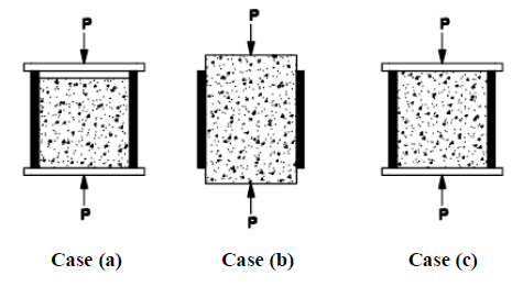
Loading Conditions of Specimens
F. Load Transfer Mechanism
The maximum axial load-bearing capacity of CFST has been shown to be greater than the sum of unbonded steel concrete at failure loads. The increased breaking load is caused by the restraining effect of the steel pipe on the concrete. The load-bearing behavior of concrete-filled pipe profiles is greatly affected by the difference in Poisson's ratio between steel pipe and concrete. At the initial stage of loading, the Poisson's ratio of concrete is lower than that of steel. Therefore, steel pipes have no restrictive impact on concrete. With increasing longitudinal expansion, the transverse expansion of concrete gradually becomes larger than that of steel pipe. At this stage, the concrete is triaxially clamped and the steel pipe he is biaxially clamped. A steel pipe in a biaxially stressed state cannot withstand the normal yield stress and loads are transferred from the steel pipe to the concrete. In the first loading phase, steel pipes withstand most loads. At this stage there is load transfer from the steel pipe to the concrete. Steel pipes have a gradual decrease in load distribution until the concrete reaches its maximum compressive strength. After the initial loading phase, the load is redistributed from the concrete to the steel pipe and the steel exhibits hardening behavior roughly corresponding to the uniaxial stress-strain hardening ratio. [8]
V. RESULT AND DISCUSSION
A. Analytical Load Carrying Capacity of Circular Short Column
Load Carrying Capacity of Circular Short Column
|
Sr. No |
Diameter (mm) |
Thickness (mm) |
Inner Diameter (mm) |
Length (mm) |
Load Carrying Capacity (KN) |
Load to Area Ratio |
|
1 |
80 |
4 |
72 |
90 |
697.31 |
0.139 |
|
2 |
80 |
4 |
72 |
95 |
634.9 |
0.126 |
|
3 |
80 |
4 |
72 |
100 |
599.488 |
0.119 |
|
4 |
80 |
4 |
72 |
150 |
382.88 |
0.076 |
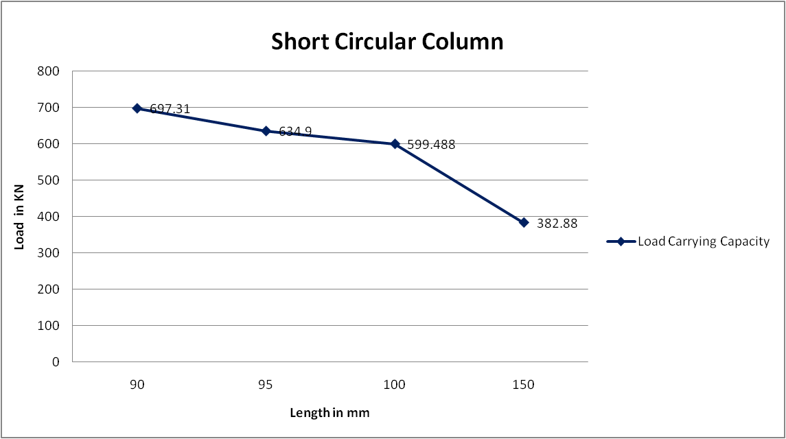
Load Carrying Capacity of Circular Short Column
Load Carrying Capacity of Circular Long Column
|
Sr. No |
Diameter (mm) |
Thickness (mm) |
Inner Diameter (mm) |
Length (mm) |
Load Carrying Capacity (KN) |
Load to Area Ratio |
|
1 |
80 |
4 |
72 |
200 |
264.42 |
0.053 |
|
2 |
80 |
4 |
72 |
250 |
193.91 |
0.039 |
|
3 |
80 |
4 |
72 |
300 |
148.038 |
0.029 |
|
4 |
80 |
4 |
72 |
350 |
123.39 |
0.025 |
|
5 |
80 |
4 |
72 |
400 |
105.9 |
0.021 |
|
6 |
80 |
4 |
72 |
450 |
833.8 |
0.166 |
|
7 |
80 |
4 |
72 |
500 |
708.06 |
0.141 |
|
8 |
80 |
4 |
72 |
550 |
607.31 |
0.121 |
|
9 |
80 |
4 |
72 |
600 |
527.94 |
0.105 |
|
10 |
80 |
4 |
72 |
650 |
508.38 |
0.101 |
|
11 |
80 |
4 |
72 |
700 |
417.46 |
0.083 |
|
12 |
80 |
4 |
72 |
750 |
367.7 |
0.073 |
|
13 |
80 |
4 |
72 |
800 |
331.63 |
0.066 |
|
14 |
80 |
4 |
72 |
850 |
306.48 |
0.061 |
|
15 |
80 |
4 |
72 |
900 |
273.45 |
0.054 |
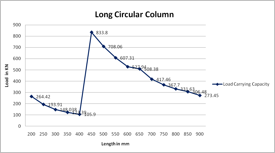
Load Carrying Capacity of Circular Long Column
B. Analytical Load Carrying Capacity of Rectangular Short Column
Load Carrying Capacity of Rectangular Short Column
|
Sr. No |
Longer Dim D (mm) |
Thickness (t) |
Shorter Dim B (mm) |
length(mm) |
Load Carrying Capacity (KN) |
Load to Area Ratio |
|
1 |
80 |
4 |
40 |
90 |
264.35 |
0.08 |
|
2 |
80 |
4 |
40 |
95 |
249.71 |
0.08 |
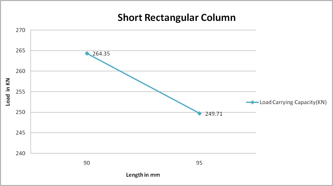
Load Carrying Capacity of Rectangular Short Column
Load Carrying Capacity of Rectangular Long Column
|
Sr. No |
Longer Dim D (mm) |
Thickness (t) |
Shorter Dim B (mm) |
Length(mm) |
Load Carrying Capacity (KN) |
Load to Area Ratio |
|
1 |
80 |
4 |
40 |
100 |
238.35 |
0.07 |
|
2 |
80 |
4 |
40 |
150 |
141.58 |
0.04 |
|
3 |
80 |
4 |
40 |
200 |
104.47 |
0.03 |
|
4 |
80 |
4 |
40 |
250 |
849.01 |
0.27 |
|
5 |
80 |
4 |
40 |
300 |
664.4 |
0.21 |
|
6 |
80 |
4 |
40 |
350 |
542.75 |
0.17 |
|
7 |
80 |
4 |
40 |
400 |
428.35 |
0.13 |
|
8 |
80 |
4 |
40 |
450 |
343.029 |
0.11 |
|
9 |
80 |
4 |
40 |
500 |
285.11 |
0.09 |
|
10 |
80 |
4 |
40 |
550 |
242.26 |
0.08 |
|
11 |
80 |
4 |
40 |
600 |
210.93 |
0.07 |
|
12 |
80 |
4 |
40 |
650 |
183.47 |
0.06 |
|
13 |
80 |
4 |
40 |
700 |
160.65 |
0.05 |
|
14 |
80 |
4 |
40 |
750 |
141.3 |
0.04 |
|
15 |
80 |
4 |
40 |
800 |
131.14 |
0.04 |
|
16 |
80 |
4 |
40 |
850 |
112.52 |
0.04 |
|
17 |
80 |
4 |
40 |
900 |
101.76 |
0.03 |
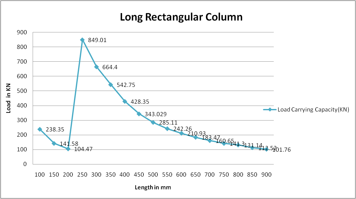
Load Carrying Capacity of Rectangular Long Column
Conclusion
The buckling analysis of composite laminated plates under uniaxial compression using finite element analysis has been studied. The effect of aspect ratio, side to thickness ratio, modulus ratio, boundary conditions, and fiber orientations on the maximum critical buckling load for three different resources at optimum number of layers has been investigated. From the results; it was observed that, the non dimensional critical buckling load increases with increase of side to thickness ratio and modulus ratio under uniaxial compression due to the effect of shear deformation
References
[1] A. Ghorbanpour Arani, Sh. Maghamikia, M. Moham madimehr and A. Arefmanesh, “Buckling Analysis of Laminated Composite Rectangular Plates Reinforced by Swcnts Using Analytical and Finite Element Methods”, Journal of Mechanical Science and Technology, Vol. 25, Pp. 809-820, 2011. [2] Ever J. Barbero and loannis G. Raftoyiannis, “Local buckling of FRP Beams and columns” Journal of Materials in Civil Engineering, Vol. 5, No.3, August, 1993. [3] Fangliang Chen, “Interface Mechanics of Layered Composite Beam-Type Structures”, 2011. [4] G. A. Kardomateas, G. J. Simitses, L. Shen, R Lia, “Buckling of Sandwich Wide Columns”, International Journal of Non-Linear Mechanics, Vol. 37, Pp. 1239-1247, 2002. [5] K. Mallikarjuna Reddy, B. Sidda Reddy, R. Madhu Kumar, “Buckling Analysis of Laminated Composite Plates Using Finite Element Method”, International Journal Of Engineering Sciences & Research Technology, Vol. 2, Pp. 3281-3286, 2013. [6] Kasim A Korkmaz, Fuat Demir and Hamide Tekeli, “Uncertainty modelling of critical column buckling for reinforced concrete buildings”, Indian Academy of Sciences Sadhana, Vol. 36, Part 2, Pp. 267–280, April 2011. [7] Lars Fiedler, Walter Lacarbonara, Fabrizio Vestroni, “A generalized higher-order theory for multi-layered, shear-deformable composite plates” Published online on 10 March 2009 © Springer-Verlag 2009 [8] Michael P. Nemeth, “Buckling Behavior of Long Anisotropic Plates Subjected to Combined Loads.” NASA Technical Paper, Vol. 3568, 1995. [9] Nguyen Thi Phuong, Dao Huy Bich, “Buckling Analysis of Eccentrically Stiffened Functionally Graded Circular Cylindrical Thin Shells Under Mechanical load”, VNU Journal of Mathematics – Physics, Vol. 29, No. 2, 55-72, 2013. [10] P. Ravikanth Raju, J. Suresh Kumar, M. V. Lakshmi Prakash “ Buckling Analysis of Smart Material Plates Using Higher Order Theory”, Journal of Mechanical and Civil Engineering, Vol. 11, Issue, Pp. 55-60, 2014.
Copyright
Copyright © 2024 Mr. Mayuresh Patil, Dr. S. M. Shiyekar. This is an open access article distributed under the Creative Commons Attribution License, which permits unrestricted use, distribution, and reproduction in any medium, provided the original work is properly cited.

Download Paper
Paper Id : IJRASET63721
Publish Date : 2024-07-22
ISSN : 2321-9653
Publisher Name : IJRASET
DOI Link : Click Here
 Submit Paper Online

