

Ijraset Journal For Research in Applied Science and Engineering Technology
Comparative Analysis of Circumferential Stress in Horizontal Pressure Vessels Using Finite Element Analysis
Authors: Dr. Rohit P. Jadhav, Dr. Yogesh G. Kamble, Nilesh M. Mahajan, Vipul P Rathod
DOI Link: https://doi.org/10.22214/ijraset.2025.66563
Certificate: View Certificate
Abstract
The horizontal pressure vessels are supported by saddle supports, which are designed in accordance with Zick’s theory in ASME code. However, this theory uses horizontal pressure vessels as simply supported beams, and it ignores the impact of changes in the vessel\'s size and shape. It is challenging to compute the loads and stress concentrations in a vessel caused by saddle support using conventional methods. Traditional techniques cannot accurately replicate the stress distribution in a saddle or vessel, which is crucial for identifying safety critical locations that will support local strengthening as a first step in optimization. Traditional methods used in this work include design by formulae (using Zick\'s formulas) and design by FEA (also known as DBA-Design by analysis).
Introduction
I. INTRODUCTION
A pressure vessel is a closed container designed to hold gases or liquids under internal or external pressure. Pressure vessels are designed to operate safely at a specific pressure and temperature. A saddle support is used to support the horizontal pressure vessels, as saddle is restricting expansion of pressure vessel, stresses are generated at pressure vessel and saddle junction. If saddle is not flexible enough then it will generate higher stresses (stress concentration) at junction and this will lead to failure of vessel. Therefore, the design of a saddle and determination of the stresses induced in saddle and at saddle vessel interface is an important step during the design of a horizontal pressure vessel. The ASME pressure vessel code is providing design procedure for design of supports but the procedure mentioned in code is not useful in every situation and codes are failing to account every kind of load (can’t account loads such as seismic and others) and geometry. The forces acting on saddle support due to weight of horizontal pressure vessel and internal pressure of pressure vessel causes stresses in the saddle supports. The main purpose of this work is to perform a stress analysis of saddle support and different end closures effect on saddle support by using finite element analysis. In this project the high stress areas in saddles will be identified and care will be taken to reduce stresses. The stress analysis will be carried out by using finite element analysis software ANSYS. Pressure vessels are mounted vertically, inclined, horizontally on either fixed or movable supports but it is observed that supports may cause higher stress concentration in pressure vessels, if they are not properly selected or mounted. As shape, size and location of support is most important in reducing stress levels we have concentrated our work on supports. In this work saddle supported vessels are considered to be supported on stationary platform. Optimum location of saddle supports is found out with respect to length of pressure vessel also the effect of size and shape on stress levels in pressure vessels are found out. Procedure available in codes and literature as well as finite element analysis (DBA design by analysis) is used.
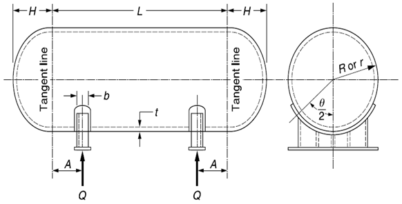
Figure 1. Horizontal Pressure Vessel Supported on Saddles
II. DESIGN BY CODES (ASME CODES)
Methodology for the determination of the stresses in the shell and heads of a horizontal vessel supported on saddles was first published by L. P. Zick. This procedure has been used, with certain refinements since that time, and is often called Zicks analysis, or the stresses are referred to as Zicks stresses. Zick presented a semi empirical analysis approach that has traditionally formed the basis of design of saddle supports for horizontal pressure vessels in a number of pressure vessel design codes.The main stresses to be considered in the design:
Longitudinal Bending:
S1 , longitudinal bending at saddles-without stiffeners, tension.
=
S2, longitudinal bending at saddles-without stiffeners, compression.
S3, longitudinal bending at saddles-with stiffeners.
S4, longitudinal bending at mid-span.
=
Tangential Shear:
S5, tangential shear-shell stiffened in the plane of the saddle.
S6, tangential shear-shell not stiffened, A > 0.5R.
S7, tangential shear-shell not stiffened, A ≤ 0.5R.
S8, tangential shear in head-shell not stiffened, A ≤ 0.5R.
Circumferential Bending:
S9, circumferential bending at horn of saddle shell not stiffened (L ≥ 8R).
S10, circumferential bending at horn of saddle-shell not stiffened (L < 8R).
Pressures stresses:
Longitudinal
Circumferential
|
Parameters |
Values |
|
Design pressures P |
0.2,0.4,0.6 & 0.7 Mpa |
|
Saddle width b |
101.60mm |
|
Saddle angle of contact θ |
125° |
|
Outside radius of shell R |
152.5 mm |
|
Shell thickness ts |
3 mm |
|
Length of vessel of tangent to tangent line |
900 mm |
|
Material |
SA 515-70 plate |
|
A |
276.60mm |
|
D |
5 mm |
|
G |
3 mm |
|
B |
305 mm |
|
F |
101.60 mm |
Table 1. Detailed dimensions of vessel and saddle support for studying circumferential stress
III. DESIGN BY ANALYSIS
The entire CAD model of the pressure vessel with saddle support is modelled in FEA software ANSYS as shown in Fig.2. CAD model of pressure vessel Finite element model of pressures vessel Meshed model: - The cad modelled prepared in ANSYS is meshed by using solid 45 and solid 95 elements as shown in Fig Boundary conditions: - Internal pressure is applied red colour indicates that internal pressure is being applied to the vessel and base plate area of two saddle supports is fixed in all directions as shown in Fig.2.below.
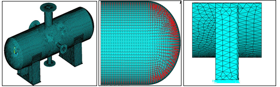
Figure 2. Finite Element Model & Boundary Conditions
Numerical results are calculated by using design by analysis approach (DBA) by using commercial finite element analysis package ANSYS. Circumferential stresses for pressures 0.2, 0.4, 0.6 and 0.7 Mpa are calculated and the results are shown in Table 2.
IV. RESULT AND DISCUSSION
To validate the analytical and CAE procedure an experimental setup is prepared and the experimental analysis is carried out from which test readings of micro-strain are noted and hoop stresses are calculated for different pressures for different saddle support locations shown in Fig.3.
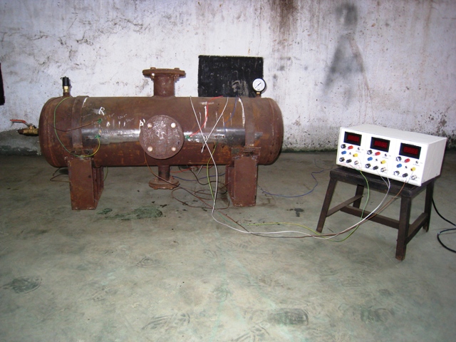
Figure.3. Experimental Setup
The results of the analysis of the case studies by the analytical, numerical and experimental methods are presented and compared in this section which is shown in Table 2.
|
Pressure |
D |
A |
Avg. strain |
Long. Stress |
Exp Hoop stress |
FEA Hoop stress |
Theory Hoop stress |
|
0.2 |
305 |
180 |
1.98E-05 |
4.165 |
8.33 |
12.22 |
9.46 |
|
0.2 |
305 |
225 |
2.27E-05 |
4.76 |
9.52 |
13.22 |
16.7 |
|
0.2 |
305 |
247.5 |
2.45E-05 |
5.145 |
10.29 |
15.34 |
20.9 |
|
0.2 |
305 |
292.5 |
2.87E-05 |
6.02 |
12.04 |
16.23 |
30.54 |
|
Pressure |
D |
A |
Avg. strain |
Long. Stress |
Exp Hoop stress |
FEA Hoop stress |
Theory Hoop stress |
|
0.4 |
305 |
180 |
4.08E-05 |
8.575 |
17.15 |
26.32 |
9.46 |
|
0.4 |
305 |
225 |
4.57E-05 |
9.59 |
19.18 |
27.87 |
16.7 |
|
0.4 |
305 |
247.5 |
4.97E-05 |
10.43 |
20.86 |
29.61 |
20.9 |
|
0.4 |
305 |
292.5 |
0.000055 |
11.55 |
23.1 |
30 |
30.54 |
|
Pressure |
D |
A |
Avg. strain |
Long. Stress |
Exp Hoop stress |
FEA Hoop stress |
Theory Hoop stress |
|
0.6 |
305 |
180 |
0.00007 |
14.7 |
29.4 |
33.06 |
9.46 |
|
0.6 |
305 |
225 |
7.42E-05 |
15.575 |
31.15 |
36 |
16.7 |
|
0.6 |
305 |
247.5 |
0.000077 |
16.17 |
32.34 |
39.62 |
20.9 |
|
0.6 |
305 |
292.5 |
7.97E-05 |
16.73 |
33.46 |
39.79 |
30.54 |
|
Pressure |
D |
A |
Avg. strain |
Long. Stress |
Exp Hoop stress |
FEA Hoop stress |
Theory Hoop stress |
|
0.7 |
305 |
180 |
7.23E-05 |
15.19 |
30.38 |
40.34 |
9.46 |
|
0.7 |
305 |
225 |
7.53E-05 |
15.82 |
31.64 |
48.06 |
16.7 |
|
0.7 |
305 |
247.5 |
8.42E-05 |
17.675 |
35.35 |
47.63 |
20.9 |
|
0.7 |
305 |
292.5 |
9.07E-05 |
19.04 |
38.08 |
50.45 |
30.54 |
Table 2. Comparison of hoop stress by analytical, numerical and experimental method
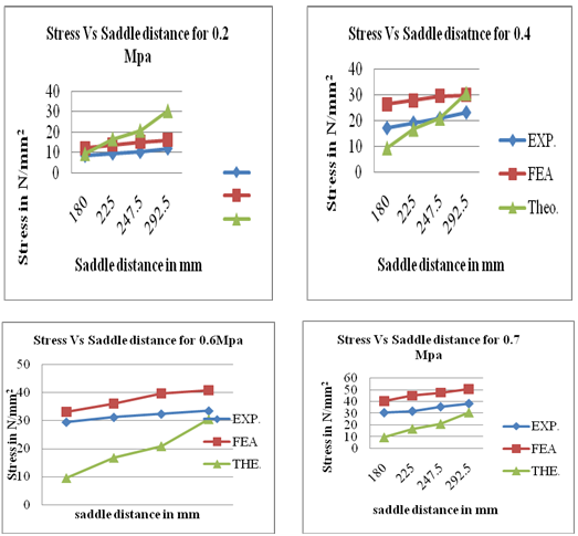
Figure.4. Graph of Stress Vs Saddle Distance for different Pressures
Conclusion
1) By the analytical (zicks analysis) approach it is concluded that optimum point of location of saddle supports from the tangent line head end to the centre of the saddle must be between 0.2 to 0.25L. 2) Only in first case Theoretical stresses are higher compared to experimental & FEA results. 3) In comparisons of the analytical, experimental and FEA results it is concluded that FEA results are higher than experimental and analytical results.
References
[1] L. P. Zick (1951), “stresses in large horizontal cylindrical pressure vessels on two saddle supports”, the welding journal research supplement, pp 959-970. [2] Shafique M.A. Khan (2010), “stress distributions in a horizontal pressure vessels and the saddle supports”, international journal of pressure vessels and piping 87 pp 239-244. [3] Jadhav, Rohit P., Abhijit A. Patil, and Shrikant B. Thorat. \"Emerging Trends of Digital Manufacturing in Bioimplants.\" 2023 IEEE Engineering Informatics (2023): 1-6. [4] Jadhav, Rohit, and Yogesh G. Kamble. \"Designing and Optimization of Mechanical Gripper Finger Using Finite Element Analysis.\" Techno-Societal 2016, International Conference on Advanced Technologies for Societal Applications. Cham: Springer International Publishing, 2022. [5] Dennis R. Moss (2004), “Pressure Vessel Design Manual-Third Edition”, Gulf Professional Publication. [6] K. Magnucki& J. B?achut (2003), “Flexible saddle support of a horizontal cylindrical pressure vessel,” International Journal of Pressure Vessels and Piping, Volume 80, Issue 3, pp 205-210. [7] El-Abbasi (2001), “Three-Dimensional Finite Element Analysis of Saddle Supported Pressure Vessels” international journal of mechanical science 2001, vol43, pp 29-43. [8] American Society of Mechanical Engineering, “boiler and Pressure Vessel code” 2007&10 sec VIII –Division II”.
Copyright
Copyright © 2025 Dr. Rohit P. Jadhav, Dr. Yogesh G. Kamble, Nilesh M. Mahajan, Vipul P Rathod. This is an open access article distributed under the Creative Commons Attribution License, which permits unrestricted use, distribution, and reproduction in any medium, provided the original work is properly cited.

Download Paper
Paper Id : IJRASET66563
Publish Date : 2025-01-18
ISSN : 2321-9653
Publisher Name : IJRASET
DOI Link : Click Here
 Submit Paper Online