Ijraset Journal For Research in Applied Science and Engineering Technology
- Home / Ijraset
- On This Page
- Abstract
- Introduction
- Conclusion
- References
- Copyright
Comparative Study on Seismic Analysis of Multistorey Building Using STAD Pro
Authors: Shruti Diliprao Raut, Prof. Vishal Sapate
DOI Link: https://doi.org/10.22214/ijraset.2023.54933
Certificate: View Certificate
Abstract
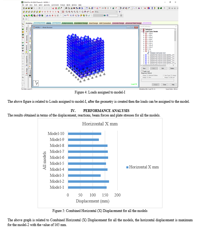
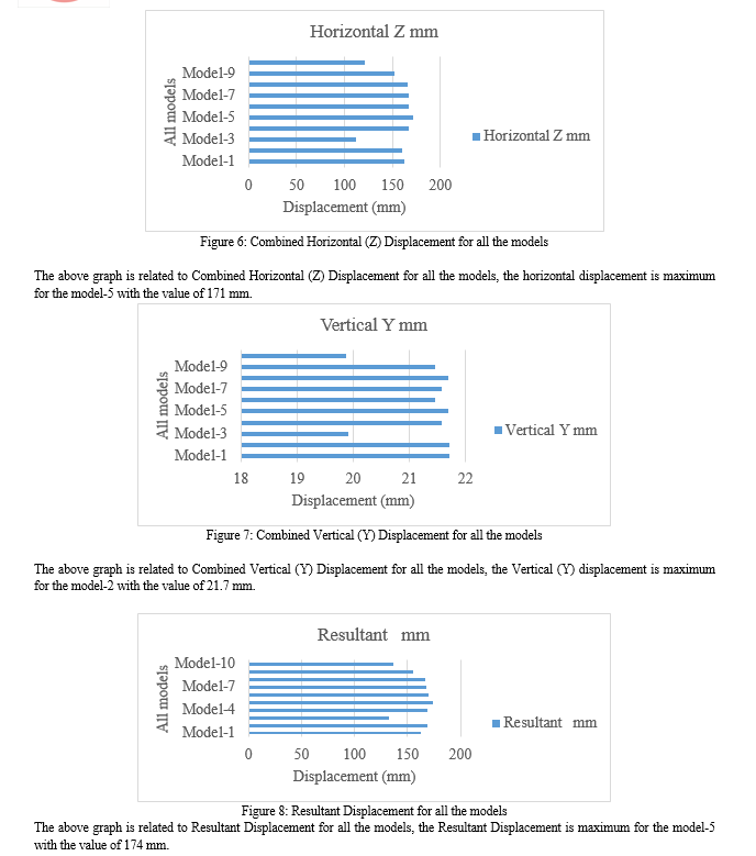
In this study, a comparative analysis of the seismic performance of a number of different building models was made using the STAAD.Pro software. The main purpose is to measure and compare the behavior of different buildings under seismic loads. The decision model includes changes in external properties such as shear walls at different locations, and analyzes are made for the link between horizontal and vertical forces, reactions and moments. The results provide useful information regarding the behavior of each structure under seismic forces. The maximum combined horizontal displacement (X) for the Model-2 is 165 mm, indicating significant movement in the X direction. The Model-5\\\'s maximum combined horizontal displacement (Z) is 171mm, meaning there is more horizontal movement in the Z direction. For Combined Vertical Displacement (Y), the Model-2 experienced the highest vertical displacement at 21.7mm. The results of this comparison provide important guidance for improving building configurations to improve their seismic performance. The results can assist in decision making during design and construction, making construction safer and stronger than many buildings in earthquake zones.
Introduction
I. INTRODUCTION
As part of this analysis, the maximum lateral slip for each wing should be calculated for concave angles. The sum of these values ??is equal to the space required between the blades for the blades to deflect in the worst possible way without impact. In this case, expansion joints are used to connect the blades. When each wing is treated as a separate model, the angle is often neglected [6]. When considering the vertical and lateral loads of the individual blades, the result of the angle of the force is not considered, making it difficult to change the difference between the angles without special connections and joints in the design [7].
Another design method currently used to appeal to soldiers at concave corners is to use the eight shape instead of the traditional 90° concave corner. When changing the angle of the angle, the resulting force decreases. "Securely interconnect the building between the tension lines and the resistor location to reduce torsion" [8]. Although this method addresses the re-entry issue more directly than the other methods above, it is not an adequate method to consider all the consequences. This is because the current design cannot fully determine the effect of the re-entry angle created on the load side.
These designs and simple designs are allowed by current building codes as they help improve sound or designs [9]. According to ASCE 7-10 , "Rotating irregularity is defined as the two planar planes of a structure being more than 15% of the overall structure of the structure in one direction. The diaphragm causes the diaphragm beams or buttresses to fail when the main line of the wall is moved by a portion of the outer wall [10]. When an irregularity such as an angle occurs, the law states that the force must be sent in the opposite direction through rotation.
The challenge with concave angles is to determine the exact amount of power transferred. There are many reasons why it is difficult to determine the magnitude of the strength of the angle. The first is the hardness difference due to the width of the sample. The second important problem is that the torsional forces applied to the structure cause significant distortions at different locations throughout the structure [11]. These two problems occur simultaneously and increase complexity.
The difference in hardness is due to the width of the specimen. While one part of the structure is bent around its strong axis, the other part is bent around its weak axis. This concept is illustrated in Figure 1.
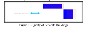
In this interpretation, ground motion occurs in the east-west direction. The structure on the left side of the diagram is east-west oriented (strong axis) and will therefore respond more tightly than other structures oriented north-south (weak axis). The way the pattern deviates also affects the difference in motion between the patterns. The stiffness of the gap between the difference in motion and the structure causes stress in the area of ??"notches" at the concave corners [13].
II. LITERATURE REVIEW
Research and comparative seismic requirements for vertically irregular and "orderly" frames determined by strict nonlinear behavioral history analysis (RHA) due to a group of Lohith gambling B C 20 ground motions. 48 inconsistencies, all with 12 floors, strong lines and weak beams, were designed with a combination of three types of inconsistency, strength and stiffness, and eight different locations along the elevation were demonstrated using two modifications.
Madan Singh et al. Observation results of vertical irregularities in storey drift and average storey displacement are recorded. Next, the mean and distribution of storey slip demand rates determined by modal thrust analysis (MPA) and nonlinear RHA are calculated to measure the deviation and distribution of the (MPA) estimates, resulting in: Although irregularities in stiffness, strength or stiffness and strength, the deviation in the MPA process does not increase, e.e. middle or top,
Mehmed Causevic et al. The study found that the MPA program was less accurate than the model used in the seismic prediction required for strong or rigid and strong front frames; soft, weak or soft under the body; Hard and strong or hard and weak. The study found that high-rise concrete walls are often supported near or below the ground by ground diaphragms attached to the perimeter foundation walls. When most of the overturning moment in the wall is transferred to the foundation wall by several or more rigid floor diaphragms, the maximum bending moment of the plastic hinge is above the diaphragm and the shear force returns to the base of the hinge. According to the rigidity of the base of the diaphragm and the shear and bending stiffness of the chest wall, the back shear under the hinge will be greater than the base shear above the hinge.
Rajiv Banerjee et al. It has been determined that the nonlinear shear model can be used to determine whether the yielding of the wall diagonal and horizontal wall reinforcement will reduce the reverse shear forces without causing shear failure. A different design solution is required as increasing the amount of horizontal reinforcement in a wall above a certain limit will not prevent shear failure. In order not to underestimate the shear stress required in high walls, upper bound estimates of soil diaphragm stiffness should be used. This study provides the latest information on the seismic behavior of vertically irregular building frames. Methods for identifying vertical irregularities under current building codes are discussed. Investigations and findings on the seismic behavior of irregular vertical structures are reviewed. It has been shown that the building code provides a method for the distribution of vertical irregularities and proposes dynamic analysis to obtain the exterior design. Most studies agree on the need for more towers for lower models and the increased seismic needs of buildings with uneven mass, stiffness and strength distribution.
Ravi Kanth et al. were analyzed and it was found that the greatest seismic demand was coupled with irregularities in stress and strength. It can be concluded that general research and building codes address the effects of vertical irregularities. The building code provides a method for the distribution of irregular vertical structures and proposes time history analysis or elastic field spectrum analysis to obtain the lateral force design. The authors are conducting a detailed study of the importance of diaphragm stiffness for the seismic response of structures. Although rigid ground diaphragms are a good assumption for seismic analysis of most buildings, some building configurations may require flexible soil diaphragms.
III. SYSTEM DEVELOPMENT
A. General
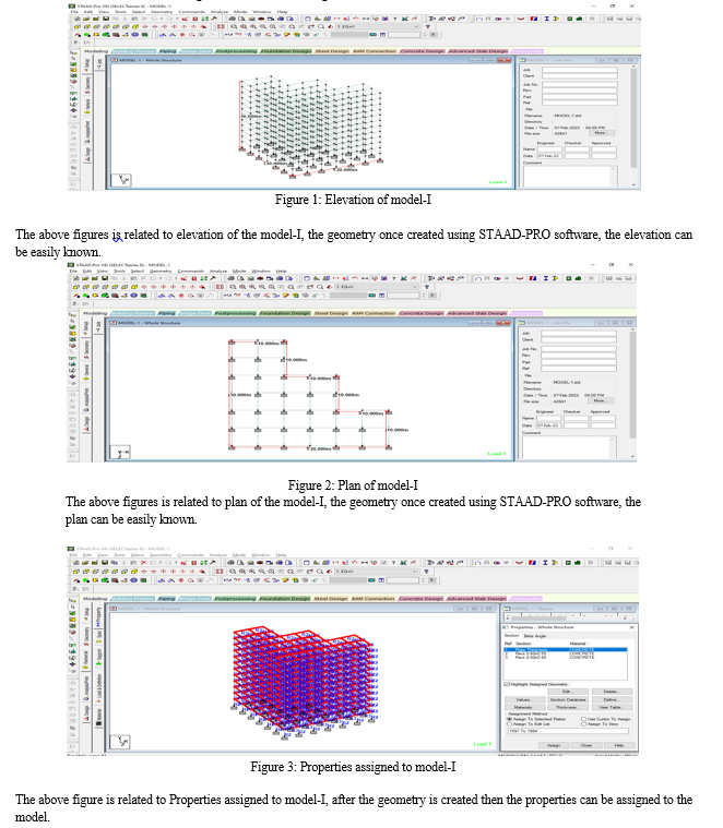
This chapter is including the method of the analysis of the building with re-entrant corners and the provision of the bracings and shear wall at different locations have been identified. The different models are modeled using STAAD-PRO as follows.
- Model-I: Multistoried Building without Shear Wall & Bracings
- Model-II: Multistoried Building with Bracings location-1
- Model-III: Multistoried Building with Shear wall location-1
- Model-IV: Multistoried Building with Shear wall - bracing location-1
- Model-V: Multistoried Building with Bracings location-2
- Model-VI: Multistoried Building with Shear wall location-2
- Model-VII: Multistoried Building with Shear wall-bracing location-2
- Model-VIII: Multistoried Building with Bracings location-3
- Model-IX: Multistoried Building with Shear wall location-3
- Model-X: Multistoried Building with Shear wall-bracings location-3
Conclusion
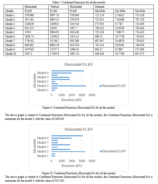
The following conclusions are drawn based on the present study. 1) In terms of combined horizontal displacement (X), Model-2 exhibits the maximum displacement with a value of 165 mm. This indicates that Model-2 experiences the highest lateral movement among all the models considered. 2) Similarly, for combined horizontal displacement (Z), Model-5 demonstrates the highest displacement of 171 mm. This suggests that Model-5 experiences significant horizontal movement in the Z-direction. 3) Moving on to combined vertical displacement (Y), Model-2 exhibits the highest displacement with a value of 21.7 mm. This indicates that Model-2 experiences the most significant vertical movement compared to the other models. 4) When considering the resultant displacement, which accounts for the combined effects in all directions, Model-5 exhibits the highest displacement of 174 mm. This implies that Model-5 experiences the most overall displacement among the analyzed models. 5) Shifting focus to the combined reactions, Model-3 displays the maximum combined horizontal reaction (Fx) with a value of 3400 kN. This suggests that Model-3 experiences the highest resistance to horizontal forces.
References
[1] Agarwal, P. and Shrikhande, M., Earthquake Resistant Design of Structures, Prentice hall of India Pvt. Ltd.,2006. [2] Ahmad J. Durrani, S.T. Mau, Amr Ahmed AbouHashish and Yi Li “EarthQuake Response of Flat-Slab Buildings” Vol.120 No. 3, March, 1994. ©ASCE,ISSN 0733-9445/94/0003-0947 [3] Akshay Nagpure1, S. S. Sanghai (2018) “Effect of Diaphragm Flexibility on the Seismic Response of RCC Framed Building Considering Diaphragm Discontinuity”, International Journal of Innovations in Engineering and Science, Vol. 3, No.5, 2018 www.ijies.net [4] Amin Alavi, P. Srinivasa Rao, Effect of Plan Irregular RC Buildings in High Sesimic Zones, Australian Journal of Basic and Applied Sciences, 7(13) November 2013, Pages: 1-6 [5] Anil K. Chopra and Chatpan Chintanapakdee “Seismic Response of Vertically Irregular Frames: Response History and Modal Pushover Analysis” Vol. 130, No. 8, August 1, 2004. ©ASCE,ISSN 0733-9445/2004/8-1177–1185 [6] Applied Technology Council (ATC 40) document, Seismic Evaluation and Retrofit of Concrete Buildings, Vol. 1, Report no. SSC 96-01, California, 1996. [7] ASCE, FEMA 356, Pre standard and commentary for seismic rehabilitation of buildings, Reston, Virginia, USA, 2000. [8] Babak Rajaee Rad and Perry Adebar “Seismic Design of High-Rise Concrete Walls: Reverse Shear due to Diaphragms below Flexural Hinge”(2009) Vol. 135, No. 8, August 1, 2009. ©ASCE, ISSN 0733-9445/2009/8-916–924 [9] Babita Elizabath baby and shreeja s (2015) “analysis of building with slab discontinuity” international journal of science and research. ISSN: 2319-7064, volume 5 issue 9, September 2016. [10] Chopra A.K., Dynamics Of Structures, 3rd edition, Prentice Hall Of India., 2007. [11] Computers and Structures, INC. CSI Analysis Reference Manual for ASP 2000, ETABS and SAFE, Berekeley, California.,2009. [12] Devesh P. Soni and Bharat B. Mistry “Qualitative Review Of Seismic Response Of Vertically Irregular Building Frames”, Vol. 43, No. 4, December 2006, pp. 121-132 [13] Dhiman Basu and Sudhir K. Jain “Seismic Analysis of Asymmetric Buildings with Flexible Floor Diaphragms”, Vol. 130, No. 8, August 1, 2004. ©ASCE, ISSN 0733-9445/2004/8-1169–1176 [14] Divyashree . M, Gopi siddappa, Seismic Behaviour Of RC Buildings With Re-Entrant Corners And Strengthening, IOSR Journal Of Mechanical And Civil Engineering., pg – 63 to 69. [15] Dubey, S.K and Sangamnerkar., Seismic Behaviour of Asymmetric Rc Buildings., International journal of advanced engineering technology, 2(4): 296-301., 2011. [16] Eduardo Miranda and Carlos J. Reyes “Approximate Lateral Drift Demands in Multistory Buildings with Non uniform Stiffness” Vol. 128, No. 7, July 1, 2002. ©ASCE, ISSN 0733-9445/2002/7-840–849 [17] ETABS Nonlinear v9.6, Extended Three-dimensional Analysis of Building Systems, Computers and Structures Inc., Berkeley, California, USA, 1995. [18] IS- 1893- Part I: 2002, Criteria for Earthquake Resistant Design of Structures,Bureau of Indian Standards, New Delhi. [19] IS: 456-2000, “Code of Practice for Plain and Reinforced Concrete”, Bureau of Indian Standards, New Delhi, India. [20] IS:1893-2002(Part 1) Criteria for Earthquake Resistant Design of Structures, part 1-General provisions and buildings, fifth revision, Bureau of Indian Standards, New Delhi, India [21] Kazi Muhammed mustaqeem and md mansoor ahmad (2016) “impact of intermittent diaphragm and re-entrant corners on seismic response of multistoried RC framed buildings” international journal of engineering research and technology. ISSN: 2278-0181, vol. 5 issue 07, July-2016 [22] Komal R. Bele1, S. B. Borghate (2015) “Dynamic Analysis of Building with Plan Irregularity”, Journal of Civil Engineering and Environmental Technology, ISSN: 2349-8404, Volume 2, April – June, 2015
Copyright
Copyright © 2023 Shruti Diliprao Raut, Prof. Vishal Sapate. This is an open access article distributed under the Creative Commons Attribution License, which permits unrestricted use, distribution, and reproduction in any medium, provided the original work is properly cited.

Download Paper
Paper Id : IJRASET54933
Publish Date : 2023-07-23
ISSN : 2321-9653
Publisher Name : IJRASET
DOI Link : Click Here
 Submit Paper Online

