Ijraset Journal For Research in Applied Science and Engineering Technology
- Home / Ijraset
- On This Page
- Abstract
- Introduction
- Conclusion
- References
- Copyright
Comprehensive CFD Analysis of Hypersonic Missile Nose Cone
Authors: Sahil Mathur, Rahul Singh
DOI Link: https://doi.org/10.22214/ijraset.2024.65672
Certificate: View Certificate
Abstract
This study employs high-fidelity CFD to analyze a hypersonic missile nose cone\'s aerodynamics and boundary layer behavior (Mach > 5, zero angles of attack) under idealized conditions. The simulation leverages ideal gas assumptions for simplicity while incorporating advanced turbulence models to capture hypersonic flow phenomena. The analysis focuses on pressure distribution across the nose cone to assess shockwave and streamline curvature effects. Lift and drag forces are computed to evaluate overall aerodynamic performance. Critically, the investigation delves into the boundary layer, evaluating parameters like thickness, velocity profile, and potential separation points to understand pressure and temperature variations crucial for heat transfer and flow stability.
Introduction
I. INTRODUCTION
The Computational Fluid Dynamics (CFD) analysis of the nose of a hypersonic missile is a pivotal research area. It sheds light on the profound effects of pressure, density, and temperature on the rocket's nose cone [1]. When an object travels at supersonic speed, it generates shockwaves. These shockwaves are produced because the object is moving faster than the speed of sound [2]. If the object is a hypersonic body, the distance between the object and the shockwave can be relatively small [3]. We refer to the flow field between the object and the shockwave as the shock layer in such cases. The shock layer is a region of compressed air where the air molecules move so quickly that they become heated and ionized. This shock layer can be fragile for hypersonic speeds, which poses unique challenges for designing hypersonic vehicles and understanding their behavior [4]. As a hypersonic vehicle travels through the earth's atmosphere, it experiences immense frictional forces that generate tremendous heat [5]. This heat is so intense that it can cause the molecules within the air to vibrate vigorously and even break apart into smaller parts or ionize [6]. In addition, if the vehicle has an ablative heat shield, the materials that burn and peel away from it can also mix with the air and cause complex chemical reactions. These reactions can create a layer of moisture on the surface of the vehicle, which can cause it to become slippery and difficult to control [7]. Therefore, it is crucial to consider these factors when designing and developing hypersonic vehicles to ensure their safe and effective operation [8].
The study reveals how pressure and temperature influence the boundary layer as the object moves at hypersonic speed, producing a low shockwave known as Bow shock, as demonstrated in the analysis of the nose cone. The research delves into various aspects of the flow field. The pressure distribution across the nose cone surface is meticulously examined to understand the impact of shockwaves and streamline curvature. Lift and drag forces acting on the nose cone are computed to comprehensively assess its overall aerodynamic performance. Notably, the investigation focuses on the characteristics of the boundary layer – the thin region of viscous flow adjacent to the nose cone. Parameters such as boundary layer thickness, velocity profile, and potential separation points are evaluated to understand the crucial aspects of heat transfer and stability of the flow.
This CFD analysis offers valuable insights into the aerodynamics of the nose cone under ideal conditions. The study validates the CFD methodology by establishing a baseline for ideal flow behavior. More importantly, it is a robust foundation for future investigations incorporating real-gas effects, heat transfer analysis, and the influence of environmental variations like temperature and altitude.
II. HYPERSONIC AERODYNAMICS
The spiked nose cone is used in the analysis of a hypersonic missile; previously, the curved or parabolic nose cone was used for the missile, but the flow separation occurred more rapidly in the parabolic nose cone as compared to the spiked nose cone. The flow is attached to the nose cone at high speed, while the flow is separated in the parabolic nose cone.
A. Equations
The isentropic relations of pressure and temperature for the compressible hypersonic flow before entering the supersonic region and after entering the supersonic region are given,
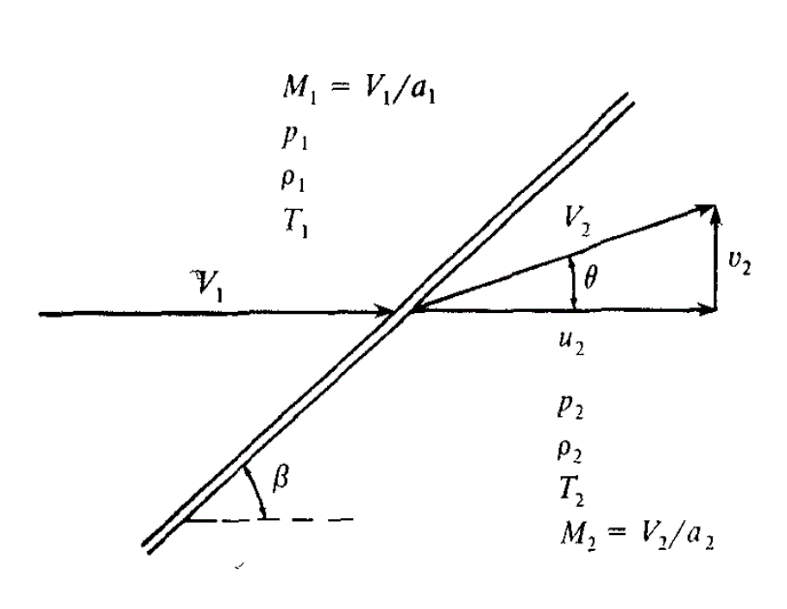
Fig.1 Oblique Shock wave Geometry [9]
The hypersonic limit of the pressure, temperature, and density with respect to the Mach number are given by,
p2p1=2γγ+1 M12sin2β
ρ2ρ1=γ+1γ-1
T2T1=2γγ-1γ+12M12sin2β
u2V1=1-(2sin2β)1γ+1
v2V1=sin2βγ+1
Cp=4γ+1sin2β 
For the pressure across the wave is given by the equation,
p2p1=1+2γγ+1(M12sin2β-1)
ρ2ρ1=γ+1γ-1
T2T1=2γγ-1γ+12M12sin2β
Were,
γ=CpCv
The above equations give the pressure, temperature, and density ratio values at the hypersonic speed [9]. Fig. 1 shows oblique shock wave geometry.
III. METHODOLOGY
The missile's nose cone was designed using Space Claim design in Ansys Software. Symmetry was used to create the rocket's nose cone. The design of the missile's nose cone is represented in Fig. 2.
A. Design Considerations:

Fig.2 Design of the nose cone of the Missile
Aerodynamics:
- Shockwave mitigation: The nose cone shape is crucial in managing shockwaves that form at hypersonic speeds (Mach 5+). Ideally, the design should minimize the intensity of the bow shockwave to reduce drag and improve overall aerodynamic performance. This can be achieved through specific cone angles and blunted shapes.
- Lift and drag balance: While minimizing drag is essential, some lift generation might be desirable for manoeuvrability. Depending on the specific missile application, the nose cone shape must be optimized to achieve the desired balance between lift and drag.
- Stability: The design should ensure the nose cone maintains stability during flight. This involves considering factors like the centre of pressure and ensuring the design avoids flow separation that could lead to control issues.
B. Thermal Management
- Heat transfer: Hypersonic speeds generate extreme heat due to air friction. The nose cone material and design need to handle this heat effectively. This might involve using heat-resistant materials or incorporating features that promote heat dissipation.
- Bluntness: Blunt nose cones can help absorb heat generated by the shockwave, reducing the thermal load on the rest of the missile. However, this needs to be balanced against aerodynamic considerations.
C. Other factors
- Weight: The nose cone should be lightweight to maximize overall missile performance. Material selection and design optimization are crucial in achieving this.
- Radar Cross Section (RCS): Minimizing the nose cone's radar signature is essential for stealthy missiles. Specific shapes and radar-absorbent materials can be employed to achieve low RCS.
- Manufacturing complexity: The design should be manufacturable using available techniques to ensure cost-effectiveness and production feasibility.
D. Meshing
- Element size: The elements near the nose cone surface (boundary layer) should be outstanding in capturing the complex flow behaviour in this region. The element size can gradually increase as you move away from the surface. Fig 3 shows a 2D mesh of the nose cone.
- Aspect ratio: Elements should be as close as possible to square or equilateral triangles for better accuracy. Avoid highly elongated or skewed elements.
- Smoothness: Transitions between elements should be smooth, especially near sharp corners or curvature changes, to avoid introducing numerical errors.
. 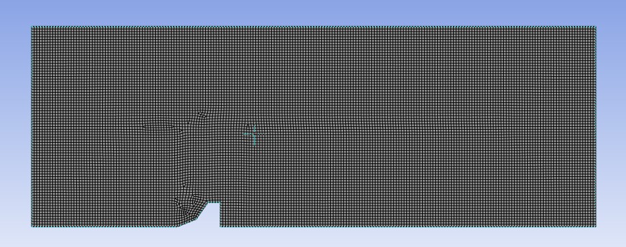
Fig 3. 2D mesh of the nose cone
The mesh should be very fine near the edge of the body. A far field should also be created around the body to mimic an experimental setup. The far-field should have a very fine quadrilateral mesh to ensure accurate results. The minimum orthogonal quality of the mesh should be 0.8161, and the maximum aspect ratio should be 1.4. A five-layer boundary layer with a growth ratio 1.2 should be implemented, with the first element size set at 130 mm. Table 1. provides information about mesh element size, mesh nodes, and number of elements.
Table 1. Grid Independence Test of Nose cone of missile
|
Mesh Element Size (mm) |
Mesh nodes |
Mesh Elements |
|
130 |
16512 |
16217 |
|
100 |
27865 |
27479 |
|
70 |
56791 |
56242 |
|
50 |
110543 |
109776 |
It is well known that the mesh quality and arrangement are critical factors when simulating flow around a body. Near the shock wave, the grid should be refined to capture the flow gradients accurately. The body's surface should be meshed very finely near tiny faces compared to larger ones.
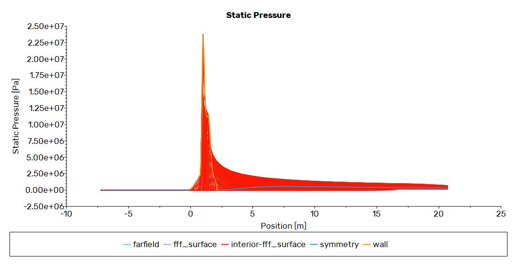
Fig. 4. Pressure plot
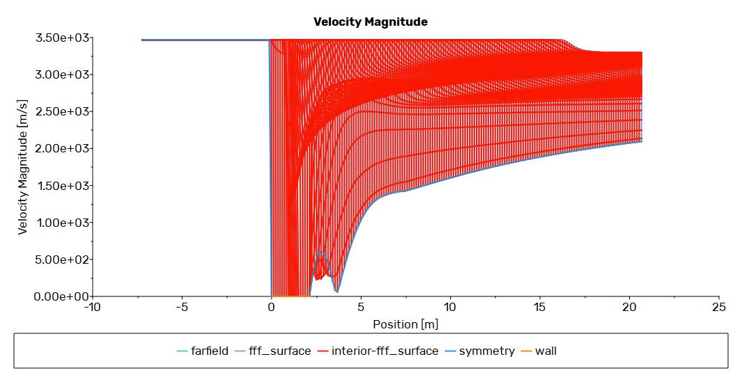
Fig. 5. Velocity Plot
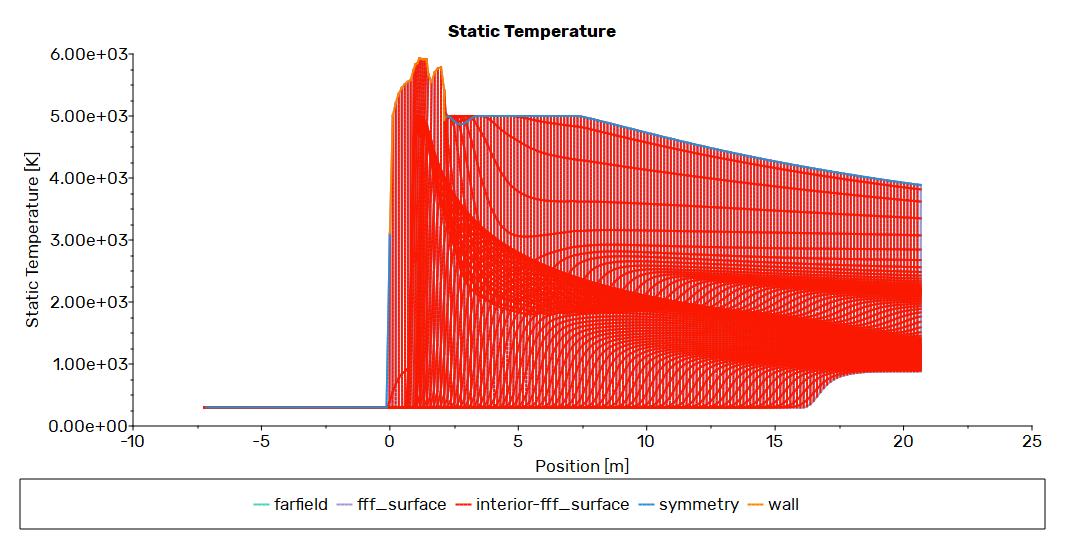
Fig. 6. Static Temperature Plot
IV. RESULTS AND DISCUSSION
The fluid flow analysis of the hypersonic missile is carried out in actual atmospheric conditions. The vehicle creates a bow shock and boundary layer, followed by flow separation on the afterbody during the simulation. The pressure graph shown in Fig. 4 states that initially, the pressure at the nose cone at the spike section increases rapidly, and afterward, the pressure starts dropping as the flow reaches the end of the nose cone. At last, the pressure becomes nearly constant. Fig. 5 shows the velocity distribution of the two-dimensional model at Mach number = 10. During the cruise phase, the missile's angle of attack is zero, and the bow is created during the transition from the subsonic to the supersonic region. Fig. 6 shows the temperature contour and distribution along the missile's boundary layer, varying from 300 K to 5000 K. Similarly, the thing happened with the temperature: the temperature starts to rise rapidly at an alarming rate, but as the flow reaches the middle and the end of the nose cone, the temperature begins to decrease as the flow moves along. The opposite thing happened with the velocity magnitude, as it increases rapidly and goes on increasing until it reaches the maximum velocity.
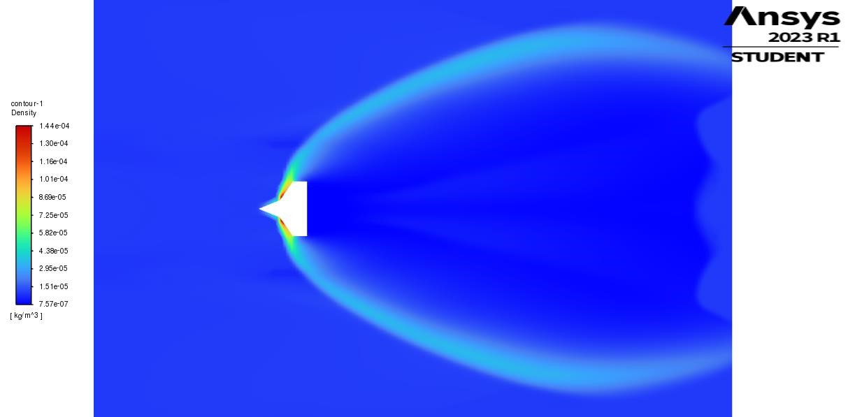 Fig. 7 Density Contour
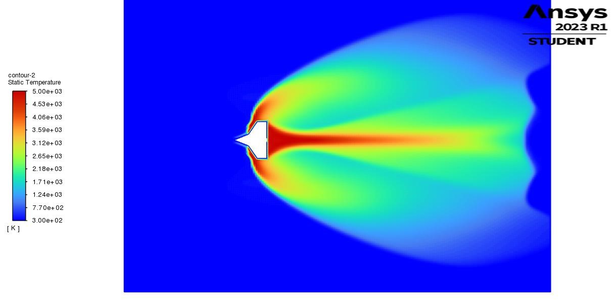 Fig. 8. Static Temperature plot
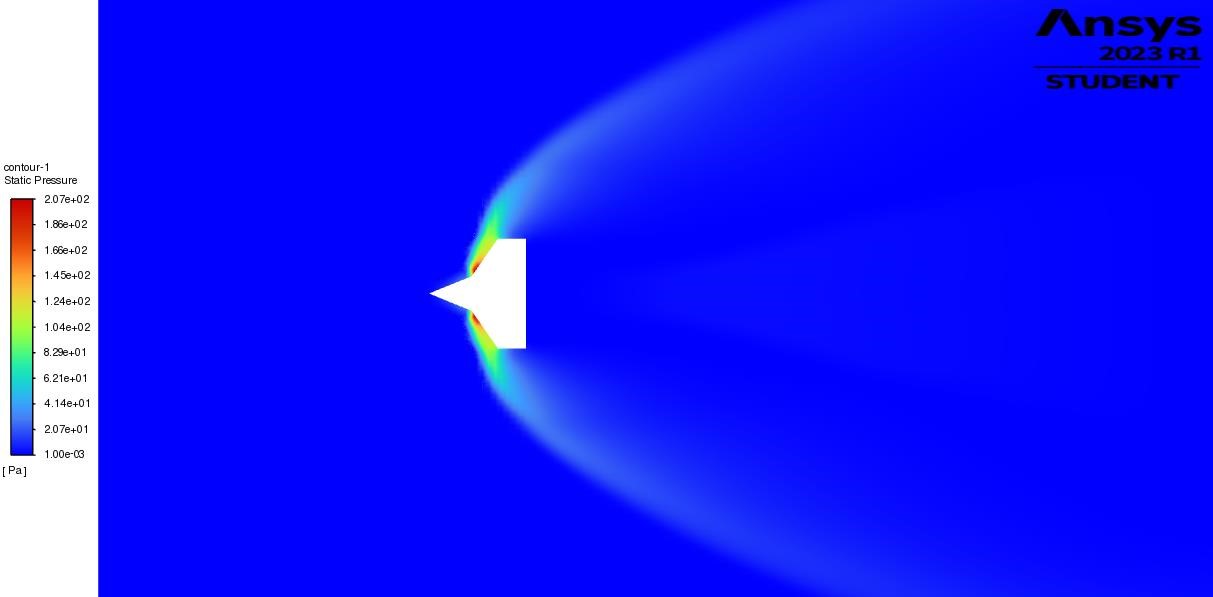
Fig. 9 Pressure Contour
Figs. 7-9 shows the Bow Shockwave's temperature, density, and pressure contour from the missile when it transitions from the subsonic to the supersonic region. The maximum pressure is exerted behind the missile's edge and gradually decreases with the shockwave. The missile's Mach number gradually increases as it moves forward, showing it is moving at a hypersonic speed. This can be observed from Fig. 10.
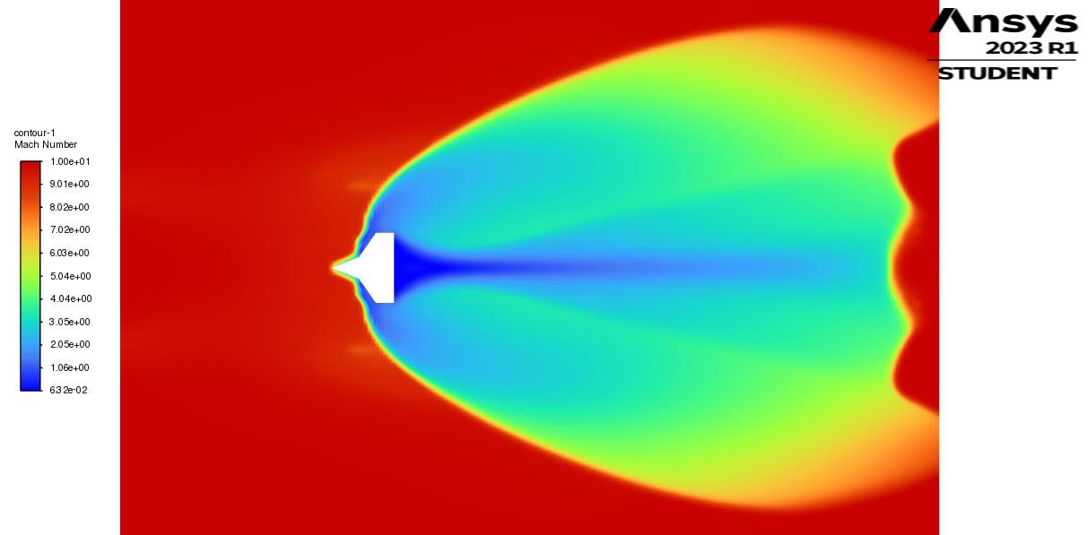 Fig. 10 Mach Contour
Conclusion
This work carries out CFD analysis of hypersonic missile nose cones. The solution of the above analysis is converged, and the Density-based implicit is used. A strong bow shock wave dominates the forebody flow field. This CFD analysis establishes a baseline for ideal flow behavior, validating the methodology for future investigations incorporating real-gas effects, heat transfer analysis, and the influence of environmental variations. This comprehensive approach paves the way for optimizing hypersonic missile nose cone design for superior performance across diverse operating conditions.
References
[1] Mirmirani, M., Wu, C., Clark, A., Choi, S. and Fidan, B., 2005, June. Airbreathing hypersonic flight vehicle modelling and control, review, challenges, and a CFD-based example. In Proc. Workshop on Modeling and Control of Complex Systems, Ayia Napa, Cyprus. [2] Tracy, C.L. and Wright, D., 2020. Modelling the performance of hypersonic boost-glide missiles. Science & Global Security, 28(3), pp.135-170. [3] Starkey, R., Liu, D., Baldelli, D., Chang, R. and Chen, P., 2008, April. Rapid conceptual design and analysis of a hypersonic air-breathing missile. In 15th AIAA international space planes and hypersonic systems and technologies conference (p. 2590). [4] Viti, V., Rao, V. and Abanto, J., 2020. CFD simulations of super/hypersonic missiles: validation, sensitivity analysis, and improved design. In AIAA Scitech 2020 Forum (p. 2123). [5] Zhang, C.A., Ye, Z.Y. and Zhang, W.W., 2007, January. Aeroservoelastic analysis for supersonic and hypersonic missiles. In 45th AIAA Aerospace Sciences Meeting and Exhibit (p. 1073). [6] Srivastava, B., 1996. CFD analysis and validation of lateral jet control of a missile. In 34th Aerospace Sciences Meeting and Exhibit (p. 288). [7] Viviani, A., Aprovitola, A., Pezzella, G., Rainone, C., 2021, CFD design capabilities for next generation high-speed aircraft. In Acta Astronautica. [8] Nielsen, J.E., Diskin, B., 2017, High-Performance Aerodynamic Computations for Aerospace Applications. Parallel Computing. [9] Anderson, J.D., 1990. Modern Compressible Flow with Historical Perspective. ISBN 0-07-100665-6.
Copyright
Copyright © 2024 Sahil Mathur, Rahul Singh. This is an open access article distributed under the Creative Commons Attribution License, which permits unrestricted use, distribution, and reproduction in any medium, provided the original work is properly cited.

Download Paper
Paper Id : IJRASET65672
Publish Date : 2024-11-29
ISSN : 2321-9653
Publisher Name : IJRASET
DOI Link : Click Here
 Submit Paper Online

