Ijraset Journal For Research in Applied Science and Engineering Technology
- Home / Ijraset
- On This Page
- Abstract
- Introduction
- Conclusion
- References
- Copyright
Design and Construction of 3 DOF Prototype Delta Parallel Robot
Authors: Theodor Myklebusthaug, Ali Zilouchian
DOI Link: https://doi.org/10.22214/ijraset.2024.62280
Certificate: View Certificate
Abstract
The design and construction of a prototype delta robot to utilize for upper secondary educational institutes is presented. The focus is on leveraging 3D printing technology in AutoCAD for component fabrication, detailing electrical schematics, and integrating Arduino for its intuitive User Interface (UI). The project’s objective is to construct a delta robot prototype equipped with essential features to serve as an educational tool for teaching fundamental robotics principles. Additionally, the design allows for customization of specific robot parts in future iterations to adapt it to various applications as needed.
Introduction
I. INTRODUCTION
A. Overview
Today the manufacturing industry is evolving rapidly, heavily around the automatization of manufacturing processes that require high performance and low cost. Due to the low moment of inertia of the end effector, the delta robot can achieve high-speed movement and while retaining high precision. Resulting in being a highly desired robot in the food, electrical, and pharmaceutical industry where fast pick-and-place is required [1]. Therefore, this project is designed to be used as a learning tool exploiting the bright future of the robotics industry. The robot will mainly be designed from 3D printed parts in polylactic acid (PLA) plastic, designed in AutoCAD software. The selected open-source single-board microcontroller is an Arduino Uno R3. A highly versatile open-source microcontroller that allows for the connection of external accessories and includes an easy-to-use Integrated Development Environment (IDE) [2]. It is in the IDE the user will be able to access the User Interface (UI) and manipulate the movement of the robot. This includes being able to set up an automated trajectory, with speed and time control, and a mode where coordinates can be inputted through the UI, and calibration of the robot. A series of questions will be asked in the serial monitor located in the IDE, which will allow the user to make their input and program the robot. In sequel, the Arduino will send the information to a driver controlling the position of the stepper motor. A gripper will be mounted to the moving platform as the end effector, powered by a 5g servo motor. Implementing the inverse kinematics of the robot in the Arduino code will allow the user to input the desired coordinate of the end effector down to millimeter precision. This will allow the user to explore robotics concepts such as work envelope, maxima speed, sensory feedback, and computer system for control.
B. Motivation for Design
This project evolved as part of a Senior Design Project, reflecting the lead author's keen interest in robotics and career aspirations. Through designing and building a robot, the lead author gained insights into delta robots' challenges and potentials, fostering a deeper appreciation for the diverse opportunities within the robotics field. This hands-on experience provided valuable exposure to practical complexities while laying a solid groundwork for future pursuits in robotics.
???????C. Objectives
The objective for this project was to firstly design and construct a functioning 3DOF delta robot, while gaining and applying knowledge to produce a best possible product. Secondly, to allow for customizability of the robot by taking use of 3D printing technology, in a manner that opens up the possibility to make the robot fit any desired application.
II. KINEMATIC DESIGN
A. 3 DOF Delta Robot
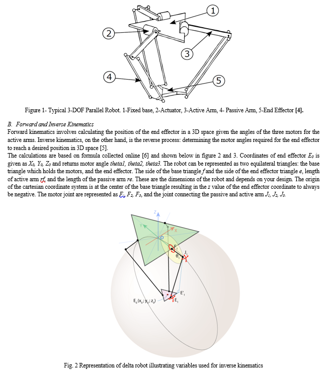
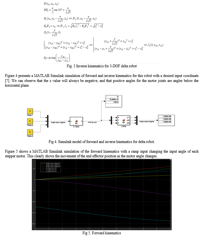
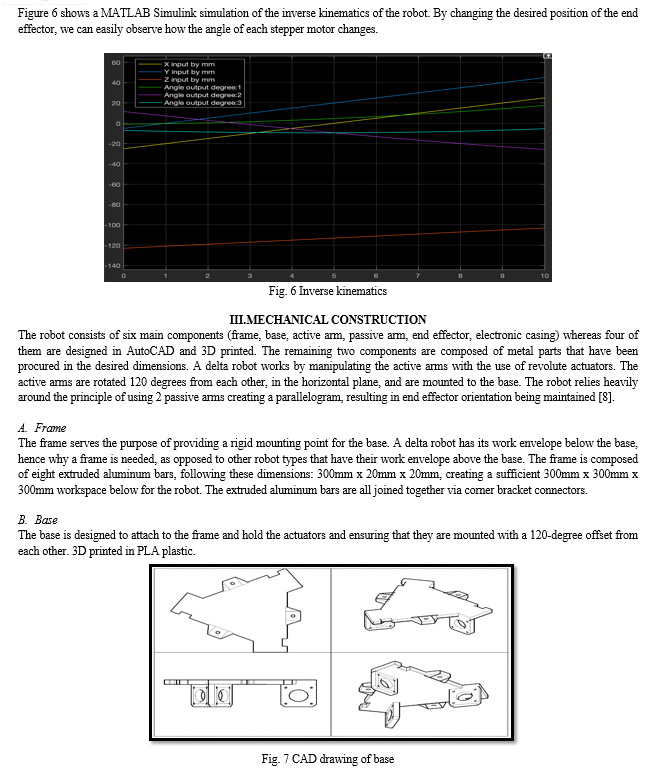
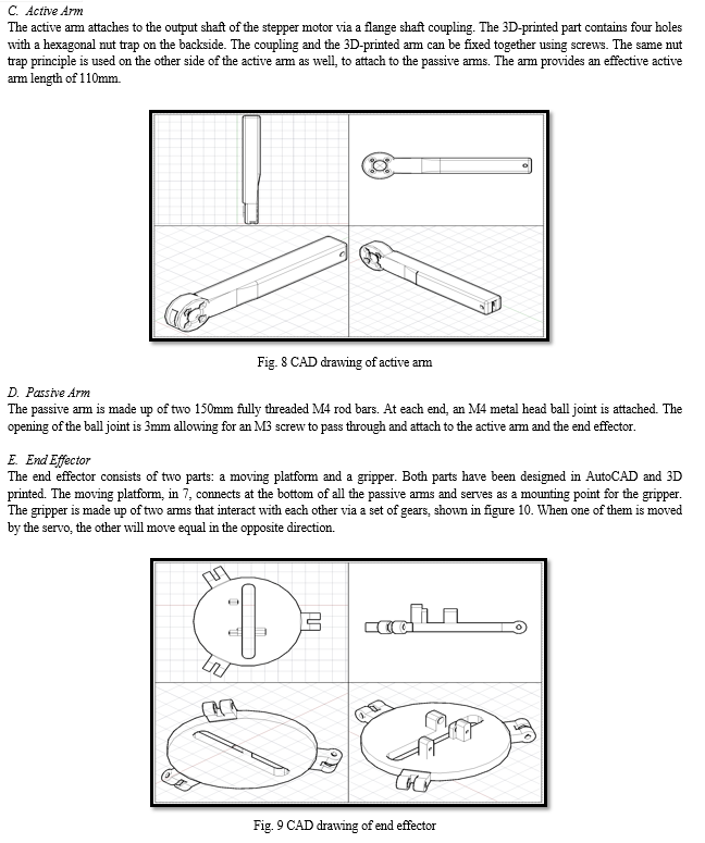
Parallel robots with 3 degrees of freedom consist of a base and an end effector linked together by three open kinematics chains. In a Delta parallel robot, the three identical open kinematics chains are powered by one rotary actuator each. Connecting the end effector with two links creates a parallelogram and locks the orientation horizontal at all times [3].
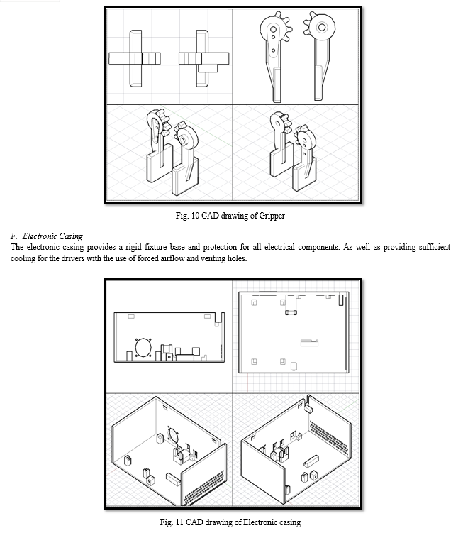
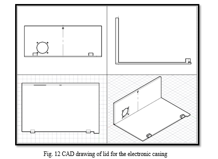
IV. ELECTRICAL AND CONTROL SYSTEM
A. Arduino
Arduino is a versatile open-source platform built around the ATmega328P microcontroller, offering a wide array of features and capabilities for electronics projects. The board boasts 6 analog input pins and 14 digital input/output pins, with 6 of them supporting Pulse Width Modulation (PWM) functionality, providing users with extensive flexibility for interfacing with sensors, actuators, and other peripheral devices [2]. Operating at a voltage of 5 volts, the ATmega328P microcontroller is renowned for its reliability and efficiency in handling a variety of tasks.
One notable feature of the ATmega328P microcontroller is its 1 KB Electrically Erasable Programmable Read-Only Memory (EEPROM), which allows it to retain stored information even when power is removed, owing to its non-volatile properties [9]. This capability ensures that crucial data or program settings are preserved across power cycles, enhancing the reliability and stability of Arduino-based projects.
Programming Arduino is facilitated through an intuitive development environment that is derived from the C++ programming language. This environment simplifies the process of writing and uploading code to the Arduino board, making it accessible to both beginners and experienced developers alike. Additionally, Arduino's vast online community provides a wealth of resources, tutorials, and libraries, further easing the learning curve and enabling users to quickly bring their ideas to fruition.
???????B. Nema 17 HE15-1504S
The Nema 17 stepper motor, renowned for its reliability and performance, exhibits specific electrical characteristics crucial for its operation. With a coil current rating of 1.5 Amperes and an internal resistance of 2.3 Ohms, it is optimized to deliver consistent and efficient power distribution [10]. To ensure reliable operation and accommodate potential fluctuations in power requirements, a 45-watt Power Supply Unit (PSU) is deemed sufficient, incorporating a 50 percent safety margin within the 12-24v range.
Beyond its electrical specifications, the stepper motor's mechanical capabilities contribute significantly to its functionality. In its base configuration, the motor offers 200 steps per revolution, providing a foundational level of precision for various applications. However, by leveraging the micro-step function, users can achieve finer granularity in motion control. Enabling a 1/16th step increases the steps per revolution to an impressive 3200, significantly enhancing the motor's precision and resolution.
The implementation of micro-stepping allows for a reduction in the motor's step angle to 0.1125 degrees, thereby augmenting the robot's ability to execute intricate movements with utmost accuracy. This substantial increase in resolution translates to a remarkable improvement in positioning precision, reducing the margin of error from +/- 2.81mm to an exceptional +/- 0.17mm.
Despite the evident benefits of micro-stepping in enhancing precision, it is essential to acknowledge the trade-offs involved. One notable drawback is the considerable loss of holding torque, amounting to approximately 90% in this configuration [11]. While this reduction in torque may pose limitations in certain applications requiring high holding torque, the significant gains in precision and resolution render micro-stepping a compelling choice for tasks prioritizing accuracy.
???????C. Driver
The A4988 IC driver stands out for its advanced features, including variable current limitation and built-in protection against overheating. With a maximum current output of two amperes per coil with additional cooling, and one ampere without cooling, it ensures versatility in various operating conditions. For this project, the current limiter will be adjusted to 1.5 amperes to optimize performance, necessitating the addition of a heat sink, and forced airflow to the driver [12]. In the context of this project, the integration of micro-stepping technology offers enhanced precision and control, contributing to the overall success and effectiveness of the robotic system.
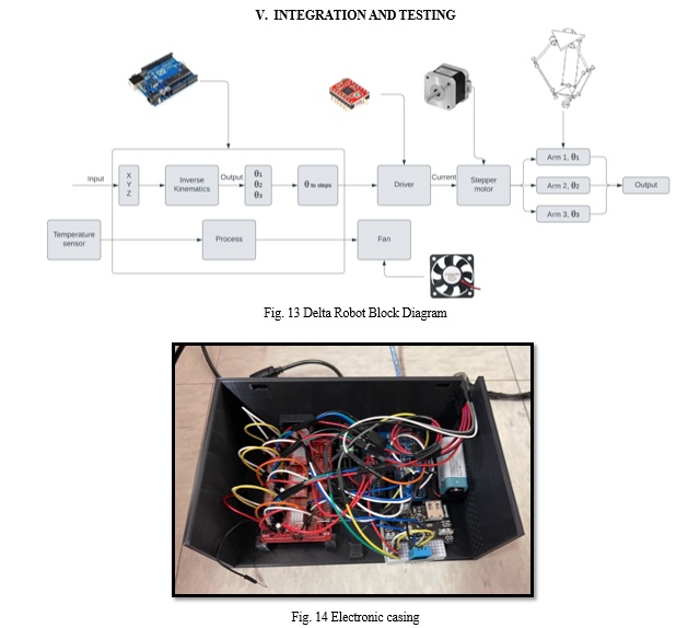
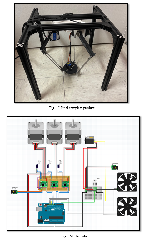
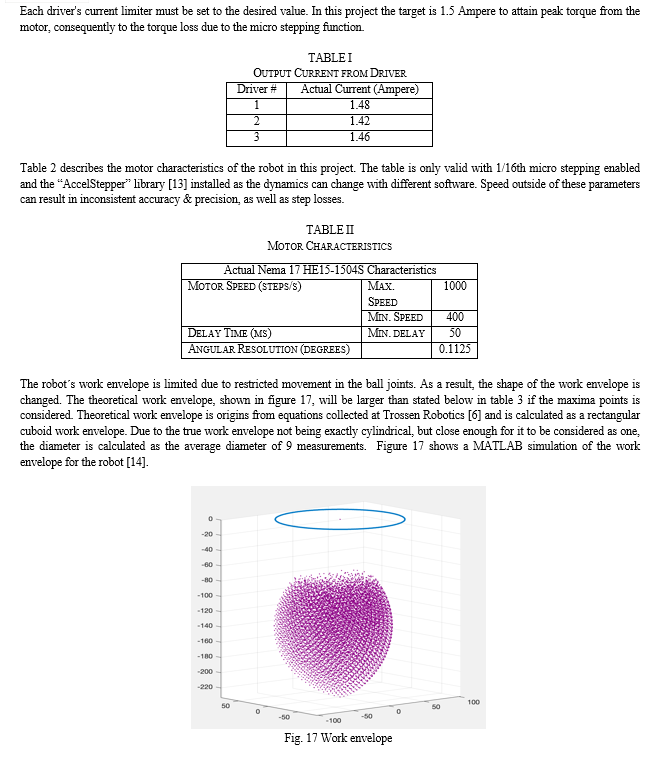
TABLE III
Robot Characteristics
|
Robot Dimensions (mm) |
Base radius (f) |
70 |
|
End effector radius (e) |
98 |
|
|
Active arm (rf) |
110 |
|
|
Passive arm (re) |
160 |
|
|
Work envelope (mm) |
Theoretical (rectangular cuboid) (x, y, z) |
145.8 x 145.8 x146 |
|
Actual (cylinder) (d, h) |
139.7 x 101 |
|
|
Resolution (mm) |
|
+/- 0.17 |
VI. CHALLENGES AND SOLUTIONS
A servo motor was initially settled on for this project, due to its easy position control and high torque. However, a major drawback with the servo motor was the lack of speed control and angular resolution, resulting in poor control of the end effector [15]. Therefore, a stepper motor was decided on to replace the servo motor with its microstep function and speed control. The downside is the huge lack of torque, but due to the light weight of the end effector, the torque offered from the stepper motor will still be sufficient for this application.
A core principle that was considered during this project was Design for Manufacturability (DFM). Because 3D printing works by printing layer by layer, a vertical hole results in the printer having to print an overhang. This means that it will print over the edge of the layer below and into free air. IN certain instances when this overhang becomes too large, the hole loses its dimensions. A solution to this is to shape the holes into water droplets to reduce the overhang [16], as well as carefully considering the orientation of the product during the printing process. I experienced some shrinkage of the parts, meaning that the finished product tended to be slightly smaller than in the design, consequently I would have to design every dimension slightly larger to account for this shrinkage.
VII. ACKNOWLEDGEMENT
The lead author wishes to extend gratitude to Dr. Ali Zilouchian, Director of the Applied Engineering Research Center and Program Director, for his invaluable assistance, guidance, and support throughout the project endeavor. Additionally, thanks are extended to Prof. Tim Shoushounova for his encouragement, support, and invaluable guidance in CAD. Lastly, heartfelt appreciation is expressed for the support received from friends and family.
Conclusion
In conclusion, the robot operates effectively without any significant flaws or limitations. Its adaptable design facilitates effortless modification and reconfiguration to suit diverse applications. Fulfilling the primary objective of the project, the robot serves as a valuable educational tool for students to explore robotics concepts. The user-friendly interface facilitates hands-on learning of robot programming. Moreover, the robot\'s components are highly customizable, empowering students to design and integrate their own modifications. This flexibility enables adjustments to the work envelope, precision, speed, and end effector, fostering creativity and innovation in robotics education.
References
[1] KUKA. (n.d.). KR DELTA Roboter. Retrieved from https://www.kuka.com/en-us/products/robotics-systems/industrial-robots/kr-delta-roboter [2] Arduino, \"Arduino Uno Rev3,\" Arduino. [Online]. Available: https://store-usa.arduino.cc/products/arduino-uno-rev3?_gl=1*1f9xf14*_ga*ODc5MzI3NDg4LjE3MTE5OTQ3NDY.*_ga_NEXN8H46L5*MTcxMjI2MzE5NS42LjEuMTcxMjI2NjQ1Ny4wLjAuMzE1NTMzMzA5*_fplc*aGs1a09NZGREUk0yNW5FUVE3cVFERndTcGgzOEclMkI0V3czZm9QNUJrWGJ6YjZ3aGk5MUlqNFNXRjc0MTJ6dTd6RkphYkxJZFJGMlFBcW5WZmlxVWZVSGFwc29ja25COXpiMjgyaDQzSmRHM1BIU20wdDVQJTJCSnp2YnNqTzVUQSUzRCUzRA..&selectedStore=us [3] S. -D. Stan, M. Manic, C. Szep and R. Balan, \"Performance analysis of 3 DOF Delta parallel robot,\" 2011 4th International Conference on Human System Interactions, HSI 2011, Yokohama, Japan, 2011, pp. 215-220, doi: 10.1109/HSI.2011.5937369. keywords: {Parallel robots;Indexes;Kinematics;Jacobian matrices;Mathematical model;Manipulators;performance analysis;Delta parallel robot;3DOF;workspace;kinematics}, [4] Saied, Hussein & Chemori, Ahmed & Bouri, Mohamed & El Rafei, Maher & Clovis, Francis & Pierrot, François. (2019). A New Time-Varying Feedback RISE Control for 2nd-Order Nonlinear MIMO Systems: Theory and Experiments. International Journal of Control. 94. 10.1080/00207179.2019.1704063. [5] Hadfield. H., Wei. L., and Lasenby. J, “The Forward and Inverse Kinematics of a Delta Robot”, University of Cambridge, 2020, Retrieved from https://api.repository.cam.ac.uk/server/api/core/bitstreams/4787fb8e-9639-4421-bb8e-09314a613aae/content [6] A. Nikanorov, \"Delta robot tutorial,\" Hypertriangle. [Online]. Available: https://hypertriangle.com/~alex/delta-robot-tutorial/. [7] Hasan Zabihifar (2024). Kinematic Delta Robot (https://www.mathworks.com/matlabcentral/fileexchange/63877-kinematic-delta-robot), MATLAB Central File Exchange. Retrieved May 2, 2024. [8] Acrome. (n.d.). What Are Delta Robots Used For? Retrieved from https://acrome.net/post/what-are-delta-robots-used-for#:~:text=Most%20delta%20robots%20consist%20of,connecting%20rods%20organized%20in%20parallelograms. [9] Microchip. (n.d.). ATmega328P Microcontroller. Retrieved from https://www.microchip.com/en-us/product/atmega328p# [10] OMC Stepper Online. (n.d.). E-Series NEMA 17 Bipolar 42Ncm (59.49oz.in) 1.5A 42x42x38mm 4 Wires w/ 1m Cable & Connector. Retrieved from https://www.omc-stepperonline.com/e-series-nema-17-bipolar-42ncm-59-49oz-in-1-5a-42x42x38mm-4-wires-w-1m-cable-connector-17he15-1504s [11] Faulhaber Group, \"Stepper motor tutorial - Microstepping: Myths and realities,\" Faulhaber Group. [Online]. Available: https://www.faulhaber.com/en/know-how/tutorials/stepper-motor-tutorial-microstepping-myths-and-realities/. [Accessed: Apr. 4, 2024]. [12] Pololu Corporation, \"Pololu - DRV8825 Stepper Motor Driver Carrier, High Current,\" Pololu Corporation. [Online]. Available: https://www.pololu.com/product/1182. [13] M. McCauley, \"AccelStepper class reference,\" AirSpayce. [Online]. Available: https://www.airspayce.com/mikem/arduino/AccelStepper/classAccelStepper.html. [14] Yuliya Smirnova (2024). Delta-robot kinematic (https://www.mathworks.com/matlabcentral/fileexchange/71119-delta-robot-kinematic), MATLAB Central File Exchange. Retrieved May 2, 2024. [15] AMCI. (n.d.). Stepper vs. Servo. Retrieved from https://www.amci.com/industrial-automation-resources/plc-automation-tutorials/stepper-vs-servo/#:~:text=At%20high%20speeds%20the%20stepper,throughout%20the%20entire%20speed%20range. [16] Pollen. (n.d.). Design for 3D Printing: Holes. Retrieved from https://www.pollen.am/design_for_3d_printing_holes/
Copyright
Copyright © 2024 Theodor Myklebusthaug, Ali Zilouchian. This is an open access article distributed under the Creative Commons Attribution License, which permits unrestricted use, distribution, and reproduction in any medium, provided the original work is properly cited.

Download Paper
Paper Id : IJRASET62280
Publish Date : 2024-05-17
ISSN : 2321-9653
Publisher Name : IJRASET
DOI Link : Click Here
 Submit Paper Online

