Ijraset Journal For Research in Applied Science and Engineering Technology
- Home / Ijraset
- On This Page
- Abstract
- Introduction
- Conclusion
- References
- Copyright
Controlling of Solar Based Electric Vehicle Charging Station Through Intelligence Controller for G2V and V2G Modes
Authors: Banoth Balavidyasri , Dr. JBV. Subrahmanyam
DOI Link: https://doi.org/10.22214/ijraset.2024.63921
Certificate: View Certificate
Abstract
Solar based electric vehicle (EV) charging station was proposed in this paper. The maximum power of a PV module varies due to changing temperature, solar radiation, and load. In order to extract the Maximum power point in this work, an MPPT system consisting of a PV module, a DC-DC converter, and a fuzzy logic controller is designed and simulated in Simulink. The EV battery SOC characteristic is observed to be fully charged within short period. In this paper single Phase grid and the PV system with the Fuzzy controller MPPT is connected to the DC link, which is connected to the EV. Also in the absence of solar PV energy, electric vehicle is charged from the grid. A battery of rating 100AH is charged with the solar PV panel using a boost converter which generates output voltage of 400V. Then the voltage is stepped down for buck operation according to 220 V battery requirement. A Bidirectional AC-DC rectifier is connected to the Grid, and the DC-DC boost converter for the MPPT and the DC-DC bidirectional Converter is connected to the EV for the Charging and Discharging of the EV. During charging and discharging modes the battery voltage and current is presented. It is clear that the grid voltage and current are in phase during charging. During discharging they are said to be out of phase indicating the reverse power flow.
Introduction
I. INTRODUCTION
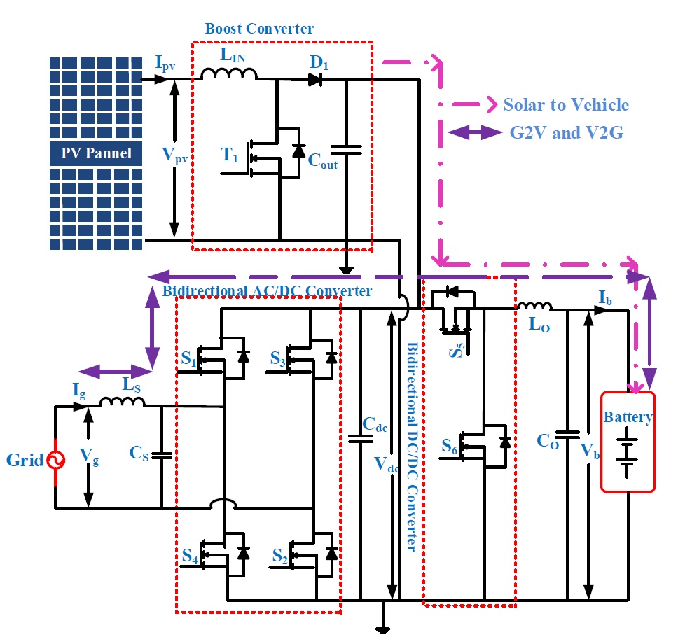
In day to day life increasing of the fuel expenses and emission standards require new technologies that are developed to achieve these needs. In the automotive industry always needs to satisfy its customers by keeping up a high performance standard. For that, engineers are trying to ?nd away to accomplish it, having the hope that the electric vehicle can conquest the future. Solar Energy can be utilized for electric vehicle (EV) battery charging applications. Hence the burden and the complexity of on the grid gets reduced when EV’s are assimilated to the solar charging stations [1]. Therefore, in this paper, a solar power based EV charging is proposed. Figure. 1 shows the EV charging with solar PV, the EV is charging with both the grid as well as with the solar PV. In the presence of the Sunlight EV is charged by the electric power which is generated by the solar PV, when the sunlight is absence the EV charges by the grid power.
Moreover, when it was partially shading conditions to extract the maximum power from the solar panel MPPT methods are used to vary the duty ratios of the Boost converter which is connected to the PV array. The PV power generation changes with respect to sunlight irradiance and temperature [1]. In this paper, the MPPT method has been developed by using a fuzzy logic controller to track the MPPT of PV system [3]. The system battery of rating 100AH is charged with the solar PV panel using a boost converter which generates output voltage of 400V by the Fuzzy controller. Then the voltage is stepped down for buck operation according to 220 V battery requirement. The SOC characteristic is observed to be fully charged within short period under various environmental conditions by Matlab/Simulink. In this plant model there are two stages to charge the EV, one is through the Solar PV with the DC-DC boost converter, another is the AC-DC converter which is connected to the grid and these are connected to the DC-DC bidirectional converter of the EV to charge and discharge the EV.
Figure 1. Electric Vehicle with Solar Charging Configuration
II. PV SYSTEM MATHEMATICAL MODELLING
A. Open-Circuit Voltage
The PV array open-circuit voltage, VOC, is the maximum voltage extracted from the PV array, when the current is zero. The open-circuit voltage is proportional to the amount of forward bias on the PV cell caused by the PV cell junction's bias with the light-generated current:
whereas open-circuit voltage V, diode ideality constant N, Boltzmann constant (1.381*10^-23 J/K) K, temperature in Kelvin T, electron charge (1.602*10^-19 c) Q, light-generated current Iph(A), and saturation diode current Io(A).
B. Light-Generated Current (radiation)
whereas radiation (W/m2) G, radiation 1000 W/m2 Gref, photoelectric current 0.15 A ILref, module temperature 298 K TCref, temperature coefficient of the short-circuit current (A/K) = 0.0065/K αISC, and light-generated current (radiation) IL.
C. Reverse Saturation Current
Whereas reverse saturated current Io, saturation current , ideality factor 1.5 N, and band gap for silicon 1.10 eV .
D. Short-Circuit Current
When the = IL. Then it is the maximum current produced by the PV cell. Due to the short circuit-operation: V = 0.
III. MPPT CONTROLLER USING FUZZY
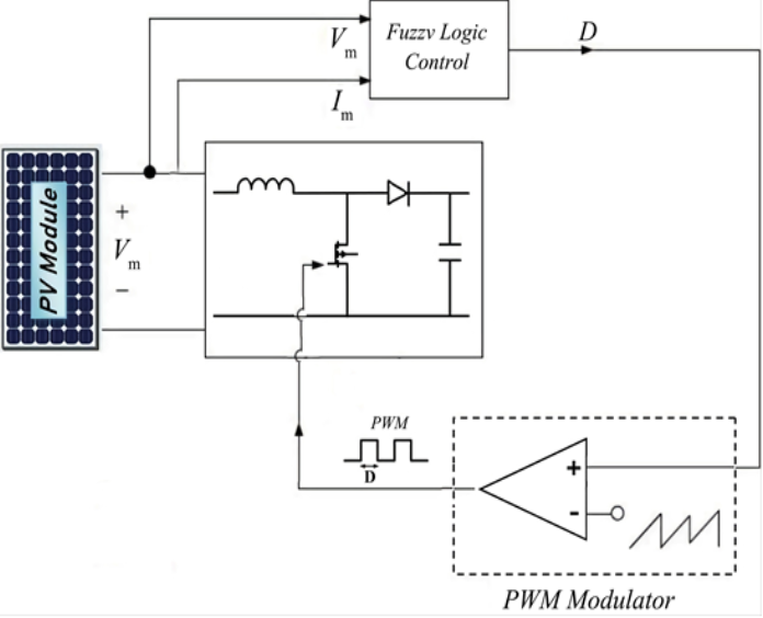
The maximum power point extraction devices are used by DC/DC converters to compensate the output voltage of the PV array in order to keep the voltage at the maximum value that optimizes output power. After extracting the output voltage and current at the PV array, the fuzzy MPPT controller is used to extract the maximum power point. The output of the fuzzy controller varies the waveform of the PWM duty cycle used to trigger the DC/DC converter.
where P(k) and V(k) are the instant power and voltage respectively of the PV generator.

Figure 2. The concept principal of MPPT fuzzy logic controller
Mamdani process of FLC is used for the MPPT. There are three methods in the FLC, those are Fuzzification, inference engine, and defuzzification.
DESIGN AND CONFIGURATION OF THE EV CIRCUIT
Boost Converter
Figure 3. The PV array connected DC-DC converter with fuzzy controller.
The system comprises of PV panel which is connected to the boost converter to boost and regulate the output voltage of the PV array. The MPPT FLC controller is used to track the maximum power from PV array. The proposed block diagram of system is given away in Fig.1.
The main purpose of the DC-DC boost converter is to steps up the input voltage to required output voltage, the components of a boost converter are diode for the freewheeling, high frequency switch (MOSFET), and an inductor. Magnitude of the output side voltage greater than the input voltage. The control stratagem is used to operate the duty cycle of MOSFET which regulates the output voltage. When MOSFET is closed, then the inductor goes to charge by the PV array source by the MOSFET. The freewheeling diode restricts the stream of current from source to the DC link capacitor. When the MOSFET is operated, then the diode is conducted in forward biased. And inductor goes to the discharges and composed with the PV array charges the capacitor.
IV. BI-DIRECTIONAL CONTROLLER CONCEPT
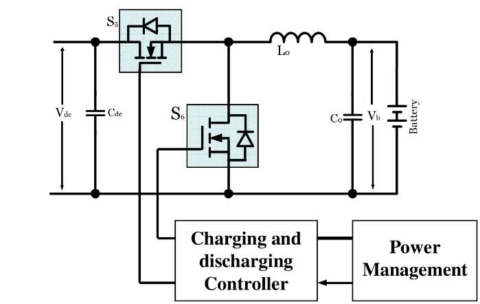
An integrated controller is proposed to simplify the controller while stabilizing the system during the mode change of the Bidirectional converter. As an example, a current mode controller is used, Figure 3 (a) depicts the typical method of using two distinct controllers, like buck and boost controllers. A power management command controls the switching between the two modes. Distinct current flow directions represent distinct modes; for example, buck mode charging current is positive, whereas boost mode discharging current is negative. In this manner, charging and discharging are only controlled by changing the reference current iL0* to positive and negative values, respectively.

Figure4. Power management controller controlled power stage of the Bidirectional converter
Using Fuzzy logic controllers can provide a resilient response for complex in the non-linear systems with load disturbance, and uncertainty. These controllers employ a highly adaptable set of if-then logic. Because of their adaptability, these controllers are becoming increasingly popular for regulating bidirectional DC-DC converters. The main advantage of utilizing this methodology is that no prior knowledge of the system's parameters is required, and, in comparison to the sliding control method, less measurements are required to construct the controller. In MATLAB Simulink, the model for both controllers with voltage control mode is evaluated, as well as the system's steady-state and transient response. Simulations revealed that the fuzzy logic control system had a steadier and dynamic response and required less settling time than the PI and PR controllers. The correlations between Dc link bus voltage Vdc and EV side battery voltage Vb, inductor current iL0, and duty cycle d are derived using this DC model. Because buck charging and boost discharging current modes use the same power plant transfer function, they can be controlled by the same unified controller.
The flow direction of the defined inductor averaged current iL0 reference is the same as the flow direction of the battery charging power. The operation between control duty cycle D and zero current duty cycles S5 and S6 determines the direction of IL0's current flow. In order to charge the battery, the inductor averaged current IL0 must be greater than zero. Similarly, duty cycle D should be increased to be greater than Do.
V. RESULTS AND DISCUSSION

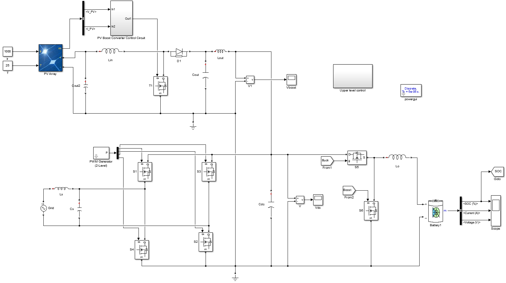
Figure5. Simulation Diagram of the Electric Vehicle with Solar Charging System
During the day time, the solar PV energy charges the electric vehicle battery. A boost converter raises the voltage of the PV panel to 200v to 400v. In this paper, a 100AH, 230 V (20 kWH) battery is used. An on-board charging circuit can be implemented at home or in parking lots.
A. Case 1: Grid to Vehicle.
 Figure6. Solar PV Array and MPPT Voltage and Current Tracking.
Solar PV array output voltage is 200V. The solar PV voltage and MPPT voltage tracking, the PV array takes 0.122s time to track the MPPT reference voltage (Vmppt) and 0.5 % steady state error.5%. Fig. 9 shows the boost converter output voltage 400V. Battery Fig. 10 shows the battery voltage and the current. Fig. 11 shows the battery state of charge during the EV charging
The PV array takes 0.022s to track the solar PV MPPT voltage. The boost converter output voltage 400V is shown in Fig. 6. Battery Figure 9. Depicts the battery voltage and current. Figure 8. Depicts the battery status of charge during EV charging.
 Figure7. Boost Converter Output DC Voltage
DC link Voltage of the boost converter is 400V.
 Figure8. Battery State of Charge during charging
State of Charge during charging of the EV from the minimum value.

 Figure9. Battery charging Voltage and Current
B. Case 2: Vehicle to grid
In this case, the bidirectional AC-DC converter serves as an inverter, controlling the output grid current. The battery provides power to the grid dependent on the needs of the grid and the convenience of the EV owner. During the charging of an electric car, switching pulses are given to a bidirectional AC-DC converter. The input voltage and current are synchronized. During charging, the battery current and voltage waveforms show a minor increase in voltage while the current waveform remains constant. During battery charging, the SOC waveform is displayed. During charging, the odd order harmonic component exists in grid voltage and current.

 Figure10. Battery discharging Voltage and Current
During discharging, the grid voltage and current waveforms are out of phase with the grid voltage are shown in the fig12. It demonstrates how power travels from the EV battery to the power grid. During battery draining, the voltage and current waveforms decrease while the voltage wave remains constant. The battery's state of charge (SOC) when discharging is shown in the fig11.
 Figure11. SOC during discharging
 Figure12. Grid Current and Voltage Current waveforms
Conclusion
The solar PV system is designed to create an output voltage of 200 volts, which is then stepped up to 400 volts using a boost converter. The output voltage is filtered, and the filtered voltage is step-down to meet the charging requirements of an EV battery using a buck converter. The foregoing goals are met by modeling the mathematical architecture of the PV system and simulating the PV system under various weather situations using a fuzzy-based MPPT system. The fuzzy-based energy management system is designed and tested under a variety of power demands, and the functioning of battery charging and discharging is then examined. SOC has been found to be efficient in both charging and discharging modes. Based on the frequency response characteristic, a corner frequency of 10 rad/s was suitably chosen. Voltage and current in-phase and out-of-phase are used to depict EV charging from the grid and battery energy given back to the grid. In a high power bidirectional dc-dc converter, the proposed unified controller performs well. Load step up and down tests under both buck charging and boost draining modes confirm stable operation. The results show that the derived model is correct and can be used in the construction of a unified controller to ensure constant current charging and discharging. Solar charging solves voltage issues and overloading in the distributed network caused by additional producing units and increased power demand caused by a greater number of EVs charging from the grid.
References
[1] Nian Liu, Oifang Chen, Xinvi Lu, Jie Liu and Jianhua Zhang, “A Charging Strategy for PV-Based Battery Switch Station Considering Service Availability and Self-Consumption of PV Energy,” IEEE Trans. Ind Electronics., vol.62, no.8, pp. 4878-4889, Feb 2015. [2] K. Chaudhari, A. Ukil, K. N. Kumar, U. Manandhar and S. K. Kollimalla, “Hybrid Optimization for Economic Deployment of ESS in PV-Integrated EV Charging Stations,” IEEE Trans. Ind. Informatics, vol. 14, no. 1, pp. 106-116, Jan 2018. [3] Bhim Singh, Anjeet Verma, A. Chandra and Kamal Al-Haddad, “Implementation of Solar PV-Battery and Diesel Generator Based Electric Vehicle Charging Station,” in IEEE International Conference on Power Electronics, Drives and Energy Systems (PEDES), 2018. [4] Hoang N. T. Nguyen, Cishen Zhang, and Jingxin Zhang, “Dynamic Demand Control of Electric Vehicles to Support Power Grid With High Penetration Level of Renewable Energy,” IEEE Trans. Transportation Electrification, vol. 2, no. 1, pp. 66-75, Mar 2016. [5] Xie W, Hui J. MPPT for PV system based on a novel fuzzy control strategy. In: 2010 International Conference on Digital Manufacturing & Automation; ChangSha; 2010. pp. 960-963 [6] Anandhakumar G, Venkateshkumar M, Shankar P. Intelligent controller based MPPT method for the photovoltaic power system. In: 2013 International Conference on Human Computer Interactions (ICHCI); Chennai; 2013. pp. 1-6 [7] Indumathi R, Venkateshkumar M, Raghavan R. Integration of D-Statcom based photovoltaic cell power in low voltage power distribution grid. In: IEEE-International Conference on Advances in Engineering, Science and Management (ICAESM-2012); Nagapattinam, Tamil Nadu; 2012. pp. 460-465 [8] M. C. Kisacikoglu, B. Ozpineci, and L. M. Tolbert, “EV/PHEV bidirectional charger assessment for V2G reactive power operation,” IEEE Trans. Power Electron., vol. 28, no. 12, pp. 5717–5727, Dec. 2013. [9] By Xiaosong Hu, Chagfu Zou, Caiping Zhang, And Yang Li, “Technological Developments in Batteries” IEEE power& energy magazine, pp. 20- 31, Sep/Oct 2017. [10] X. Zhou, S. Lukic, S. Bhattacharya, and A. Huang, “Design and control of grid-connected converter in Bi-directional battery charger for plugin hybrid electric vehicle application,” in Proc. IEEE Veh. Power and Propulsion Conf., pp. 1716–1721, Sep 2009. [11] D.N. Zmood, D.G. Holmes, “Stationary frame current regulation of PWM inverters with zero steady-state error,” IEEE Trans. Power Electron, vol. 18, no.3, pp. 814-822, May 2003. [12] A.V.J.S.Praneeth, Najath A Azeez, Lalit Patnaik, Sheldon S Williamson, ‘‘Proportional Resonant Controllers in On-board Battery Chargers for Electric Transportation,’’ IEEE International Conference on Industrial Electronics for Sustainable Energy Systems (IESES). pp. 237-242, 2018. [13] De Brito, M.A.G., Junior, L.G., Sampaio, L.P., Melo, G.A.E. and Canesin, C.A. (2011) Main Maximum Power Point Tracking Strategies Intended for Photovoltaics. XI Brazilian Power Electronics Conference, Natal, 11-15 September, 524-530. [14] Sahu, P., Sharma, A. and Dey, R. (2020) Ripple Correlation Control Maximum Power Point Tracking for Battery Operated PV Systems: A Comparative Analysis. 2020 IEEE International IOT, Electronics and Mechatronics Conference, Vancouver, 9-12 September 2020, 1-6. [15] Trivedi, A., Gupta, A., Pachauri, R.K. and Chauhan, Y.K. (2017) Comparison of Perturb & Observe and Ripple Correlation Control MPPT Algorithms for PV Array. 2016 IEEE 1st International Conference on Power Electronics, Intelligent Control and Energy Systems, Delhi, 4-6 July 2016, 1-5. [16] Belkaid, A., Colak, U. and Kayisli, K. (2017) A Comprehensive Study of Different Photovoltaic Peak Power Tracking Methods. 2017 IEEE 6th International Conference on Renewable Energy Research and Applications, San Diego, 5-8 November 2017, 1073-1079. [17] Ibnelouad, A., El Kari, A., Ayad, H. and Mjahed, M. (2017) A Comprehensive Comparison of the Classic and Intelligent Behavior MPPT Techniques for PV Systems. 2017 14th International Multi-Conference on Systems, Signals & Devices, Marrakech, 28-31 March 2017, 526-531. [18] Hamed, B.M and El-Moghany, M.S. (2012) Fuzzy Controller Design Using FPGA for Photovoltaic Maximum Power Point Tracking. International Journal of Advanced Research in Artificial Intelligence, 1, 14-21. [19] Ali, A.I.M., Mohamed, E.E.M. and Youssef, A.R. (2018) MPPT Algorithm for Grid-Connected Photovoltaic Generation Systems via Model Predictive Controller. 2017 Nineteenth International Middle East Power Systems Conference, Cairo, 19-21 December 2017, 895-900. [20] Samosir, A.S., Gusmedi, H., Purwiyanti, S. and Komalasari, E. (2018) Modeling and Simulation of Fuzzy Logic Based Maximum Power Point Tracking (MPPT) for PV Application. International Journal of Electrical and Computer Engineering, 8, 1315-1323.
Copyright
Copyright © 2024 Banoth Balavidyasri , Dr. JBV. Subrahmanyam. This is an open access article distributed under the Creative Commons Attribution License, which permits unrestricted use, distribution, and reproduction in any medium, provided the original work is properly cited.

Download Paper
Paper Id : IJRASET63921
Publish Date : 2024-08-09
ISSN : 2321-9653
Publisher Name : IJRASET
DOI Link : Click Here
 Submit Paper Online


