Ijraset Journal For Research in Applied Science and Engineering Technology
- Home / Ijraset
- On This Page
- Abstract
- Introduction
- Conclusion
- References
- Copyright
Damping Behavior of Diamond like Coatings on Aluminum Foams
Authors: Dr. N. Stanley Ebenezer, K. Sarath, Ch. V. V. Sushanth, R. Abhiram, S. Srinivas
DOI Link: https://doi.org/10.22214/ijraset.2024.62788
Certificate: View Certificate
Abstract
Metal foams offer a compelling combination of properties, including low density, sound absorption, high compressive strength, and stiffness. This project focuses on the damping behavior of aluminum foams for applications in automobiles and various industries. Aluminum foams excel in being lightweight, exhibiting high compressive strength, and offering excellent stiffness. However, their wear resistance is a limitation. To address this and enhance durability, a diamond-like carbon (DLC) coating is applied to the surface. The complex geometry and surface of aluminum foams pose a challenge for the coating process. Therefore, the project employs the well-established cataphoretic deposition technique, an electro-chemical process. This research investigates the potential of carbon-coated aluminum foam for vibration mitigation in automobiles and industrial applications by analyzing its damping properties and improved wear resistance through the DLC coating. By using a melt method, aluminum foams with 0.35, 1.0, and 1.7 vol.% DLC-coated carbon fibers were created. The damping characteristic of Al foam at room temperature was examined. According to the experimental results, the amount of carbon fibers in Al foam causes the critical strain amplitude to drop and its damping ability to rise. The microplasticity deformation is caused by a microcrack at the DLC-Al interface. Furthermore, compared to the longitudinal direction, the transverse direction has a stronger damping characteristic.
Introduction
I. INTRODUCTION
Metal Foams is a man-made porous medium that has a solid of metal with empty or fluid-filled voids. If the voids are connected via open pores, the foam is described as open cell, if the voids are not connected via open channels, and are separated by solid walls; the foam is referred to as being closed-cell. The number of pores per linear inch (ppi) currently ranges from 5 to 100. Obviously, each type of foam lends itself to suitable applications. The ratio of the void space to the total volume of a piece of foam is called the porosity. Metal foam can have very high porosities (up to 0.98 or 0.99). The high porosity makes metal foams very lightweight a fact that renders them extremely attractive as an industrial technology for applications where weight is a primary design constraint. Some of the foams are produced with hollow structures to make them even lighter. Metal foam is characterized structurally by its cell topology (open cells, closed cells), relative density, cell size and cell shape and anisotropy. Density is best measured by weighing a sample of known volume; the rest require microscopy. Optical microscopy is helpful in characterizing metal foams provided that the foam is fully impregnated with opaque epoxy (or equivalent) before polishing. This requires that the foam sample be immersed in a low viscosity thermoset containing a colouring agent (black or deep blue is best), placed in a vacuum chamber and degassed and then re-pressurized to force the polymer into the cells. The procedure may have to be repeated for closed cell foams after coarse polishing, since this often opens a previously closed cell. At this point in time most commercially available metal foams are based on aluminum or nickel. Methods exist for foaming magnesium, lead, zinc, copper, bronze, titanium, steel and even gold, available on custom order. Given the intensity of research and process development, it is anticipated that the range of available foams will expand quickly over the coming years. Although foams have the high damping properties it has been found that there are some properties which are having lack in that foams so coatings on metal substrates have elevated the damping capacities and wear resistance to a much higher extent than the uncoated specimens. Regarding scientific and engineering applications, DLC coatings have garnered a great deal of interest. Amorphous carbon compounds come in various forms that contain DLC. The mechanical, civil, aerospace, automotive, biomedical, marine, and various other production industries use DLC coatings because of their wide range of qualities. DLC's production processes and component parts are the main factors that affect its coating life. A multitude of studies have been conducted by various researchers in order to obtain a solid grasp of DLC coatings and its innate ability to prolong component life. The types of DLC on the ternary graph are shown in the following figure, which also shows the division of the targets in the combination; i.e., C sp3, C sp2, or H, according to Jacob and Moller’s recommended graph. The outline of the stage consists of three main areas: (1) without H a-C along with the left pivot, (2) sp2 a-C is commonly lustrous C or a-C produced by dissipation, and (3) cutting-edge variations of faltering, including uneven magnetron faltering, can make DLCs with an enormous sp3 substance. At considerably maximum sp3 content, there is an explicit sort of a-C assigned as tetrahedral shapeless C. This is produced using plasma particles or radiation with high particle splitting and almost no characteristic particle energy.
The categorization, characteristics, and uses of a broad variety of DLC coatings are covered in this report. DLC coatings are a bright alternative to conventional solitary-coating techniques because of their outstanding performance in a range of applications. DLC is a group of amorphous carbon (C) compounds with a special quality seen in diamonds. Different material composites have been coated using a variety of processes, giving them more superior and multipurpose uses, such as marine and biomedical engineering. Moreover, DLC reveals the seven different shapes of its large-scale sp3 hybridized C molecules in the form of a diamond. DLC coatings are created by combining poly-type materials in a distinct way to create nanoscale structures that are both formless and adaptive, but only have sp3 reinforcement, just like a diamond. Tetrahedral amorphous carbon is the name given to this combination, which is the hardest and most grounded.
II. EXPERIMENTAL PROCEDURE
A. Preparation Of Aluminium Foams
The production of Aluminum foams has been carried out by the casting process. This includes the following steps
1) Preparation of Patterns: In pattern making we created a detailed drawing of the final cast object including perfect dimensions and tolerances. We have chosen wood as the pattern material for better surface finish. And the pattern is designed to a cuboidal shape with smooth finish by using different wood-working techniques. And the shrinkage, shake and machining allowances are given. Patterns should be easy to replace, repair and reuse. Patterns should be easy to service and maintain. Pattern material should be durable and sustainable to changes in temperature and moisture content Should ensure consistency in the quality of the final casting.
2. Molding Process: The sand casting process with single piece pattern has been chosen for the production of aluminium foams. Casting involves following components at workprocess: Pattern, Molding sand, Binders, Additives, Parting compound, Cope and drag, Reamers, Gate cutters, Runner and riser. For starting the molding process the initial part is preparation of molding sand by sieving sand into fine powder, then binders and additives are added to sand and mixed thoroughly to convert it into a fine mixture.
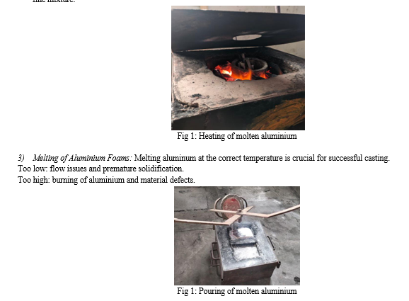
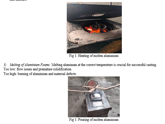
For melting of aluminium a crucible furnace has been chosen. The crucible is made of ceramics which can withstand high temperatures 1200°F.The crucible is placed carefully in the furnace initially loaded with hybrid coal and preheated using blower. Then Aluminum ingots are melted in the furnace at a precisely controlled temperature, typically around 650 700°C (1200-1300°F). Aluminium metal after getting into molten state the foaming agents are introduced to get foam structure to the aluminium foams. The Chemical Blowing Agents are chosen as foaming agents, these are salts or compounds that decompose upon reaching a certain temperature, releasing gases like nitrogen or carbon dioxide. Titanium Hydroxide (TiH2), Calcium carbonate (CaCO3), Sodium chloride (NaCl) is a common example. Titanium Hydroxide (TiH2) is mixed with molten aluminium to get the foam structure.
B. Coating On Aluminium Foams
While the Foams are having the pores on the surface, it will be somewhat complicated to produce the coating using the CVD, Spraying processes so that a new form of coating method which is the process of cataphoresis is introduced in this scenario. Cataphoretic coating is a process that deposits a metal coating on a substrate using an electric current. The detailed procedure for cataphoretic coating of aluminum typically involves the following steps:
- Surface Preparation: The aluminum surface must be thoroughly cleaned to remove any contaminants. This can include degreasing, desmutting, and etching to ensure proper adhesion of the plating.
- Pre-Treatment: After cleaning, the aluminum may undergo various pre-treatment processes such as zinc immersion, which helps to improve the adhesion of the subsequent metal layers
- Electroplating: The actual electroplating process involves immersing the aluminum part in an electrolyte solution containing metal ions. When an electric current is applied, the metal ions are reduced and begin to deposit on the aluminum surface.
The working of cataphoretic coating process involves a series of steps where chemical reactions are driven by the application of an electrical current. Cataphoretic coating cell is set up with two electrodes: the anode (positive) and the cathode (negative), immersed in an electrolyte solution that can conduct electricity. When a voltage is applied, ions in the electrolyte move. Positive ions (cations) move towards the cathode, and negative ions (anions) move towards the anode. At the anode, oxidation occurs where electrons are lost, and at the cathode, reduction takes place where electrons are gained. These are redox (reduction-oxidation) reactions. Electrons flow through the external circuit from the anode to the cathode. This flow of electrons is the electric current. As a result of these reactions, new substances can be formed at the electrodes. For example, metal ions can be reduced to form a solid metal coating on the cathode. The electrolyte participates in the reaction to balance the charge and may also undergo changes.
- Post-Treatment: After plating, the aluminium part may undergo post-treatment processes such as passivation or sealing to enhance the corrosion resistance and durability of the coating.
- Quality Control: Throughout the process, quality control measures are taken to ensure the thickness, adhesion and overall quality of the metal coating meet the required specifications.
The most important process parameters in a cataphoretic deposition are the voltage applied V and the deposition time t. While t has been maintained constant, with a value of 120 s, four different values of V have been tested, in order to highlight its influence on the property of the coating. The used voltage were 150, 200, 250 and 300 V. Below 150 V, coatings show very low thickness, while for voltages higher than 300 V, pinholes rich coatings are obtained (probably due to hydrogen evolution at the interface with the substrate). After the deposition, the samples have been subjected to a curing process, at 180 °C for 20 min, following the supplier’s recommendations.
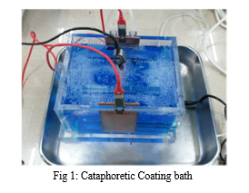
During the deposition itself, the current values circulating in the bath were monitored, thorough the Easy Power Lite software, of the EA Elektro-Automatik GmbH&Co PSI 8360 current generator, in order to obtain information about the deposition rate and make some assumptions about the dimension of the coatings of the different samples. The coated samples have been observed by the optical stereo microscope (Nikon SMZ25) and in order to measure the thickness of the coatings and observe the presence of defects, such as bubbles and not completely coated cells. For this purpose the incorporating resin has been mixed with a vibrant purple high-fluidity liquid for two reasons:
Increase the contrast between resin, coating and substrate, facilitating the observation of the protective layer;
Decrease the viscosity of the resin, allowing it to reach the entire surface of the sample, even in the deepest cavity.
III. RESULTS AND DISCUSSIONS
After etching, micro-structural and surface morphological characterizations have been comprehensively examined. The SEM image of the DLC Coated Aluminium foam, shows how pores are incorporated into the core matrix system with increase in porosity. It has been seen that the pores have been formed, providing the requisite stress concentrations to raise the total micro-plasticity.
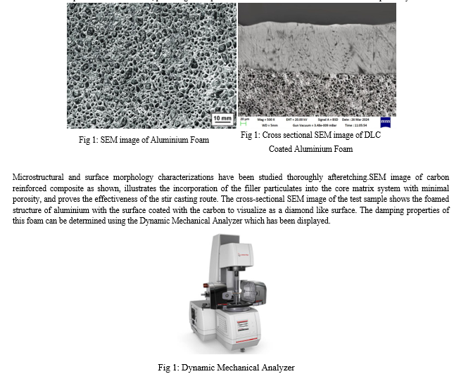
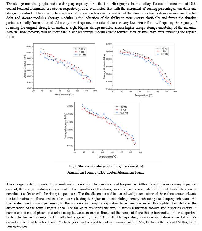
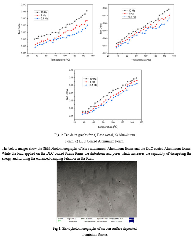
The overall damping behaviour of the test samples can be understood by regarding all the aforesaid damping approaches. The enhanced damping characteristics of the metal foams has been developed due to the impregnation of liquid carbon deposit on the surface by using the cataphoretic coating process which has not only developed the damping properties but also increased the corrosion, sound absorption properties and so on.
Conclusion
In this work cataphoretic deposition has been investigated as a potential route to coat aluminum foams. In particular, the effect of the applied voltage has been assessed. It has been evidenced that it is very difficult to obtain a uniform coating on the entire surface of aluminum foam sample. The complex surface morphology of the foam in fact does not ensure to obtain a coating of the appropriate thickness, especially inside the cavities on the surface. The process of cataphoresis however, seems to be a promising technique for coating surfaces of this type, as it can get fairly good results, by acting on the potential value applied during the deposition. By using the molt process, aluminum foams reinforced with carbon fibers have been effectively created. The amount of carbon decreases with the critical strain amplitude. The dampening capability of aluminium Foams will increase with the amount of Carbon present. The enhanced damping ability can be ascribed to the growing interfacial microslip and microplasticity deformation, which originate from the micro-crack present in the interface. The anisotropic cell shape accounts for the variation in damping properties seen in Al/Cf foams. Compared to the longitudinal direction, the transverse direction has a stronger damping characteristic. The strain amplitude and Carbon contents have minimal impact on the loss factor ratio. But it is worth mentioning that replicated aluminum possesses higher mechanical properties, such as specific Young’s modulus and tensile strength. Combined with good damping properties, it proved to be more attractive material for designing in the fields of vibro-protection and mechanical energy absorption. According to the results, the most appropriate pore size of replicated aluminum is 1.6–3.0 mm that corresponds to metal foam damping behavior.
References
[1] M.F. Ashby, A.G. Evans, N.A. Fleck, L.J. Gibson, J.W. Hutchinson, H.N.G. Wadley, Metal Foams: A Design Guide, Butterworth-Heinemann, Woburn, MA, 2000. [2] J. Banhart, Manufacture characterization and application of cellular metals and metal foam, Prog. Mater. Sci. 46 (2001) 559–632. [3] A. Antenucci, S. Guarino, V. Tagliaferri, N. Ucciardello, Electrodeposition of graphene on aluminum open cell metal foams, Mater. Des. 71 (2015) 78–84. [4] S. Rossi, M. Fedel, L. Da Col, F. Deflorian, S. Petrolli, Coatings to increase the corrosion behaviour of aluminium foam, Surf. Eng. 33 (2017) 405–409. [5] N. Movahedi, A. Habibolahzadeh, Effect of plasma electrolytic oxidation treatment on corrosion behavior of closed-cell Al-A356 alloy foam, Mater. Lett. 164 (2016) 558–561. [6] Kuchek, H. A. (1964). Patent US 3138856 Method of producing clad porous metal articles. [7] Despois, J.-F. (2005). Replicated aluminium foam, processing and properties, Ecole Politechnique Federale de Lausanne, p. 265. [8] Furman, E. L., Finkelstein, A. B., & Cherny, M. L. (2013). Permeability of aluminium foams produced by replication casting. Metals, 3(1), 49–57. [9] Furman, E. L., Finkelstein, ?. B., & Cherny, M. L. (2014). The anisotropy of replicated aluminum foams. Advances in Materials Science and Engineering,1–6. [10] Golovin, I. S., Sinning, H. R., Göken, J., & Riehemann, W. (2003). Amplitude dependent damping of some metallic foams. Solid State Phenomena, 89, 267–272. [11] Zhang, Y., Ma, N., & Wang, H. (2007). Effect of particulate/Al interface on the damping behavior of in situ TiB2. Materials Letters, 61, 3273–3275. [12] Göken, J., & Riehemann, W. (2002). Thermoelastic damping of the low density metals AZ91 and DISPAL. Materials Science and Engineering A, 324(1–2), 134–140. [13] Kazantsev, S. P., & Husnullin, D. V. Technological processes of obtaining of replicated aluminium foam. Contemporary Engineering Sciences, 8(16), 723–727. [14] Golovin, I. S., & Sinning, H.-R. (2003). Damping in some cellular metallic materials. Journal of Alloys and Compounds, 355(1–2), 2–9. [15] Granato, A., & Lücke, K. (1956). Theory of mechanical damping due to dislocations. Journal of Applied Physics, 27(6), 583.
Copyright
Copyright © 2024 Dr. N. Stanley Ebenezer, K. Sarath, Ch. V. V. Sushanth, R. Abhiram, S. Srinivas. This is an open access article distributed under the Creative Commons Attribution License, which permits unrestricted use, distribution, and reproduction in any medium, provided the original work is properly cited.

Download Paper
Paper Id : IJRASET62788
Publish Date : 2024-05-27
ISSN : 2321-9653
Publisher Name : IJRASET
DOI Link : Click Here
 Submit Paper Online

