Ijraset Journal For Research in Applied Science and Engineering Technology
- Home / Ijraset
- On This Page
- Abstract
- Introduction
- Conclusion
- References
- Copyright
Deck Slab Skewness Behavior on Pier and Longitudinal Girder of Balanced Cantilever Bridge: An Analytical Study
Authors: Khushboo Verma, Dr. Raghvendra Singh
DOI Link: https://doi.org/10.22214/ijraset.2024.65806
Certificate: View Certificate
Abstract
The finite element method (FEM) analysis of balanced cantilever skew bridges under the higher loading class of IRC 6:2017 is explored in this study. The impact of increased skewness in the deck on other structural members of the bridge is examined. For the analysis, a portion of a bridge with a span of 14 meters and a lane width of 3.5 meters is considered. Seven cases are created and analyzed using various skew angles. After the analysis, checks are performed to evaluate how the performance of the deck slab influences other bridge components, including the longitudinal girder. Conclusions are drawn regarding the pier and longitudinal girder based on the results. It is found that greater skewness in the deck slab leads to increased values of parameters such as axial forces, shear forces, bending moments, and torsional moments in the bridge. The analysis demonstrates a direct proportionality between the skew angle and the magnitude of stress, highlighting the critical role of skewness in structural performance evaluations.
Introduction
I. INTRODUCTION
In modern infrastructure, large distances are spanned with minimal support using balanced cantilever skew bridges, especially over obstacles like rivers, railways, and highways. Their adaptability, reduced construction time, and minimal disturbance to the terrain have been prioritized in the current scenario. The alignment of structures with oblique crossings, such as angled intersections or irregular layouts, is facilitated by the inclusion of skewness in bridge design to optimize land usage and traffic flow. Complexities in load distribution and structural behavior are caused by skew angles, resulting in non-uniform stress patterns and differential deflections. Increased torsion, reduced load capacity, and challenges in deck slab design are frequently encountered in comparison to straight bridges. These issues are mitigated through the use of advanced tools like finite element methods, ensuring structural safety and performance. The adoption of balanced cantilever methods, combined with careful consideration of skew angles, is recognized as an efficient solution for modern transportation networks.
II. OBJECTIVES OF THE PRESENT STUDY
Following heads shows the objectives selected for the current study and need to fulfil to achieve research goal. The objectives for behavior of other structural members by skewness on balanced cantilever bridge are:-
- To study the effect of skewness of deck slab on pier by comparing maximum axial forces in pier and compare the efficient case among (CB-FEM1 to CBFEM7) for all the cases of deck skewness.
- To conduct the study on the deviation in maximum shear forces in pier and find out the efficient case among (CB-FEM1 to CBFEM7) for all the cases of deck skewness.
- To determine the variation in maximum bending moment in pier and find out the efficient case among (CB-FEM1 to CBFEM7) for all the cases of deck skewness.
- To estimate the dissimilarity in maximum torsional moment in pier and find out the efficient case among (CB-FEM1 to CBFEM7) for all the cases of deck skewness.
- To study the deviation in maximum shear forces and bending moment in longitudinal girder and find out the efficient case among (CB-FEM1 to CBFEM7) for all the cases of deck skewness.
- To conduct the study on the dissimilarity in maximum torsional moment in longitudinal girder and find out the efficient case among (CB-FEM1 to CBFEM7) for all the cases of deck skewness.
- To recommend the feasibility of research on effect of deck slab skewness over other structural members by analysing the result parameters by FEM analysis.
A. Output Result Parameters Selected
It is essential to use various output parameters that will require analyzing the behavior of each case. Some of the selected output result parameters are:-
B. For Pier
- Axial forces in pier
- Shear forces in pier
- Bending moment in pier
- Torsion moment in pier
C. For Longitudinal Girder
- Shear forces in longitudinal girder
- Bending moment in longitudinal girder
- Torsion moment in longitudinal girder
III. PROCEDURE AND 3D MODELING OF STRUCTURE
To analyze the balanced cantilever skew bridge, addressing gaps in previous research requires developing various models to ensure precision in comparative assessments. The Indian Standard IRC 6:2000 is utilized as a reference, offering diverse loading types and configurations for obtaining reliable outcomes. Based on this, the models are to be generated systematically, following a specific sequence. Detailed input data and descriptions of the models are provided as follows:-
- The grade of concrete taken as M30 with FE500 grade of steel.
- IRC loading taken as 70R with dead load as self weight.
- Width of lane taken as 3.5 m, 300 mm thickness of deck slab taken into account and span taken as 14m respectively.
- Dimensions of longitudinal girder taken as 0.4m x 0.8m, cross girder as 0.4m x 0.8m, height of pier as 10m for smooth passing of the vehicle under it and diameter of pier taken as 1.2m.
- 0 degree, 7 degree, 14 degree, 21 degree, 28 degree, 35 degree and 42 degree skew angles taken for analysis
Detailed data for various cases used for skew analysis and abbreviations of the models selected as follows:-
- CB-FEM1- Cantilever bridge with FEM analysis at 0 degree skew angle under 70R loading
- CB-FEM2- Cantilever bridge with FEM analysis at 7 degree skew angle under 70R loading
- CB-FEM3- Cantilever bridge with FEM analysis at 14 degree skew angle under 70R loading
- CB-FEM4- Cantilever bridge with FEM analysis at 21 degree skew angle under 70R loading
- CB-FEM5- Cantilever bridge with FEM analysis at 28 degree skew angle under 70R loading
- CB-FEM6- Cantilever bridge with FEM analysis at 35 degree skew angle under 70R loading
- CB-FEM7- Cantilever bridge with FEM analysis at 42 degree skew angle under 70R loading
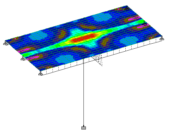
Fig. 1: Plate stress contour view of CB-FEM1
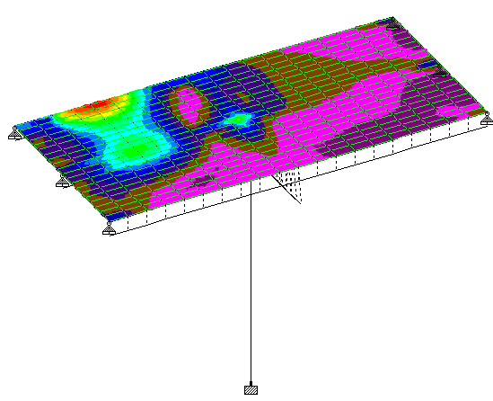
Fig. 2: Plate stress contour view of CB-FEM2
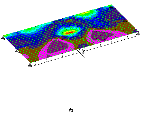
Fig. 3: Plate stress contour view of CB-FEM3
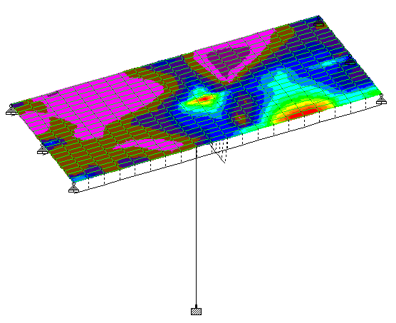
Fig. 4: Plate stress contour view of CB-FEM4
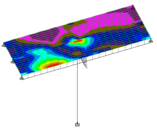
Fig. 5: Plate stress contour view of CB-FEM5
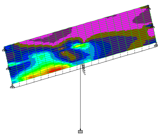
Fig. 6: Plate stress contour view of CB-FEM6

Fig. 7: Plate stress contour view of CB-FEM7
IV. RESULTS AND DISCUSSION
As per the objectives and the parameters selected for for behavior of other structural members by skewness on balanced cantilever bridge, the following results were obtained as follows:-
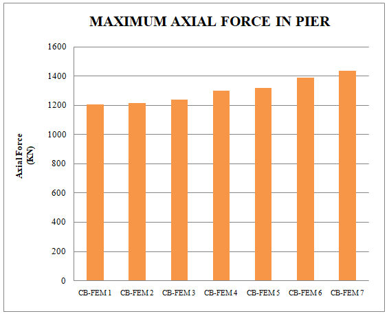
Fig. 8: Maximum Axial forces in pier for all cases
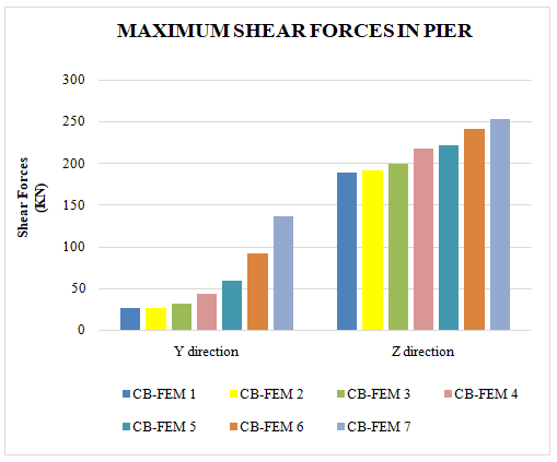

Fig. 9: Maximum Shear forces and Bending Moment in pier for all cases
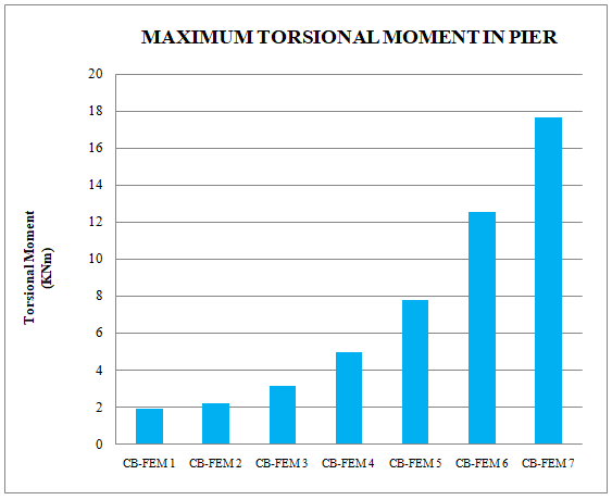
Fig. 10: Maximum Torsion Moment in pier for all cases
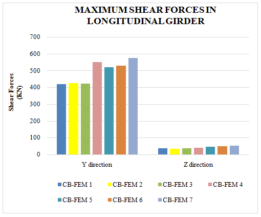
Fig. 11: Maximum Shear in longitudinal girder for all cases
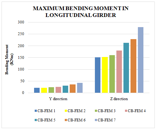
Fig. 12: Maximum Bending Moment in longitudinal girder for all cases
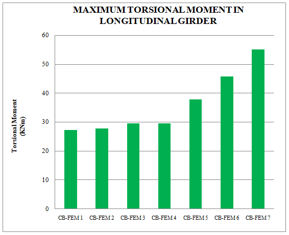
Fig. 13: Maximum Torsion Moment in longitudinal girder for all cases
Conclusion
On the basis of above parameters, following conclusions obtained on other members of balanced cantilever skew bridge from this comparative study:- A. For Pier 1) On comparing 0 degree, with increase in skew angle, the axial forces in pier increases by 18.91% respectively for 300mm depth. 2) The shear forces in longitudinal girder increases by 429% in Y direction and 33.27% in Z direction respectively with increase in skew angle from 0 to 42 degree. 3) The bending moment in longitudinal girder increases by 33.93% in Y direction and 424.946% in Z direction respectively with increase in skew angle from 0 to 42 degree. 4) The torsional moment in longitudinal girder increases by 822.28% respectively with increase in skew angle from 0 to 42 degree. B. For Longitudinal Girder 1) On comparing 0 degree, with increase in skew angle, the axial forces in pier increases by 18.91% respectively for 300mm depth. 2) The shear forces in longitudinal girder increases by 37.31% in Y direction and 49.88% in Z direction respectively with increase in skew angle from 0 to 42 degree. 3) The bending moment in longitudinal girder increases by 101.27% in Y direction and 85.45% in Z direction respectively with increase in skew angle from 0 to 42 degree. 4) The torsional moment in longitudinal girder increases by 102.309% respectively with increase in skew angle from 0 to 42 degree. This project concluded that the more skewness of the deck will generate results in higher side, since the members are interconnected with each other, it should be noted that the skewness of the deck affects the other structural members such as pier and longitudinal girder of the balanced cantilever skew bridge andthe higher results generated by the skewed deck slab during simulation by FEM analysis will be directly proportional to the degree of the skewness. The recommendation will be usage of lesser degree will be benefitted to the bridge components respectively.
References
[1] Dhar, A., Mazumder, M., Chowdhury, M., & Karmakar, S., (2013), “Effect of Skew Angle on Longitudinal Girder (support shear, moment, torsion) and Deck Slab of an IRC Skew Bridge”, Indian Concrete Journal. [2] Rocha, B. F., & Schulz, M., (2017), “Skew decks in reinforced concrete bridges”, Revista IBRACON De Estruturas E Materiais, Vol. 10, Issue 1, pp. 192–205. [3] Jeswani, B., & Budhlani, D., (2020), “Analysis And Design Of Bridge Component Using Staad Pro”, International Journal of Creative Research Thoughts (IJCRT), Vol. 8, Issue 9, pp. 121–122. [4] Gayatri Deshmukh, Prof. Pandurang S. Patil, (2022), “Analysis of performance of various skew angles of deck slab bridges in MIDAS Software”, International Research Journal of Engineering and Technology (IRJET), ISSN: 2395-0056, Volume: 09 Issue: 07, pp. 2781-2784. [5] Vasu Shekhar Tanwar, Sagar Jamle, (2018), \"Analysis of Box Culvert to Reduce Stress Values\". International Journal of Advanced Engineering Research and Science (ISSN: 2349-6495(P) | 2456-1908(O)), vol. 5, no. 5, pp.103-105 AI Publications, doi:10.22161/ijaers.5.5.14. [6] Ibrahim S. I. Harba, (2011), “Effect Of Skew Angle On Behavior Of Simply Supported R. C. T-Beam Bridge Decks”, ARPN Journal of Engineering and Applied Sciences, ISSN 1819-6608, Vol. 6, No. 8, pp. 1-14. [7] Kishan Gautam, Shashikant Shrivastava, (2020), “Skew Bridge Analysis using “ANSYS””, International Journal of Engineering Research & Technology (IJERT), Vol. 9, Issue 06, pp. 870-875. [8] Kristine Djuve et. al. (2019), “Analysis Of Varying Skew Angle In A Single Span Reinforced Concrete Plate Bridge”, Conference Paper; University of Stavanger. [9] L.A. Abozaid, Ahmed Hassanet. al. (2014), “Nonlinear Behaviour of a Skew Slab Bridge under Traffic Loads”, World Applied Sciences Journal, ISSN 1818-4952, Vol. 30, Issue 11, pp. 1479-1493. [10] Lakavath Ramesh, B. Ravi Kumar, (2017), “Finite Element Modeling Of Reinforcemented Cement Concrete Skew Bridge And Dynamic Analysis”, Anveshana’s International Journal Of Research In Engineering And Applied Sciences, ISSN-2455-6300, Vol. 2, Issue 1, pp. 210-215. [11] Lucía Moya, Eva O. L. Lantsoght, (2021), “Parametric Study on the Applicability of AASHTO LRFD for Simply Supported Reinforced Concrete Skewed Slab Bridges”, infrastructures, Vol. 6, Issue 88, pp. 1-23. [12] Muthanna Abbu, Talha Ekmekyapar, Mustafa Özakça, (2013), “3D FE modelling of composite box Girder Bridge”, 2nd International Balkans Conference on Challenges of Civil Engineering, BCCCE, pp. 487-494. [13] Nasir, Himanshu Guleria, (2019), “Review On Skew Slab Bridges”, International Research Journal of Engineering and Technology (IRJET), ISSN: 2395-0056, Vol. 06, Issue 12, pp. 1559-1561. [14] Nikhil V. Deshmukh, Dr. U. P. Waghe, (2015), “Analysis and Design of Skew Bridges”, International Journal of Science and Research (IJSR), ISSN: 2319-7064, Vol. 4, Issue 4, pp. 399-402. [15] Pavankumar Naik, K Gourav, (2023), “Analysis Of Skew Bridge-Slab Under IRC Vehicle Loading”, IOP Conf. Series: Earth and Environmental Science, ITSCMSI-2022. [16] Roshan Patel, Sagar Jamle, (2019), “Analysis and Design of Box Culvert: A Review”, International Journal for Research in Engineering Application & Management (IJREAM), ISSN-2454-9150, Vol. 5, Issue 1, pp. 266-270. [17] Pinkal Gohel, Patel Sweta, Pandey Vipul, Nikunj Patel, (2017), “Analysis & Design of Deck Slab under Different Types of Loading as per is Code by STAAD Pro Software”, IJSRD - International Journal for Scientific Research & Development, ISSN: 2321-0613, Vol. 5, Issue 08, pp.361-364. [18] R. Javanmardi, B. Ahmadi-Nedushan, (2021), “Cost Optimization Of Steel-Concrete Composite I-girder Bridges With Skew Angle And Longitudinal Slope, Using The SM Toolbox And The Parallel Pattern Search Algorithm”, International Journal Of Optimization In Civil Engineering,Int. J. Optim. Civil Eng., Vol. 11, Issue 3, pp. 357-382. [19] R. Shreedhar, Spurti Mamadapur, (2012), “Analysis of T-beam Bridge Using Finite Element Method”, International Journal of Engineering and Innovative Technology (IJEIT), ISSN: 2277-3754, Vol. 2, Issue 3, pp. 340-346. [20] Vasu Shekhar Tanwar, Dr. M. P. Verma, Sagar Jamle, (2018), “Analytic Study of Box Culvert to Reduce Bending Moment and Displacement Values”, International Journal of Current Engineering and Technology, IJCET, Vol. 8, no. 3, pp. 762-764, DOI: https://doi.org/10.14741/ijcet/v.8.3.33 [21] Roshan Patel, Sagar Jamle, (2019), “Analysis and Design of Box Culvert: A Manual Approach”, International Journal of Advanced Engineering Research and Science (IJAERS), ISSN: 2349-6495, Vol. 6, Issue 3, pp. 286-291. [22] Rahna Sajeeb, Adithya Viswambharan, (2021), “Finite Element Modelling and Dynamic Analysis of Skew Bridge using Staad. Pro”, International Journal of Engineering Research & Technology (IJERT), ISSN: 2278-0181, Special Issue – 2021, Vol. 9, Issue 9, pp. 102-105.
Copyright
Copyright © 2024 Khushboo Verma, Dr. Raghvendra Singh. This is an open access article distributed under the Creative Commons Attribution License, which permits unrestricted use, distribution, and reproduction in any medium, provided the original work is properly cited.

Download Paper
Paper Id : IJRASET65806
Publish Date : 2024-12-08
ISSN : 2321-9653
Publisher Name : IJRASET
DOI Link : Click Here
 Submit Paper Online

