Ijraset Journal For Research in Applied Science and Engineering Technology
- Home / Ijraset
- On This Page
- Abstract
- Introduction
- Conclusion
- References
- Copyright
Design & Analysis of G+10 Building with Composite Column
Authors: Mohd. Azheruddin, Mohammad Hafeez, Mohammed Sameer, Mohd Mazheruddin
DOI Link: https://doi.org/10.22214/ijraset.2024.63420
Certificate: View Certificate
Abstract
As the world business enlarging day by day, and designing of the buildings are getting complex and demanding more technology to enhance its stability, performances, cost, duration and its uniqueness of designing. At the later part of development in civil engineer majority of the work was transformed from conventional system to a well organized and computerized system, most of the time the company employees and owners were in live risk, due to non availability of technology. As time goes technology develops, having this in mind we had also suggested using Etabs software in our design. Etabs is a 3D analysis and designing of the buildings, it is engineering software which is used in construction and designing or analysis of complex multi stored buildings. Composite column is actually the amalgamation of two traditionally methodologies structure steel and structure concrete, their design could be based on concrete or steel methodology. Any method can be used to develop composite column approach. Composite columns are designed by applying different components of structure steel and concrete in according to use the advantages and property of each material. The outer and inner behavior of the concrete and structural steel ingredients make the Composite column is very unbending, enough squashy, cost effective and generally makes it efficient partner of the building and bride constructions. Normally three kinds of composite column sections are using in high risky building construction. The building was analyzed by using Etabs and designed according to the needed requirement. Composite column technology for construction of building is now a day’s very popular and has more advantages over the conventional designing of buildings, currently we see tall buildings with great advantages such as less space more accommodation, parking, and many more, these all can only be achieved if we implement the concept and idea of composite construction. This is why composite construction is so good; the one line reason behind this is that it combines both steel and concrete into one unit. By combining these materials can strengthen and provide best result in extremely enough and light weight design. Composite by column can also save our time and we can construction the complex buildings in short term. One of the biggest achievement if is done in construction by composite column is the cost reduction, because most of the constructions companies are being lost and dropped its position due to non profitability.
Introduction
I. INTRODUCTION
In recent years, the construction of multi-storied buildings has increased significantly due to urbanization and the growing demand for residential and commercial spaces. Ensuring the structural integrity and safety of these buildings, especially in earthquake-prone regions. Pushover analysis involves applying a gradually increasing lateral load pattern to a building model until it reaches a target displacement or collapses. This method provides valuable insights into the inelastic behavior of structures, including the sequence of yielding, formation of plastic hinges, and potential failure mechanisms. By simulating these conditions, engineers can predict how a building will perform during an earthquake, identify weak points, and propose necessary retrofits or design modifications to improve resilience. ETABS (Extended Three-Dimensional Analysis of Building Systems) is a sophisticated software application widely used in the field of structural engineering for modeling, analyzing, and designing buildings. ETABS offers robust tools for conducting pushover analysis, allowing engineers to simulate various loading conditions and structural responses with high accuracy. Its user-friendly interface and comprehensive analytical capabilities make it an ideal choice for this type of analysis. This project focuses on performing a pushover analysis of a multi-storied building using ETABS. The primary objectives are to:
Model a Building: Create an accurate three-dimensional model of the building, including all structural elements such as beams, columns, slabs, and walls, based on architectural and structural design plans.
Define Seismic Load Patterns: Apply lateral load patterns as per relevant seismic codes and standards to simulate earthquake forces acting on the building.
Assess Structural Behavior: Analyse the results to assess the overall seismic performance of the building, identify weaknesses, and suggest potential improvements or retrofitting measures. Through this project, we aim to enhance our understanding of the seismic behavior of buildings and demonstrate the practical application of using ETABS. This study will contribute to the broader field of earthquake engineering by providing insights that can help improve the safety and resilience of high-rise structures in seismic regions. At the purpose when a structure is exposed to seismic tremor, it reacts by vibrating. A seismic tremor power is often settled into three commonly opposite bearings the 2 even headings (x and y) and therefore the vertical course(z). This movement makes the structure vibrate or shake in all of the three bearings; the overwhelming heading of shaking is even. All of the structures are essentially intended for gravity loads-power like mass time’s gravity within the vertical heading. In light of the natural factor of wellbeing utilized within the plan particulars, most structures will generally be enough secured against vertical shaking. Vertical increasing speed need to likewise be considered in structures with huge ranges, those during which dependability for plan, or for generally speaking strength examination of structures. In general, linear procedures are applicable when the structure is expected to remain nearly elastic for the level of ground motion or when the design results in nearly uniform distribution of nonlinear response throughout the structure. As the performance objective of the structure implies greater inelastic demands, the uncertainty with linear procedures increases to a point that requires a high level of conservatism in demand assumptions and acceptability criteria to avoid unintended performance. Therefore, procedures incorporating inelastic analysis can reduce the uncertainty and conservatism.
ETABS stands for EXTENDED 3D ANALYSIS OF BUILDING SYSTEMS, a software developed by Computers and Structures Inc. ETABS is an engineering software that can be used to analyse and design multistorey buildings using grid like geometry, various methods of analysis and solution techniques, considering various load combinations. Incorporating 40 years of continuous research and development, this software offers an unmatched 3D object-based modelling and visualization tools, which possess blazingly fast linear and non- linear analytical power, along with the sophisticated and comprehensive design capabilities for a wide range of materials and provides a variety of insightful graphic displays, reports and schematic drawings that allow users to quickly and easily understand the obtained analysis and design results respectively. Microsoft Excel is a spreadsheet developed by Microsoft for Windows, macOS, Android and iOS. It features calculation or computations, graphic tools, pivot tables and a macro programming language called Visual Basic for Applications (VBA). Microsoft Excel has the basic features of all spreadsheets using a grid of cells arranged in numbered rows and letternamed columns to organize data manipulations like arithmetic operations. It has a battery of supplied functions to answer statistical, engineering and financial needs. In addition to this, it can display data as line graphs, histograms and charts, and with a very limited three-dimensional graphical display.
Composite columns are designed to optimize structural performance by combining different materials, typically concrete and steel. The primary objectives of building with composite columns include:
- Strength and Stability: Composite columns offer higher strength and stability compared to traditional columns, allowing for taller and more complex structures to be built.
- Space Efficiency: They can provide greater usable floor space due to their smaller cross-sectional area compared to conventional columns of similar load-carrying capacity.
- Cost Efficiency: By using less material while maintaining structural integrity, composite columns can lead to cost savings in construction projects.
- Architectural Flexibility: Composite columns allow for more innovative architectural designs since they can support heavier loads with smaller dimensions, giving architects more freedom in their designs.
II. LITERATURE SURVEY
K. Naga Sai Gopal & n. Lingeshwaran have done the work on this paper. In this study the design of the structure is based on ETABS and Limit state method not only provide adequate strength, serviceability, and durability but also economy. Displacement, Shear force, bending moment variation has been shown. And they also do find stress analysis in slab, shear force for the beam and area reinforcement for the column and design the foundation depends upon the reaction and height of the foundation level depends upon site and safe bearing capacity of the soil due to stability purpose designed the retaining wall in this project. If in case of any beam fails, the beam and column are changed and reinforcement detailing can be updated.
Pushkar Rathod and Rahul Chandrashekar [2017] With the help of seismic analysis, the structure can be designed and constructed to withstand the high lateral movement of earth’s crust during an earthquake. The research examines the impact of stiffness on building overstrength, displacement ductility, fragility for Life Safety, and collapse limit states. Any type of basic or a highly advanced structure which maybe under static or dynamic conditions can be evaluated by using ETABS, ETABS is a coordinated and productive tool for analysis and design which range from a simple 2D frames to modern high-rises which makes it one of the best structural software for building systems.
Shubhangi Jha et.al (2020) [6] The purpose of this research is to analyze and study how tall, plus- shaped buildings that have bracing systems oriented differently respond to wind loads. When the height of large buildings increases, the impact of wind load on the building becomes increasingly significant. The prototype building had a ground floor height of 4.5 meters and subsequent floor heights of 3.3 meters, following the G+35 design. Less axial force values were represented by the single diagonal bracing system. The axial force readings indicate a relatively gradual decline from the building's base to its thirty percent height, followed by a sharp decline to its summit.
Fangwei Hou and Mohammad Jafari (2020) [9] This paper analyzes previous studies on wind response in tall buildings, offering detailed information on the mechanism and identification methodologies. Identification of wind-induced load parameters using wind tunnel test.Understanding wind-induced reaction can improve urban sustainability by designing taller buildings that are less subject to wind loads, resulting in more energy-efficient and occupant- friendly communities. Quantifying wind- induced loads and responses on high-rise buildings is crucial, using both traditional and modern methods. This paper provides a comprehensive assessment of current methodologies for studying wind-induced responses in tall buildings.
Mahesh Kumar , Shwetha , Sunil, Raghavendra Vol. 04 (2017) [10] In this paper they considered G+10 floors. They applied various loads on building such as dead load, live load and earthquake load. Then analyzing the behavior of structure subjected to combination of loads using the E- TABS software. And from the equivalent static analysis, they can clearly see that there is an increasing order in the values obtained for cumulative storey shear, displacement, storey drift and overturning moment are follows in the order of soil-I, soil-II and soil-III types in all zones in both X direction. Therefore cumulative storey shear force, displacement, storey drift and overturning moment of zones are affected by different soil types and the Soft Soil type is the critical. For the irregularity building considering the equivalent static method for different zone and soil type.
III. METHODOLOGY
The In this project, we embark on analysis of G+10 structures utilizing Pushover Analysis techniques. These structures represent typical mid-rise buildings and are subjected to rigorous evaluation under seismic loading conditions. Pushover Analysis, a nonlinear static procedure, allows us to simulate the progressive collapse behavior of structures under lateral forces, providing valuable insights into their seismic performance The architectural features, dimensions, and structural configurations have been meticulously considered to ensure a representative analysis. By subjecting these structures to Pushover Analysis, we aim to understand their response characteristics, including deformation patterns, redistribution of forces, and potential failure modes, under seismic loading.
Composite construction had become the International standard construction method in different countries in short period of time, Because of its brilliant benefits. It is the most acceptable system to resist in earthquake loadings. Most of the countries are willing to use the composite construction; the method is yet to become the most popular. The present paper is concerned with composite column weather steel or concrete a column and building frame which contains composite column.
ETABS is an engineering software product that provides to multi-story building analysis and design. Modeling tools and templates, code-based load prescriptions, analysis methods and solution techniques, coordinate with the grid-like geometry unique to this class of structure. Basic or advanced system under static or dynamic conditions may be evaluated using ETABS
The methodology followed for the Modelling and Analysis of the Structures is:
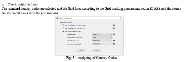
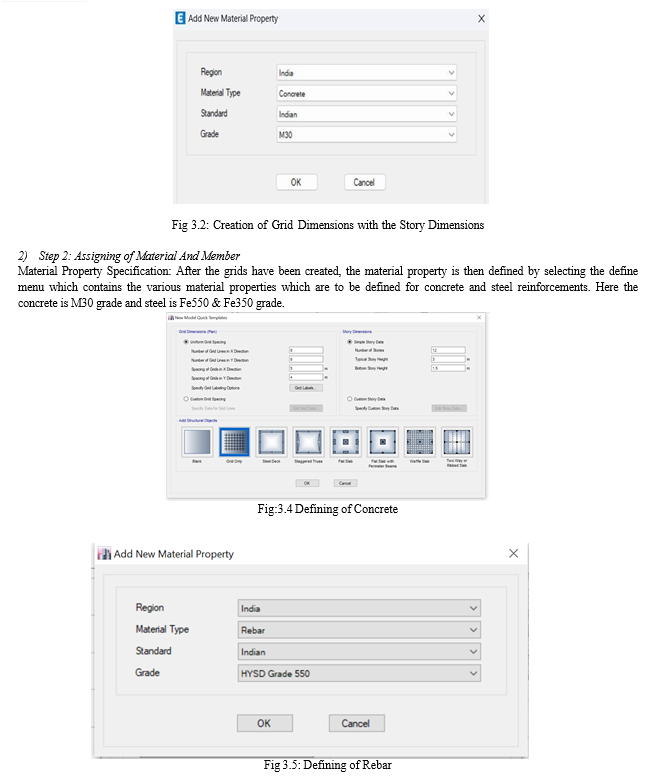
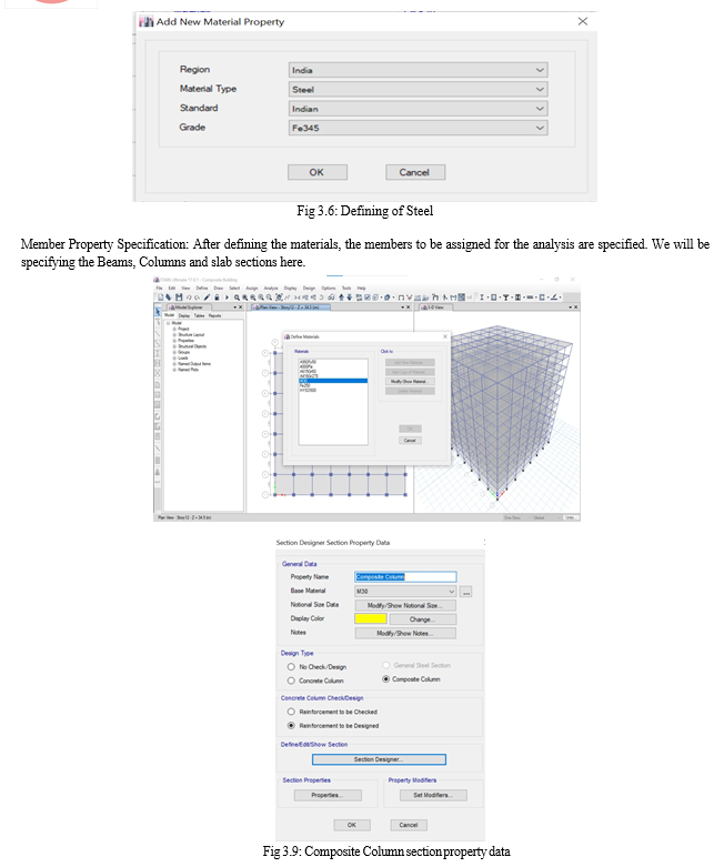
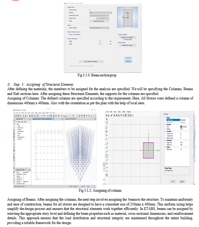
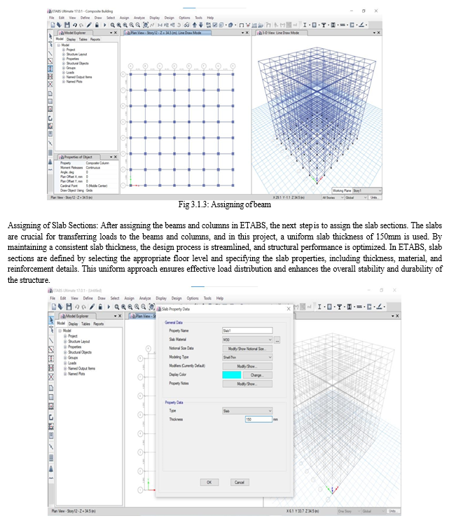
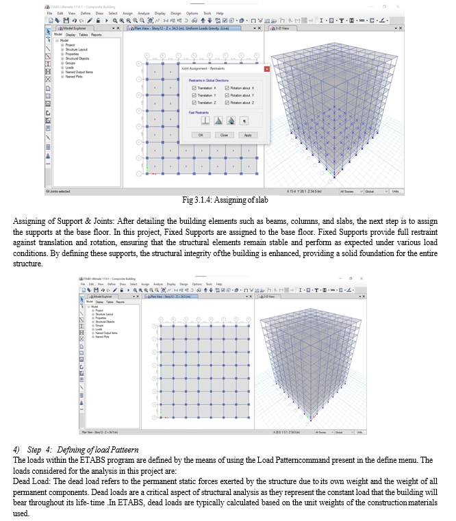
These unit weights are established according to the guidelines provided in IS 875 (Part I): 1987, which outlines the code of practice for design loads (other than earthquake) for buildings and structures. The unit weights are derived from the specified materials used in construction, such as concrete, steel, masonry, and other relevant materials. One of the advantages of using ETABS is that it can automatically calculate the dead loads based on the defined material properties and geometry of the structural elements. This automation eliminates the need for manual input of dead load values, reducing the possibility of human error and ensuring accuracy in the analysis. The program computes these loads by considering the volume and density of the materials, thereby generating the appropriate load values for each structural component.This automated process not only saves time but also ensures that the load calculations are consistent and compliant with the relevant codes and standards.
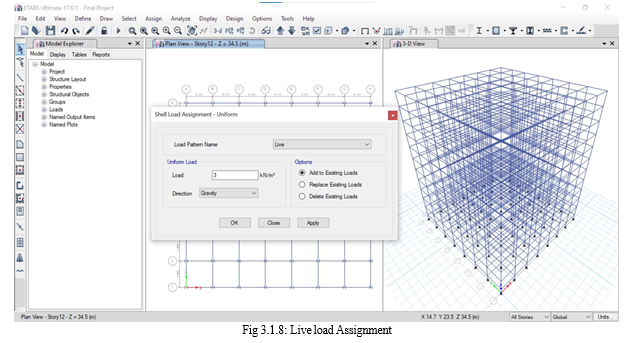
Live Load: In ETABS, live loads are the imposed loads assumed in the building design based on the intended use or occupancy. These loads represent the maximum anticipated forces from occupants, furniture, and movable equipment but must meet or exceed the minimum loads specified in IS 875 (Part 2): 1987. Floors must be analyzed for uniform distributed loads (UDL) and corresponding concentrated loads to ensure structural integrity. Unlike dead loads, live loads are variable and do not include environmental loads such as wind, earthquake, or snow. By accurately defining live loads in ETABS, the structural analysis ensures that the building can safely support its intended use without compromising safety and performance.
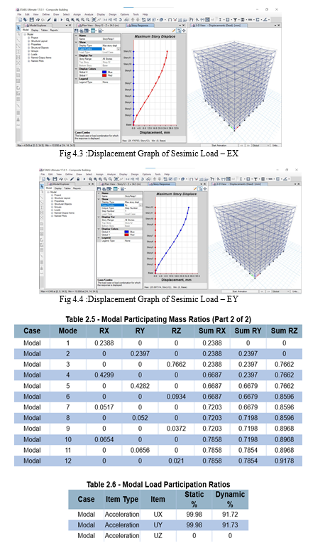
Seismic Load: In ETABS, seismic loading refers to the forces exerted on a structure during an earthquake event. These loads are significant only in regions designated as high earthquake zones, while they are typically disregarded in areas with lower seismic activity. Seismic forces are dynamic and affect structures in both the X and Y directions, necessitating consideration in both dimensions during analysis. The calculation of seismic loading follows guidelines outlined in IS 1893:2016. In ETABS, seismic analysis often employs the Equivalent Static Analysis method. By incorporating seismic loading into the structural analysis, engineers ensure that the design can withstand the intense forces generated by earthquakes, thereby enhancing the safety and resilience of the structure in high seismic risk areas.
5. Step 5 : Defining Of Load Combination
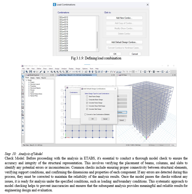
Load combinations in structural analysis are crucial for assessing the safety of a building under diverse loading scenarios. They represent various combinations of loads acting simultaneously on the structure to evaluate its response to different design conditions. These combinations are essential for ensuring that the structure can withstand the maximum expected loads without experiencing failure or excessive deformation.
In this project, a comprehensive set of load combinations is applied to account for factors such as dead loads, live loads, floor finishes, brick loads, seismic forces in both X and Y directions, and wind forces in both X and Y directions. By considering these combinations, engineers can accurately predict the structural behavior and design elements that ensure the safety and integrity of the building under a range of realistic loading conditions.
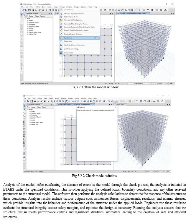
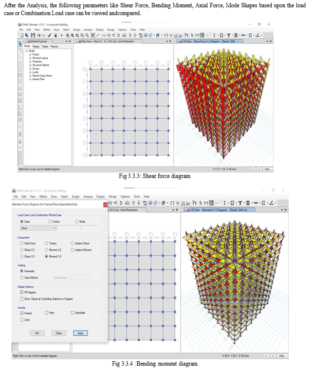
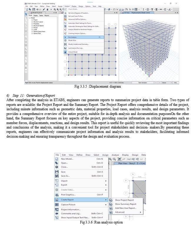
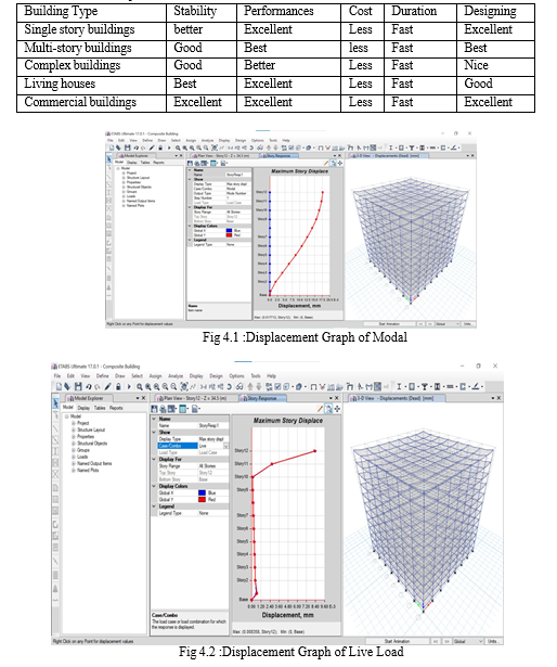
Conclusion
Composite construction had brought a huge revolution in construction environment, as well as in Construction Company, the implementation of composite construction had totally changed the environment of the company, we have also concluded that composite construction does influence upon the strategy of the company. According to the survey little idea of the people was concerned with composite construction, the survey also clarified that composite construction has more reliability then the conventional ones.The main objective of the survey was to motivate and convinced the owners of construction companies to implement the idea of composite construction. Experimental work as also done during the survey by using different material as a unit and also used as an individual to illustrate the differences, The stiffness and rigid was also tested and had proved positively. The research states composite construction is the key selection in such areas where earthquake chances are more. Below table shows some of the characteristics of composite construction. In conclusion, we compare seismic analysis of a G+10 building with different columns have provided valuable insights into the performance of conventional and composite columns under earthquake conditions. Through detailed modeling and analysis, we observed distinct behaviors and responses in each system. It is evident that the choice of column significantly influences the seismic performance of a high-rise structure. This study contributes to the ongoing efforts in designing structures that are resilient to seismic forces, enhancing safety and reliability in regions prone to earthquakes. Further research and real-world validation could deepen our understanding and refine these insights, ultimately advancing seismic resistant building practices. In engineering applications, the design and analysis of composite structures comparing to conventional column demand a nuanced understanding of material interactions, load-bearing capacities, and failure modes. Software tools like ETABS facilitate the intricate task of modeling, analyzing, and optimizing composite members, offering a comprehensive approach to ensuring structural integrity and compliance with industry standards. In this study, the seismic design and performance of composite steel-concrete structures are discussed in particular. Comparison of parameters like time period, moments and load carrying capacity is done with steel and Reinforced cement concrete structures. The results are compared and it is found that composite structure are more good in several aspects. A. Benefits of Composite Construction 1) The benefits of composite construction include speed of construction, performance and value. The concrete provides additional stiffness to the structure. 2) Additionally, the concrete protects the steel from fire 3) High degree of prefabrication & steel connections allow quick assembly, Lighter construction than a Traditional Concrete Building 4) Building quality standards can be adhered easily by the use of Composite Structures
References
[1] Tushar D Patil, Rohan P Joshi, Kaustubh M Manudhane, Abhijit A Shinde, Vipul S Tekawade, Dr. Vidya R Saraf, “Static Analysis and Design of G+20 RCC Framed Structure by using ETABS Software [2] “(International Journal for Research in Applied Science & Engineering Technology (IJRASET) Volume 11 Issue IV Apr 2023). [3] Zhao, Q. and Astaneh-Asl, A. (2007) Seismic behavior of composite shear wall systems and application of smart structures technology. International Journal of Steel Structures, 7(7), 69-75. [4] Wang, Z. and Zhang, Z. (2020) High-rise modular buildings with innovative precast concrete shear walls as a lateral force resisting system. Structures, 26, 39-53, https:// doi.org/10.1016/j.istruc.2020.04.006. [5] B. Umamaheshwara and P. Nagarajan, (August 2016) “Design Optimization and Analysis of Shear Wall in High Rise Buildings Using ETABS,” International Journal for Research in Applied Science & Engineering Technology, vol. 4, no. 8, pp. 480-488. [6] Prieto-Portar, Jorge, et al. \"Shear Wall Design Based on Linear Dynamic Analysis and Numerical Optimization.\" Proceedings of the Institution of Civil Engineers - Structures and Buildings, vol. 170, no. 4, 2017, pp. 243-258. [7] R.P. JOHNSON (2004) Composite structure of steel and concrete volume1 Blackwell publication, U.K. [8] S.S. BHAVIKATTI, Design of steel structures (By limit state method as per IS 800-2007). [9] HANSWILLE, R. P..: Composite structures and concrete-beams, slabs, columns and frames for buildings (3rd edition), London [10] AISC (2005). Specification for Structural Steel Buildings, American Institute of Steel Construction, Chicago, IL (to appear). [11] Dowling, P. J., Harding, J. E. and Bjorhovde, R. (1992). Constructional Steel Design An International Guide, Elsevier Applied Science, 961 [12] Elremaily, A. and Azizinamini, A. (2002). “Behavior and Strength of Circular Concretefilled Tube Columns,” Journal of Constructional Steel Research, 58(12), 1567-1591. [13] Galambos, T. V., and Chapuis, J. (1980). LRFD Criteria for Composite Columns and Beam-Columns, Revised Draft, Washington University, Dept. of Civil engineering, St. Louis, MO, December. [14] Giakoumelis, G. and Lam, D. (2003). “Axial Capacity of Circular Concrete-filled Tube Columns,” Journal of Constructional Steel Research, 60(7), 1049-1068. [15] Han, D. J. and Kim, K. S. (1995). “A study on the Strength and Hysteretic Characteristics of Steel Reinforced Concrete Columns,” Journal of the Architectural Institute of Korea, 11(4), 183-190. [16] Han, D. J., Kim P. J. and Kim K. S. (1992). “The Influence of Hoop Bar on the Compressive Strength of Short Steel Reinforced Concrete Columns,” Journal of the Architectural Institute of Korea, 12(1), 335-338. [17] Han, L. and Yan, S. (2000). “Experimental Studies on the Strength with High Slenderness Ratio Concrete Filled Steel Tubular Columns,” Proceedings of 6th ASCCS Conference Los Angeles, USA, March 22-24, 419-425. [18] Han, L. and Yao, G. (2000). “Influence of Concrete Compaction on the Strength of Concrete-filled Steel RHS Columns,” Journal of Constructional Steel Research, 59(6), 751-767. [19] Hardika, M. S. and Gardner, N. J. (2004). “Behavior of Concrete-filled Hollow Structural Section Beam Columns to Seismic Shear Displacements,” ACI Structural Journal, 101(1), 39-46. [20] Johansson, M., Claeson, C., Gylltoft, K. and Akesson, M. (2000). “Structural Behavior of Circular Composite Columns Under Various Means of Load Application,” Proceedings of 6th ASCCS Conference Los Angeles, USA, March 22-24, 427-433. [21] Johnson R. P. and Anderson D. (1993). Designers’ Handbook to Eurocode 4, Tomas Telford, London, 182 pp [22] Kang, C. H., Oh, Y. S. and Moon, T. S. (2001). “Strength of Axially Loaded Concretefilled Tubular Stub Column,” International Journal of Steel Structures, Korean Society of Steel Construction, 13(3), 279-287 [23] Kang, H. S., Lim, S. H. and Moon, T. S. (2002). “Behavior of CFT Stub Columns Filled with PCC on concentrically Compressive Load,” Journal of the Architectural Institute of Korea, 18(9), 21-28. [24] Kenny, J. R., Bruce, D. A. And Bjorhovde, R. (1994). “Removal of yield Stress Limitation for Composite Tubular Columns, Engineering Journal, 31(1), 1-11. [25] Kilpatrick, A. and Rangan, B. V. (2000). “Behavior of High-strength Composite Columns,” Conventional and Innovative, International Conference Innsbruck, Austria, September 16-18, 789-794. [26] Kvedaras, A. Tomaszewicz, A. (1994). “Thin Steel Mantle as Lateral Confinement in Reinforced Concrete Columns: Technical and Economical Consideration,” Steel-Concrete Composite Structures, Proceeding of the 4th ASCCS International Conference, 115-118. [27] Lee, S. J., Park, J. M. and Kim, W. J. (2002). “Capacity Properties of High-Strength Concrete Filled Square Steel Tube Column Under Centric Load,” Journal of the Architectural Institute of Korea, 18(7), 11-18. [28] Leon, R. and Aho, M. (2000). “Towards New design Provisions for Composite Columns,” Proceeding of the Conference,” Composite Construction in Steel and Concrete ?, 518-527. [29] Matsui, C., Mitani, I., Kawano, A., Tsuda, K. (1997). “AIJ Design Method for Concrete Filled Steel Tubular Structure,” ASCCS Seminar, Innsbruck, 93-115. [30] Mirza, S., Hyttinen, V. and Hyttinen, E. (1996). “Physical Tests and Analyses of Composite Steel Concrete Beam-Columns,” Journal of Structural Engineering, ASCE, 122(11), 1317-1326. [31] O’Shea, M. D. and Bridge, R. Q. (2000). “Design of Circular Thin-walled Concrete-filled Steel Tubes,” Journal of Structural Engineering, ASCE, 126(11), 1295-1303. [32] O’Shea, M. D. and Bridge, R. Q. (1997). “Circular Thin-walled Tubes with High Strength Concrete Infill,” Proceedings of the Engineering Foundation Conference, ASCE, 780-793. [33] Roeder, C. W., Cameron, B. and Brown, C. B. (1999). “Composite Action in Concrete filled tubes,” Journal of Structural Engineering, ASCE, 125(5), 477-484. [34] Roik, K. and Diekmann, C. (1989). “Experimental Studies on Composite Columns Encased in Concrete Following Loading,” Der Stahlbau, 58(6), 161-164. [35] Schneider, P. S. (1998). “Axially Loaded Concrete-filled Steel Tubes,” Journal of Structural Engineering, ASCE, 124(10), 1125-1138. [36] Seo, S. Y. and Chung, J. A. (2002). “An Experimental Study on Strength of Slender Square Tube Columns Filled with High Strength Concrete,” International Journal of Steel [37] Structures, Korean Society of Steel Construction, 14(4), 471-479
Copyright
Copyright © 2024 Mohd. Azheruddin, Mohammad Hafeez, Mohammed Sameer, Mohd Mazheruddin . This is an open access article distributed under the Creative Commons Attribution License, which permits unrestricted use, distribution, and reproduction in any medium, provided the original work is properly cited.

Download Paper
Paper Id : IJRASET63420
Publish Date : 2024-06-22
ISSN : 2321-9653
Publisher Name : IJRASET
DOI Link : Click Here
 Submit Paper Online

