Ijraset Journal For Research in Applied Science and Engineering Technology
- Home / Ijraset
- On This Page
- Abstract
- Introduction
- Conclusion
- References
- Copyright
Design & Development of Automatic Battery Cooling System Using Air Blower and Temperature Sensor
Authors: Rajendra Ghatode, Bhushan Karamkar, Mahesh Ghorpade, Om Golande, Saurabh Kedar, Pankaj Pawar
DOI Link: https://doi.org/10.22214/ijraset.2024.62399
Certificate: View Certificate
Abstract
This paper presents a comprehensive review of the design and development of automatic battery cooling systems employing air blower and temperature sensor technologies. With the growing demand for electric vehicles (EVs) and renewable energy storage systems, efficient thermal management of batteries is imperative to ensure their longevity, safety, and optimal performance. Traditional passive cooling methods often fall short in dynamically regulating battery temperature, especially under varying operating conditions. Consequently, active cooling systems have garnered significant attention due to their ability to actively control battery temperature. This review outlines various approaches and methodologies adopted in the design and implementation of automatic battery cooling systems. It discusses the integration of air blowers and temperature sensors into these systems to achieve real-time monitoring and precise thermal regulation. Additionally, the paper examines different system architectures, control strategies, and sensor placements utilized to optimize cooling effectiveness while minimizing energy consumption.
Introduction
I. INTRODUCTION
In the realm of electric vehicles (EVs) and renewable energy storage systems, the efficient management of battery temperature stands as a critical determinant of performance, safety, and longevity. As the demand for sustainable transportation and energy solutions continues to surge, there is an escalating need for advanced thermal management technologies to ensure the optimal functioning of batteries under varying operating conditions. Among the myriad strategies employed to address this challenge, automatic battery cooling systems incorporating air blowers and temperature sensors have emerged as promising solutions. The conventional passive cooling methods, although simple and cost-effective, often prove inadequate in dynamically regulating battery temperature, especially during high-demand scenarios or extreme environmental conditions. In contrast, active cooling systems offer the capability to actively monitor and control battery temperature in real-time, thereby enhancing efficiency, reliability, and overall battery lifespan. This transition from passive to active cooling represents a significant paradigm shift in battery thermal management, driving innovation and technological advancements in the field.
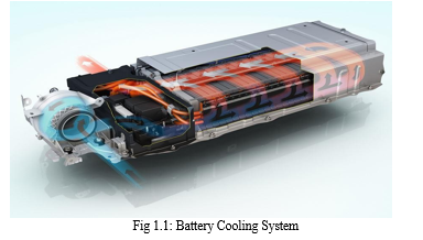
This review aims to provide a comprehensive examination of the design and development of automatic battery cooling systems utilizing air blower and temperature sensor technologies. By exploring various methodologies, system architectures, control strategies, and advancements in this domain, the review seeks to elucidate the pivotal role played by air blowers and temperature sensors in optimizing battery performance and safety. Additionally, it aims to analyze emerging trends, challenges, and future research directions in automatic battery cooling technology, thereby offering valuable insights to researchers, engineers, and industry practitioners involved in the design and implementation of battery thermal management systems.
II. METHODOLOGY
Step-by-step methodology for conducting a CFD analysis of a battery air cooling system using Ansys Workbench, with the given condition of an initial air temperature of 22 degrees Celsius:
- Geometry Creation:
- Start by creating a detailed 3D model of the battery cooling system geometry using a CAD software or within Ansys Design Modeler if available.
- Ensure the model accurately represents all components including the battery, cooling ducts, inlet, outlet, and any other relevant features.
2. Mesh Generation:
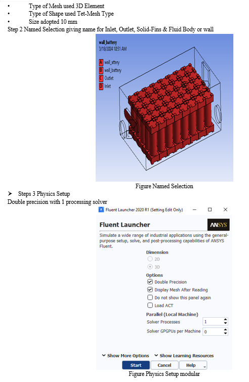
- Import the geometry into Ansys Workbench.
- Generate a mesh using Ansys Meshing module.
- Pay attention to mesh quality, especially near walls and regions of interest.
- Refine the mesh as necessary to ensure accurate results, especially in areas of high temperature gradients.
3. Material Properties:
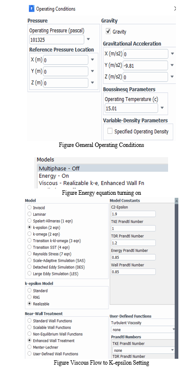
- Define material properties for all components involved in the simulation, including the battery, cooling ducts, and surrounding air.
- Specify thermal conductivity, density, and specific heat capacity for air and other materials as appropriate.
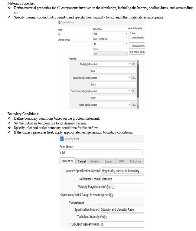
4. Boundary Conditions:
- Define boundary conditions based on the problem statement.
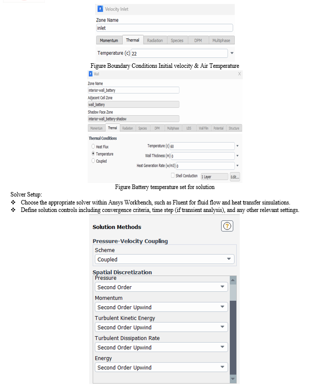
- Set the initial air temperature to 22 degrees Celsius.
- Specify inlet and outlet boundary conditions for the airflow.
- If the battery generates heat, apply appropriate heat generation boundary conditions.
5. Solver Setup:
- Choose the appropriate solver within Ansys Workbench, such as Fluent for fluid flow and heat transfer simulations.
- Define solution controls including convergence criteria, time step (if transient analysis), and any other relevant settings.
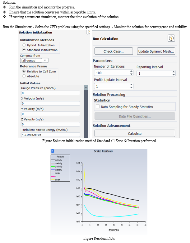
6. Solution:
- Run the simulation and monitor the progress.
- Ensure that the solution converges within acceptable limits.
- If running a transient simulation, monitor the time evolution of the solution.
7. Post-Processing:
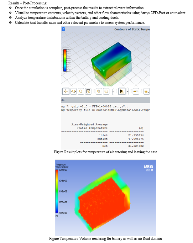
- Once the simulation is complete, post-process the results to extract relevant information.
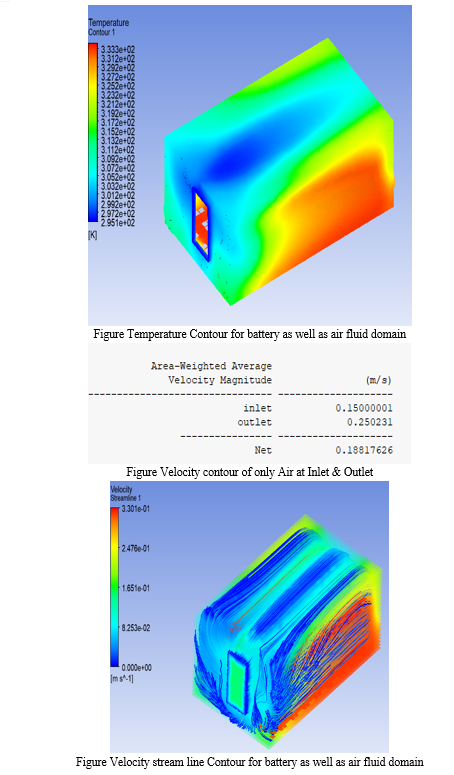
- Visualize temperature contours, velocity vectors, and other flow characteristics using Ansys CFD-Post or equivalent.
- Analyze temperature distributions within the battery and cooling ducts.
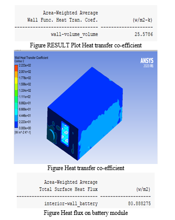
- Calculate heat transfer rates and other relevant parameters to assess system performance.
8. Analysis and Optimization:
- Analyze the results to identify areas for improvement or optimization.
- Make design changes as necessary to enhance system performance, such as modifying cooling duct geometry or adjusting airflow rates.
- Conduct parametric studies to understand the effects of different design variables on system performance.
9. Validation:
- Validate the simulation results against experimental data if available.
- Compare simulation predictions with real-world observations to ensure accuracy and reliability.
10. Documentation:
- Document the simulation setup, methodology, and results for future reference.
- Provide clear explanations of the findings and any recommendations for design improvements.
By following these steps, engineers can effectively use Ansys Workbench for CFD analysis of battery air cooling systems, ensuring accurate predictions and informed design decisions.
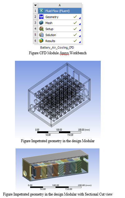
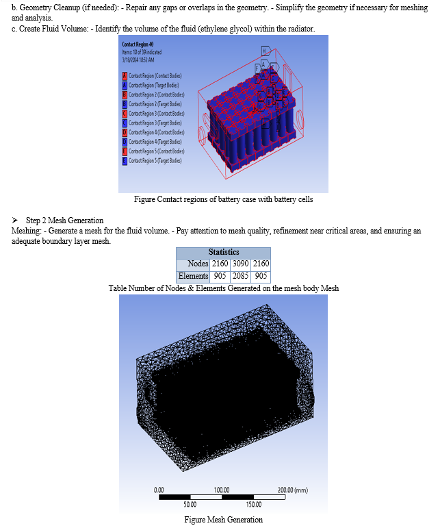
- Step 1 Importation of geometry
Geometry Import: - Import the 3D geometry of the radiator into ANSYS Workbench. - Ensure the geometry is clean and suitable for meshing.
III. DISCUSSION ON THE RESULTS
CFD (Computational Fluid Dynamics) analysis is a powerful tool for simulating and analyzing the performance of various engineering systems, including battery cooling systems. Ansys Workbench, a widely used simulation software package, provides a comprehensive platform for conducting such analyses. In this discussion, we'll delve into the specifics of conducting a CFD analysis of a battery air cooling system using Ansys Workbench, with particular focus on the conditions provided: an initial air temperature of 22 degrees Celsius and an outlet temperature after heat transfer to the lithium battery of 47 degrees Celsius.
Firstly, setting up the simulation involves creating a detailed geometric model of the battery cooling system, including the battery, cooling ducts, inlet and outlet ports, and any other relevant components. This model must accurately represent the physical dimensions and features of the system to ensure realistic simulation results.
Next, boundary conditions need to be defined. In this case, the initial air temperature of 22 degrees Celsius serves as the inlet condition for the cooling airflow. Additionally, the outlet temperature of 47 degrees Celsius after heat transfer to the lithium battery sets the target temperature for the system. These boundary conditions play a crucial role in determining how heat is transferred within the system and ultimately affect its overall performance.
Once the geometry and boundary conditions are set, the simulation can be run using Ansys Workbench. The software solves the governing equations of fluid flow, heat transfer, and possibly other relevant physical phenomena to predict the airflow patterns, temperature distribution, and other key parameters within the cooling system.
During the simulation, various analyses can be performed to gain insights into the system's behavior. For instance, temperature contours can be visualized to identify regions of high heat transfer and potential hotspots within the battery. Velocity vectors can help understand airflow patterns and ensure adequate cooling throughout the system. Additionally, heat transfer coefficients can be calculated to quantify the effectiveness of the cooling process.
After the simulation is complete, the results can be analyzed to assess the system's performance and identify areas for improvement. For example, if the outlet temperature exceeds the desired value of 47 degrees Celsius, adjustments to the cooling duct design or airflow rate may be necessary to achieve the desired cooling effect.
In conclusion, conducting a CFD analysis of a battery air cooling system using Ansys Workbench involves creating a detailed model, defining appropriate boundary conditions, running simulations, and analyzing the results to optimize system performance. By leveraging the capabilities of CFD simulation software, engineers can design more efficient and reliable cooling systems for various applications, including lithium battery cooling
|
Sr No |
Material |
Temperature in Celsius At Inlet |
Temperature in Celsius At Battery |
Heat Flux at battery in w/m^2 |
Velocity in m/sec |
Final Temperature at Outlet in Celsius |
Heat transfer co-efficient in w/m^2-k |
|
1. |
Air – Battery |
22 |
60 |
80 |
0.25 |
40.007 |
25.54 |
Conclusion
The design and development of automatic battery cooling systems using air blowers and temperature sensors represent a critical aspect of enhancing the performance, safety, and longevity of lithium-ion batteries in various applications, including electric vehicles (EVs) and renewable energy storage systems. Through the review of literature and discussion of key findings, several important conclusions can be drawn: Effective thermal management is essential for maintaining optimal battery temperature, preventing thermal degradation, and ensuring safe operation under diverse operating conditions. The literature surveyed emphasizes the critical role of precise thermal regulation in enhancing battery performance, efficiency, and reliability. A wide range of cooling strategies and methodologies have been explored for automatic battery cooling systems, including passive and active cooling methods, phase change materials (PCMs), and advanced cooling designs. Each approach offers unique advantages and challenges, highlighting the importance of selecting appropriate cooling solutions based on specific application requirements and operational constraints. Successful implementation of automatic battery cooling systems relies on seamless integration of air blowers, temperature sensors, control systems, and cooling channels within the battery pack. Optimization of system architecture, component placement, and control algorithms is essential to maximize cooling effectiveness, energy efficiency, and system reliability. Modular cooling system architectures, such as those discussed in the literature, offer scalability, flexibility, and ease of maintenance, enabling tailored thermal management solutions for different battery configurations and EV applications. The modular approach allows for efficient airflow distribution, heat dissipation, and temperature regulation across individual battery modules, mitigating thermal hotspots and improving overall system performance.
References
[1] Lu, H., & Lin, X. (2021). Review on thermal management of lithium-ion battery: Techniques and methodologies. Energy Reports, 7, 375-389. [2] Kim, D. S., Kim, S. H., & Park, J. K. (2019). Battery thermal management system with a modular structure using an air cooling method for electric vehicle applications. Energies, 12(5), 829. [3] Zhang, L., Mao, L., He, Y., Lin, J., & Gao, Y. (2018). An efficient thermal management system for lithium-ion battery packs based on air cooling. Journal of Power Sources, 377, 70-78. [4] Hu, S., Ma, C., Lu, L., & Zhang, W. (2020). A review on thermal management strategies and systems of lithium-ion batteries for electric vehicle applications. Renewable and Sustainable Energy Reviews, 119, 109554. [5] Baronti, F., Fadda, P., Magnani, M., Papini, L., & Spagnolo, M. C. (2016). An overview on lithium-ion battery thermal management systems used in electric vehicle applications. Applied Energy, 179, 375-394. [6] Li, J., Li, X., Guo, H., Li, B., & Yu, J. (2020). A review of active thermal management strategies for lithium-ion batteries in electric vehicle application. Journal of Energy Storage, 30, 101428.
Copyright
Copyright © 2024 Rajendra Ghatode, Bhushan Karamkar, Mahesh Ghorpade, Om Golande, Saurabh Kedar, Pankaj Pawar. This is an open access article distributed under the Creative Commons Attribution License, which permits unrestricted use, distribution, and reproduction in any medium, provided the original work is properly cited.

Download Paper
Paper Id : IJRASET62399
Publish Date : 2024-05-20
ISSN : 2321-9653
Publisher Name : IJRASET
DOI Link : Click Here
 Submit Paper Online

