Ijraset Journal For Research in Applied Science and Engineering Technology
- Home / Ijraset
- On This Page
- Abstract
- Introduction
- Conclusion
- References
- Copyright
Design of Compact Size Tri-Band Stacked Patch Antenna for GPS and IRNSS
Authors: Yash Sarin, Snehil Sachdeva
DOI Link: https://doi.org/10.22214/ijraset.2024.62795
Certificate: View Certificate
Abstract
This paper introduces a low-profile, compact tri-band microstrip patch antenna designed for GPS and IRNSS applications. The proposed antenna operates at frequencies of 1.27 GHz, 2.37 GHz, and 2.79 GHz. The antenna configuration consists of a patch antenna with a slip slot or manderline to generate three frequency bands while maintaining an acceptable radiation pattern. The focus of the study is to enhance the antenna\'s gain across all three frequency bands. This design aims to offer a versatile solution for navigation systems, leveraging the tri-band capability to accommodate different satellite signals and improve overall performance in GPS and IRNSS applications.
Introduction
I. INTRODUCTION
The increasing demand for compact and efficient navigation systems has driven significant advancements in antenna design for satellite navigation applications. GPS and IRNSS are two prominent satellite navigation systems extensively utilized for a wide range of civilian and military applications worldwide. The GPS operates across three primary frequency bands: L1 (1575.42 MHz), L2 (1227.6 MHz), and L5 (1176.45 MHz), while the IRNSS predominantly operates at L5 (1176.45 MHz). Enabling multi-constellation navigation and enhancing system reliability necessitate the development of antennas capable of efficiently covering these frequency bands.
This paper proposes a compact-sized tri-band stacked patch antenna designed to operate across the GPS L1, L2, and L5 bands, and the IRNSS L5 band. By leveraging a stacked configuration, the antenna achieves multi-band operation while minimizing space requirements. The design process entails a comprehensive optimization approach, encompassing patch geometry refinement, substrate material selection, feed network design, and stacked configuration optimization. Through extensive electromagnetic simulations, the antenna's performance is evaluated in terms of impedance matching, radiation efficiency, bandwidth, and radiation pattern characteristics.
II. DESIGN METHODOLOGY
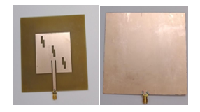
The proposed antenna architecture comprises two stacked patches separated by a dielectric substrate. The top patch is engineered for the higher frequency bands (L1 and L2), while the bottom patch is tailored for the lower frequency bands (L5). A microstrip feed line is employed to connect the patches to the feed network, facilitating efficient power transfer and impedance matching. The design methodology encompasses the following steps:
A. Substrate Material Selection
A dielectric substrate with the appropriate permittivity and loss tangent is carefully selected to attain the desired characteristics of the antenna while ensuring compactness and mechanical durability. The permittivity of the substrate affects the antenna's resonant frequency and impedance matching, crucial for optimizing performance. Additionally, the substrate's loss tangent influences the antenna's efficiency by minimizing signal losses. By choosing a substrate with the right combination of permittivity and loss tangent, the antenna design can achieve its performance goals while meeting size and mechanical requirements. This strategic substrate selection process ensures that the antenna operates effectively while remaining compact and resilient, suitable for various applications and operating conditions.

B. Patch Geometry Optimization
The dimensions of the stacked patches are meticulously optimized using sophisticated electromagnetic simulation software to achieve resonance at the desired frequencies. Parameters such as patch length, width, and substrate thickness are iteratively adjusted to attain optimal impedance matching and radiation characteristics. Through systematic optimization, the antenna design can ensure efficient power transfer and radiation pattern symmetry across the target frequency bands. This iterative process enables fine-tuning of the antenna's geometry to meet performance requirements while maintaining compactness and mechanical robustness. By leveraging advanced simulation tools, designers can expedite the optimization process and accurately predict the antenna's behavior, resulting in a highly efficient and reliable antenna design.
C. Feed Network Design
A microstrip feed line topology is meticulously designed to facilitate efficient power transfer and impedance matching between the feed network and the stacked patches. The dimensions and configuration of the feed network are optimized to minimize losses and enhance the overall performance of the antenna. By carefully adjusting parameters such as line width, length, and substrate properties, designers can achieve precise impedance matching and minimize signal losses along the feed line. This optimized feed network ensures that the antenna receives maximum power from the transmission line while maintaining impedance compatibility with the stacked patches. By prioritizing efficiency and performance in the design of the feed network, the antenna can realize its full potential in terms of radiation characteristics and overall effectiveness in communication or sensing applications..
D. Stacked Configuration Optimization
The separation distance between the stacked patches is carefully optimized to achieve the desired isolation between bands and mitigate mutual coupling effects. Through iterative refinement, the stacked configuration is fine-tuned to enhance antenna efficiency and broaden bandwidth coverage. By adjusting the distance between the patches, designers can minimize interference between adjacent bands and maximize the antenna's performance across its operating frequency range. This iterative process involves evaluating the impact of different separation distances on antenna characteristics such as radiation patterns, impedance matching, and efficiency. Ultimately, by optimizing the stacked configuration, designers can ensure that the antenna delivers optimal performance, with improved bandwidth coverage and reduced mutual coupling effects, making it suitable for a wide range of applications requiring reliable and efficient multi-band communication or sensing capabilities.
E. Radiation Pattern Analysis
Electromagnetic simulations are conducted to meticulously analyze the radiation pattern characteristics of the antenna across all operational bands. These simulations evaluate the radiation patterns for consistency, omni directionality, and gain performance, ensuring reliable reception of navigation signals. By scrutinizing the radiation patterns, designers can verify that the antenna maintains consistent coverage and gain levels across its intended operating bands, essential for robust signal reception from satellite navigation systems. This thorough analysis also confirms the antenna's omnidirectional characteristics, ensuring that it effectively captures signals from satellites distributed across the sky. By leveraging electromagnetic simulations, designers can validate the antenna's performance and make informed adjustments to optimize its radiation patterns, enhancing its suitability for navigation applications requiring precise and dependable signal reception.
III. SIMULATION RESULTS
The proposed antenna design undergoes rigorous electromagnetic simulations to assess its performance across various metrics. The simulation results include:
A. Return Loss
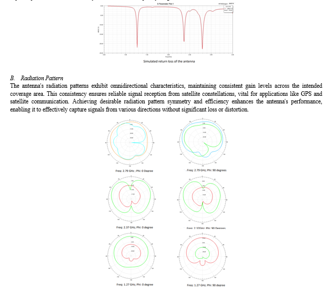
The antenna demonstrates return loss values below -10 dB across all operational bands, signifying outstanding impedance matching and minimal power reflection. This characteristic ensures efficient power transfer between the antenna and the transmission line, maximizing signal transmission and reception performance. With such high levels of impedance matching, the antenna exhibits superior performance and reliability across its entire frequency range.

With such omnidirectional attributes, the antenna ensures robust and dependable communication capabilities, crucial for applications requiring continuous and accurate reception of signals from satellites dispersed across the sky.
C. Bandwidth
The antenna design achieves wide bandwidth coverage across the L1, L2, and L5 GPS bands, as well as the L5 IRNSS band. This expansive coverage ensures comprehensive reception of signals from multiple satellite navigation systems, including GPS and IRNSS. By effectively spanning the desired frequency range with ample margin, the antenna accommodates signal variations and environmental factors. This capability is crucial for maintaining uninterrupted and accurate positioning and navigation capabilities in diverse conditions, making the antenna an optimal choice for applications requiring robust and reliable satellite-based positioning and timing services.
D. Efficiency
The antenna showcases high radiation efficiency, guaranteeing optimal utilization of transmitted power and maximizing the reception capabilities of navigation signals. Through meticulous optimization, the design minimizes losses, thereby enhancing the overall performance of the system. This efficiency is instrumental in ensuring reliable and accurate reception of signals, crucial for applications reliant on precise positioning and navigation, such as GPS-based navigation systems. By prioritizing radiation efficiency, the antenna design enables robust performance, facilitating dependable operation even in challenging environments or under adverse conditions.
IV. MEASURED RESULTS
A. Return loss
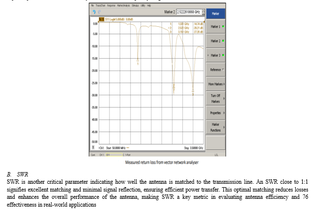
The antenna demonstrates return loss values below -10 dB across all operational bands, signifying outstanding impedance matching and minimal power reflection. This characteristic ensures efficient power transfer between the antenna and the transmission line, maximizing signal transmission and reception performance. With such high levels of impedance matching, the antenna exhibits superior performance and reliability across its entire frequency range.


V. FUTURE DIRECTIONS
Future research endeavors may explore experimental validation of the proposed antenna design to corroborate simulation findings and evaluate real-world performance under varying environmental conditions. Further optimization efforts could focus on refining antenna parameters to enhance efficiency, reduce mutual coupling effects, and extend frequency coverage to additional satellite navigation systems such as GLONASS and Galileo. Additionally, investigations into miniaturization techniques and integration with advanced signal processing algorithms could yield compact yet high-performance antennas suitable for next-generation navigation applications in both civilian and military domains.
Conclusion
In conclusion, the research paper presents a comprehensive design and analysis of a compact size tri-band stacked patch antenna tailored for GPS and IRNSS applications. The proposed antenna design offers a practical solution for achieving multi-band operation while addressing the space constraints associated with compact navigation systems. Through meticulous optimization of patch geometry, substrate material selection, feed network design, and stacked configuration, the antenna demonstrates superior performance in terms of impedance matching, radiation efficiency, bandwidth coverage, and radiation pattern characteristics. The simulation results validate the effectiveness of the proposed design approach in meeting the stringent requirements of satellite navigation applications.
References
[1] Shivam Singh, Dharmendra Kumar and G.S.Tripathi, “Compact Multiband Antenna with Symmetrical I- and S-shaped Slots for Wireless Applications,” in International Conference on Innovations in Information, Embedded and Communication Systems (ICIIECS), 2017. [2] Kevin Geary, James H. Schaffner, Hui-Pin Hsu, Hyok J. Song, Joseph S. Colburn and Eray Yasan, “Single-Feed Dual-Band Stacked Patch Antenna for Orthogonal Circularly Polarized GPS and SDARS Applications,” in IEEE, 978-1-4244-1722-3/$25.00, 2008. [3] Mehre-e-Munir, Ahsan Altaf,andSyed Imran Hussain Shah, “Miniaturization of Multiband Patch Antenna using Stack Configuration,” in IEEE, 978-1-4799-5754-5/14/$26.00, 2014. [4] Mehr-e-Munir and Umar Farooq, “Multiband Microstrip Patch Antenna using DGS for L-Band, S-Band, C-Band and Mobile Applications,” in TCSET, Lviv-Slavske, Ukraine, 2016, pp. 198-201. [5] Farhan. A. Ghaffar, Mohammad Vaseem, Langis Roy and Atif Shamim, “Design and Fabrication of a Frequency and Polarization Reconfigurable Microwave Antenna on a Printed Partially Magnetized Ferrite Substrate,” unpublished. [6] Arumita Biswas and Vibha Rani Gupta, “A Multiband Antenna Design for Long Term Evolution (LTE) Application,” in International Conference on Signal Processing and Communication Engineering Systems (SPACES), 2015, pp. 210-214. [7] Gehan Sami, Mahmoud Mohanna and Mohamed L.Rabeh, “Tri-band microstrip antenna design for wireless communication applications,” in NRIAG Journal of Astronomy and Geophysics, 2013, pp. 39-44. [8] Dhanajay Karkhur, “Review of Techniques to Design Multiband Microstrip Patch Antennas,” in International Journal of Latest Trends in Engineering and Technology (IJLTET), vol. 6, Issue. March 4, 2016, pp. 164-168. [9] Ajay Dadhich, J. K. Deegwal, Sanjeev Yadav, and M.M.Sharma, “Design of Multi-Band Antenna With Cut Slots and Parasitic Patch for Wireless communication,”. [10] U. Chakraborty, A. Kundu, S. K. Chowdhury and A. K. Bhattacharjee “Compact Dual-Band Microstrip Antenna for IEEE 802.11a WLAN Application,” Int. J. Adv. Res. Elect., Electron. Instrum. Eng., vol. 13, 2014, pp. 3273–3280. [11] W. Lin and H. Wong, \"Wideband Circular Polarization Reconfigurable Antenna,\" in IEEE Trans. Ant. Prop., vol. 63, no. 12, 2015, pp. 5938-44
Copyright
Copyright © 2024 Yash Sarin, Snehil Sachdeva. This is an open access article distributed under the Creative Commons Attribution License, which permits unrestricted use, distribution, and reproduction in any medium, provided the original work is properly cited.

Download Paper
Paper Id : IJRASET62795
Publish Date : 2024-05-27
ISSN : 2321-9653
Publisher Name : IJRASET
DOI Link : Click Here
 Submit Paper Online

