Ijraset Journal For Research in Applied Science and Engineering Technology
- Home / Ijraset
- On This Page
- Abstract
- Introduction
- Conclusion
- References
- Copyright
Designing and Modelling of Wind Turbine Simulation Using MATLAB / SIMULINK
Authors: Suman Nalini , M Chinnalal
DOI Link: https://doi.org/10.22214/ijraset.2024.58109
Certificate: View Certificate
Abstract
The renewable energy, Malaysia hopes to lessen its reliance on oil and gas. Wind energy is one of the more promising renewable sources of electricity. Malaysia is situated in an area with low wind speeds, with an annual mean wind speed of 1.2- 4.1 m/s, close to the equator. The northeast monsoon and the southwest monsoon are the two monsoon seasons that Malaysia experiences. While wind speeds during the northeast monsoon can approach 15 m/s, they can only reach 7 m/s during the southwest monsoon season. The potential for wind energy in Sarawak, Malaysia, has only received a limited amount of research and study. In this article, MATLAB/SIMULINK will be used for modelling and simulation of numerous wind energy conversion systems (WESC) utilizing different generators operating under the same conditions in order to analysis the generators\' efficiency. Although ultimately all of them are equally efficient, PMSG has shown to be more efficient than SCIG and DFIG at lower wind speeds. SCIG, DFIG, and PMSG efficiency are, respectively, 66.25%, 69.38%, and 71.88% at the rated wind speed.
Introduction
I. INTRODUCTION
The kinetic energy of the wind is converted into the mechanical energy that turns the rotor blades of a wind turbine, which are connected to a low-speed shaft. This process is carried out by a wind turbine. After that, the mechanical energy will be transferred, with the help of a gearbox, into the high-speed shaft in order for the generator to be able to convert it into electrical energy [1]. Wind turbines with a horizontal axis revolve on an axis that is perpendicular to the direction in which the wind is blowing [2]. If the blades of the wind turbine are spun in such a way that they point in the direction that the wind is blowing, then it is possible to harness the power of the wind. In addition, HAWT often feature towers that are higher, which assists the turbine in meeting the challenges posed by a wind that is stronger. This is since the speed of the wind increases with height, and HAWT towers often have a greater altitude than average. It is feasible to extract the maximum amount of wind energy possible when employing wind turbines that have variable pitch angles. This is accomplished by adjusting the angle at which the blades rotate to either enhance or decrease the amount of power that is created by the wind turbine. Because of this, it is now feasible to harvest the greatest quantity of wind energy that is practicable. Because HAWT models provide more accurate results, we will concentrate our modeling and simulation efforts on those models for the whole of this work. The characteristics of a wind turbine that are most often seen are shown in figure 1.1 below. These are some of the most crucial things to think about while shopping for an ideal turbine, so keep them in mind. The cut-in speed is the minimal wind speed necessary to overcome the friction of the turbine blades and spin the blades. This is the speed at which the blades begin to rotate. This is the speed at which the blades start to revolve after the fan has been turned on. When traveling at this speed, the blades will start to spin in the opposite direction of a clockwise motion. The lowest wind speed at which the turbine can create the power output that is specified for its rating is referred to as the rated speed of the turbine. This is the minimum wind speed at which the turbine is able to generate the power output.
II. CONVERSION WIND ENERGY SYSTEM
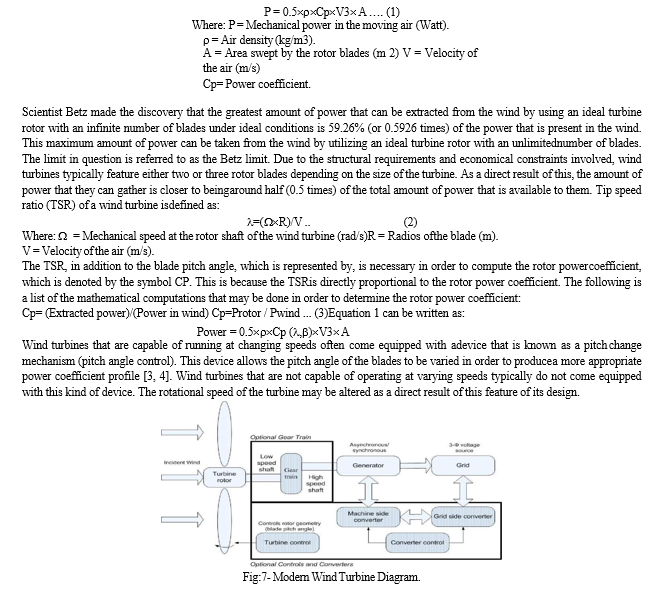
In order to generate mechanical energy, a wind energy conversion system, more often referred to as a WECS, is propelled by the force of the wind. After that, this kind of mechanical energy is transferred to an electrical generator so that it may be used in the process of producing electricity. The connection that can be made with a WECS is shown in figure 1.3. It is possible that the generator of the wind turbine is a permanent magnet synchronous generator (PMSG), a doubly fed induction generator, an induction generator, a synchronous generator, or one of the many alternative designs that are feasible. The wind energy that is collected by the wind turbine and used by the generator is what makes up the source of the electricity. The WECS makes use of a pulse width modulation converter in order to keep the spinning speed of the generator at the optimal level so that it may produce the most amount of power that is technically possible.
The electricity that is produced by the generator is sent into the grid by means of an inverter that is located on the side of the grid and a converter that is located on the side of the generator. Both devices are connected to each other through cables. Wind farms may be in a wide variety of environments, some of which include onshore, offshore, hilly terrain, and coastal locations. It is possible that the WECS DG may end up being the most important one in the not-too-distant future. This is something that can be expected to happen.

Wind power is an alternative to the use of fossil fuels because it does not produce any emissions while it is functioning; it only requires a very small amount of land; it is abundant; it is renewable; it is widely scattered; it is clean; it is affordable; it is abundant; it is widely dispersed; it is clean; it is inexpensive; it is an alternative to the use of fossil fuels [14]. In general, the impacts on the environment are of far less concern than the problems that are caused by other traditional sources of electricity. The fluctuating wind speed causes the wind energy conversion system's output power to vary, which in turn has the potential to cause the frequency of the power grid to diverge in an unexpected way. Already, a sizeable amount of investigation has been carried out in the pursuit of finding a resolution to this issue in the not-too- distant future. The main data that was used for the 2013 edition of the World Wind Energy Report was gathered by an organization known as the World Wind Energy Association (WWEA). The global capacity for wind energy reached 318.5 GW at the end of 2013, which is an increase above the capacity of 282.2 GW that was reached in the previous year. There are now 103 nations throughout the world that allow the commercial use of wind power in some capacity. With a total capacity of 91.3 GW and a new capacity of 16 GW, China has retained its position as the most important participant in the worldwide wind industry.
A. Wind Turbine
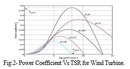
There is a chance that the HAWT market might be further subdivided into wind turbines that operate at fixed speeds and wind turbines that operate at variable speeds [7]. This is an extra possibility that may be pursued. For one of the wind turbines to be able to keep its speed consistent while it is operating, it is equipped with a component known as a squirrel cage induction generator, or SCIG for short. A wind turbine that has a speed that can be altered will always have the same rotational speed for its rotor, regardless of how quickly the wind is blowing. This is because of the speed's ability to be adjusted. This is because the pace may be adjusted. It is reliant on a variety of various elements, some of which include the frequency of the grid, the gear ratio, and the design of the generator.
B. Generator
One might further subdivide the term "electric generator" into "asynchronous generator" and "synchronous generator." These two categories of generators are both capable of producing electrical current. The most important distinction between the two is that synchronous generators do not need the power supply from the grid in order to excite their windings, in contrast to asynchronous generators, which do require the power supply from the grid in order to excite their windings. This is the most significant difference between the two types of generators. This is the primary point of distinction between the two distinct varieties of generators. This distinction between the two types of generators is the more significant of the two.
Synchronous generators, on the other hand, do not need the power source that is supplied by the grid in order to excite the windings of their machines. Synchronous generators can achieve this without the grid's assistance. The low rotational speed of the turbine blades must be increased by the gearbox to the greater rotating speed of the rotor shaft before the turbine can fulfill the duties for which it was designed. Because of this, the generator is now able to accept power from the turbine. This came about as a direct result of the previous sentence.

III. DOUBLY FED INDUCTION GENERATOR
Doubly fed induction generator (DFIG), which is receiving a growing amount of interest for applications that need power in the range of megawatts [13], is one solution. The windings onboth the stator and the rotor of this generator are set up in a three-phase arrangement, which is whythe generator is referred to as a three-phase device. After the rotor, the stator windings, and the back-to-back converters have been connected to the grid, it is the responsibility of the back-to- back converters to regulate the speed of the rotor. The grid will provide an electrical current that will excite the rotor windings, and the magnetic field that will be created by the rotor windings will revolve in time with the blades of the rotating turbine. This will be accomplished by the rotorwindings. Alternating current will be produced because of the interaction between the revolving magnetic flux and the stator windings in an electric generator. This interaction will produce alternating current.
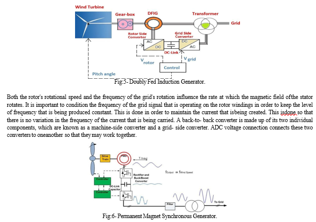
This effect is created by the wind turbine. One can achieve this objective by following thestrategy described in the previous paragraph. The presentation of the PMSG wind turbine model that is shown here in figure 3.7 should provide for an enjoyable viewing experience for you. The fact that modern computers have a basic organizational framework is one of the key reasons that has led to the widespread usage of these machines. [Case in point:] [C]computers have a fundamental organizational framework. Since the brushes, sliprings, and commutators of a WRSGare held in place by permanent magnets, disassembling and removing these components from theWRSG may be accomplished with relative ease. Disassembling a WRSG needs permanent magnets. This task may be completed in its entirety if one so chooses. As a result of this, the system's level of dependability will considerably increase, and as a direct consequence of this, it will become an alternative to the WRSG that is, in some circumstances, preferable. A PMSG's overall design must have both a rectifier and an inverter for the device to perform as intended whenput into operation. This is because the PMSG is a generator with variable speed.
IV. MODELING OF WIND TURBINE
An example of this would be a wind turbine, which is a piece of technology that converts the kinetic energyprovided by the wind into electrical energy. The rotor is one of the three primarycomponents that come together to produce the overall system that is the wind turbine. The bladesthat areresponsible for transforming thehigh-velocitywind energyinto a lower-velocity rotationalenergy are housed inside this component. The generator is the third and final component of the system. The second component is known as the generator, and it is made up of an electrical generator in addition to all the control circuits and gears that are necessary to convert the low- speed rotation into electric power. This second component is referred to as the generator. The structure is the very final part of the generator, and it is responsible for housing all the earlier partsinside its own boundaries. This structure, which consists of the tower as well as the nacelle, is thecomponent that brings the generator to its final form.
There are essentially two different types of wind turbines, and the distinction between the two is based on the axis that the machine revolves around. One may make a distinction between a horizontal axis and a vertical axis when they are contained inside it.
There is a consensus among experts that wind turbines with a horizontal axis are more prevalent and ubiquitous in comparison to wind turbines with a vertical axis [1]. Wind energy may be harnessed and converted into usable forms of power via the use of adevice called a wind turbine. Wind power generation is the term used to describe this process. The following equation demonstrates how the air density, power coefficient, air density, and turbine swept area are all elements that impact the total amount of energythat is collected from the wind:
Wind turbines that can run at changing speeds often come equipped with adevice that is known as a pitch change mechanism (pitch angle control). This device allows the pitch angle of the blades to be varied in order to produce a more appropriate power coefficient profile [3, 4]. Wind turbines that are not capable of operating at varying speeds typically do not come equipped with this kind of device. The rotational speed of the turbine may be altered as a direct result of this feature of its design.
V. RESULT AND ANALYSIS
The wind turbine generator is the most important component of a wind turbine (WT) system since it is the component that is accountable for transforming the mechanical energy that is produced by the turbine into electrical energy. Most of the time, problems that occur with windturbines are due to components in the generator being damaged in some way. As a direct result ofthis, the analysis of the generator model in wind turbines is developing into a subject of research that is becoming more important. This is because, in order to avoid problems with wind turbines,it is vital to be aware of the special attributes of the generator. The objective of this study is to construct a mathematical model of a generator that can easily be adjusted to account for any faultthat may occur in the generator. This research will be used to conduct research on WT dynamic systems, and the goal of this study is to contribute to that research. The primary objective of this line of study is going to be the formulation of a mathematical model of a generator that is appropriate for implementation in wind turbines. This is a result of the fact that the most of the WT models that have been developed up to this point either include protection for intellectual property or are relatively straightforward in the generator modeling that theyuse. Both MATLAB and Simulink were used throughout the whole of the process of constructing the mathematical model of the wind turbine-based induction generator for the purpose of this project. The model of a wind turbine that was built includes not only an aerodynamic model but also a model of an induction generator and a drive train for the wind turbine that is based on a model with two masses. The construction of the induction generator was based on electrical equations that were arranged inside Park's reference system. The building of the model incorporates not just one but two distinct subsystems: a mechanical one and an electrical one. Thesuggested model of the wind turbine fitted with an induction generator was verified by means of aMATLAB software simulation of a wind farm fitted with a detailed model of a doubly-fed induction generator (DFIG).
???????A. Methodology Of The Wind Turbine
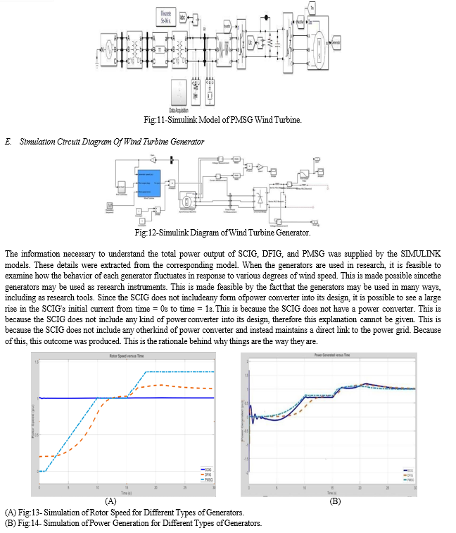
With several simulations, we are going to present several distinct WECS in this part. The following building pieces are utilized to construct the simulation's portrayal of the wind speed, asseen in Figure 8. The modeling of the simulation will be done using these pieces. Between the timet = 1 second and t = 10 seconds, the speed of the wind is going to grow from a speed of 0 meters per second to a speed of 9 meters per second. This increase is going to take place. After t = 15 seconds, it will then begin to raise its speed to 15 meters per second, having previously been at 9 meters per second. This will take place after the initial speed of 9 meters per second has been maintained.
Up until the time equals thirty seconds, there is not going to be any change at all in the speed of the wind. This simulation's goal is to investigate the performance of a variety of generators when subjectedto three distinct levels of wind speed: 0 meters per second (the "zero wind speed" condition), 9 meters per second (the "base wind speed"), and wind speeds that are greater than the "rated wind speed." All these aspects are evaluated, including the apparent power, the apparent reactive power,the rotor speed, the mechanical torque, and the pitch angle. Measurements are taken, and records are kept. The actual power output, the rotor speed, and the pitch angle are all aspects of the wind turbine that will be the subject of conversation.

B. SCIG Wind Turbine
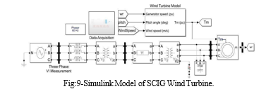
Figure :9 provides a visual representation of the modeled SCIG wind turbine that was created using SIMULINK. Together with the 30-kilometer transmission line, the 575V/25kV step-up transformer and the 25kV/120kV step-up transformer make it possible for the 1.5 MW inductiongenerator to be directly connected to the power grid. We will be using the SIMULINK model of the wind turbine in order to offer the required quantity of mechanical torque for moving the rotorof the generator. After SCIG has transformed the mechanical torque into electrical power, that power will be delivered to the grid through the stator windings. The VI-measurement blocks are going to take readings of the voltage, current, active power, and reactive power.
C. DFIG Wind Turbine
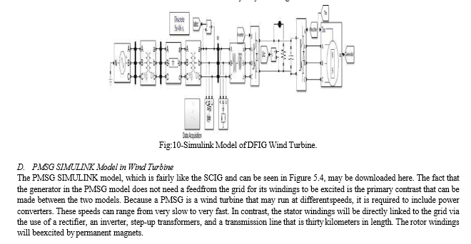
Figure 10 presents a DFIG model that is quite comparable to the SCIG model. This comparison may be seen by comparing the two models. The sole difference between the two models is the way in which step-up transformers and power converters link the rotor windings of the DFIG type to the grid. This is the only difference between the two versions. Transformers areused so that a connection may be made between the stator windings and the grid of the power supply. Because there is no other source, the reactive power that is necessary to activate the generator stator will be drawn from the grid. This is because the grid is the onlysource that is nowaccessible. When a rectifier and an inverter are placed inside of a universal bridge, the process ofmodeling a DFIG wind turbine is said to be complete.
The total number of components is now upto four as a result of this. After first converting the fluctuating AC electrical power that is producedinto stable DC power with the help of a rectifier, the DC power will then be transformed back into AC electrical power with the assistance of an inverter. While the rectifier control system overseesdetermining the speed at which the generator spins, the inverter control system oversees controlling the amount of electricity that is sent out to the grid. Alternating current will be produced as a direct result of the interaction between the spinning magnetic flux and the stator windings of the generator. This will take place as a direct consequence of the interaction. Both the rotor's rotational speed and the frequency of the grid's rotation influence the rate at which the magnetic field of the stator rotates. It is important to condition the frequency of the grid signal that is operating on the rotor windings in order to keep the level of frequencythat is being produced constant. This is done in order to maintain the currentthat is being created. This is done so that there is no variation in the frequency of the current that is being carried. A back-to-back converter is made up of its two individual components, which areknown as a machine-side converter and a grid-side converter. A DC voltage connection connectsthese two converters to one another so that they may work together.
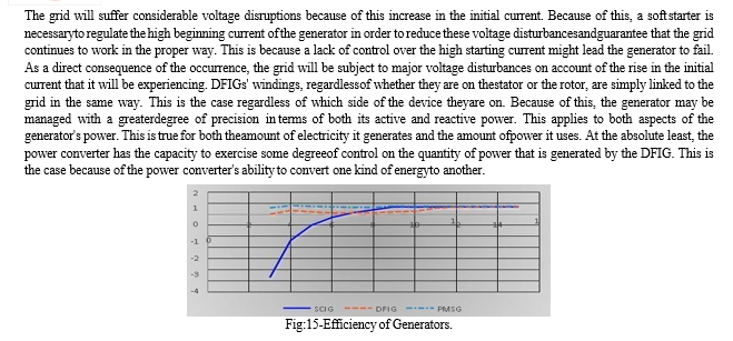
The number of particles per unit area in the atmosphere, with A referring to the entire surface area that is covered by the rotor and v referring to the speed at which the air is traveling. If we proceed with the evaluation of the generator based on the presumption that the pitch controller will be engaged as soon as t = 15 s, then we will be able to evaluate its performance upto that time. if the actual wind speed reaches a level that is greater than the wind speed that the sailwas designed to withstand. The data on efficiency that was collected between t = 0s and t = 3s hadto be excluded from the research since SCIG experiences a current spike during those times because it is directly coupled to the power grid and does not have a soft starter installed. This meant that the data could not be included in the study. Because of the dynamics of the circumstance, it was imperative that this be done. The SCIG will draw electricity from the grid during the intervals of time ranging from t = 3s to t = 7s in order to excite the windings in advanceof the beginning of the generator's process of manufacturing energy. This will allow the windingsto be excited in preparation for the beginning of the process. This will occur between the periods of t = 3s and t = 7s, inclusive. This sheds light on the factors that contribute to the generator's lowefficiency rating, which was previously unknown to me.
Conclusion
Up to this moment, effective simulations of the SCIG, DFIG, and PMSG wind turbines\' SIMULINK models have been carried out within the limitations of the restrictions imposed by thisresearch project. When contrasted with variable-speed wind turbines that employ DFIG and PMSG, the structure of an SGIG turbine is a great deal simpler and much simpler to grasp. On theother hand, variable-speed generators provide a variety of advantages that fixed-speed generatorsdo not have, including a higher level of reliability and overall efficiency. Even though all of themeventually reach the same level of efficiency, the simulation that was run indicated that PMSG is more efficient than SCIG and DFIG even when the wind speed is low. This was the case even though all of them eventually attain the same level of efficiency. This is the case regardless of whether all of them finally attain the same level of productivity. The fact that they each finally reach the same degree of efficiency does not alter the fact that this continues to be the case even ifit may seem like it should change. In a wind turbine, the kinetic energyof the wind is transformed into the mechanical energythat is required to spin the rotor blades, which are attached to a low-speed shaft. This operation is often carried out using a wind turbine. This is how the wind\'s kinetic energy is converted into usable electrical energy. After that, the gearbox will be used to transmit the mechanical energy intothe high-speed shaft so that it may be converted into electrical energy by the generator [1]. After the preceding stage has been finished, we shall go on to the next one. Wind turbines with a horizontal axis revolve around an axis that is perpendicular to the direction in which the wind is flowing [2, 3]. It will be able to harness the power that is provided by the wind if the rotors are positioned in such a manner that they face in the direction that the wind is blowing. In addition, HAWT often includes towers that are taller, which helps the turbine to better combat a greater wind. This is one of the advantages of using HAWT.
References
[1] Saberi, Z., A. Fudholi, and K. Sopian, Fitting of Weibull Distribution Method to Analysis Wind Energy Potential at Kuala Terengganu, Malaysia. Journal of Advanced Research in Fluid Mechanics and Thermal Sciences, 2020. 69: p. 13-22. [2] Yahyaoui, I. and A.S. Cantero, Chapter 16 - Modeling and Characterization of a Wind Turbine Emulator, in Advances in Renewable Energies and Power Technologies, I. Yahyaoui, Editor.2018. [3] A.R, S., et al., Numerical study of effect of pitch angle on performance characteristics of aHAWT. Engineering Science and Technology, an International Journal, 2016. [4] Katsigiannis, Y. and G. Stavrakakis, Estimation of wind energy production in various sitesin Australia for different wind turbine classes: A comparative technical and economic assessment.Renewable Energy, 2014. [5] Islam, M.R., Y. Guo, and J.G. Zhu, Power converters for wind turbines: Current and futuredevelopment. 2013. [6] Funabashi, T., Chapter 1 - Introduction, in Integration of Distributed Energy Resources in Power Systems, T. Funabashi, Editor. 2016. [7] Sumathi, S., L. Ashok Kumar, and P. Surekha, Wind Energy Conversion Systems, in SolarPV and Wind Energy Conversion Systems: An Introduction to Theory, Modeling with MATLAB/SIMULINK, and the Role of Soft Computing Techniques, S. Sumathi, L. Ashok Kumar,and P. Surekha, Editors. 2015. [8] Mali, S., S. James, and I. Tank, Improving Low Voltage Ride-through Capabilities for GridConnected Wind Turbine Generator. Energy Procedia, 2014. [9] Laakam, M., D. Mehdi, and S. Lassaad, Study of induction generator isolated mode. International Journal of Research in Engineering & Advanced Technology IJARET, 2014. [10] Rawal, C.S. and A.M. Mulla, An AC-AC converter for doubly fed induction generatordriven ByWind Turbine.2016. [11] Zou, Y., Induction generator in wind power systems, in Induction Motors-Applications,Control and Fault Diagnostics. 2015. [12] Shewale, A.J., A.R. Gagangras, and N.M. Lokhande, Comparison of various Wind TurbineGenerators.2018. [13] Jadhav, H.T. and R. Roy, A comprehensive review on the grid integration of doubly fedinduction generator. International Journal of Electrical Power & Energy Systems, 2013. [14] Calderaro, V., et al., Design and implementation of a fuzzy controller for wind generatorsperformance optimisation. 2007. [15] Esterhuizen, R., Comparative Study between Synchronous Generator and Doubly-FedInductionGenerator in Wind Energy Conversion Systems. 2019.
Copyright
Copyright © 2024 Suman Nalini , M Chinnalal . This is an open access article distributed under the Creative Commons Attribution License, which permits unrestricted use, distribution, and reproduction in any medium, provided the original work is properly cited.

Download Paper
Paper Id : IJRASET58109
Publish Date : 2024-01-19
ISSN : 2321-9653
Publisher Name : IJRASET
DOI Link : Click Here
 Submit Paper Online

