Ijraset Journal For Research in Applied Science and Engineering Technology
- Home / Ijraset
- On This Page
- Abstract
- Introduction
- Conclusion
- References
- Copyright
Designing Microstrip Low-Pass Filter with Cutoff Frequency 3GHz
Authors: Abobkr H. R. Mohamed, Saleman A. A Abobker
DOI Link: https://doi.org/10.22214/ijraset.2024.64383
Certificate: View Certificate
Abstract
The aliasing phenomenon became a problem in communication systems when an input signal includes high frequency components. These higher frequencies can fold on the lower frequency spectrum and appear as erroneous signals that cannot be distinguished from valid sampled data. Therefore, will design low-pass filter with cut-off frequency 3GHz using Microstrip technique which will work to remove and reject these high frequencies, in addition to microstrip technique, would be design low-pass filter using lumped elements to make comparison between them. There are two methods which can used to design Microwave Filters, the first method is Image parameters and the second is Insertion Loss method. These methods will explain. RF and microwave filters may be designed as lumped element or distributed element circuits; they may be realized in various transmission line structures, such as waveguide, coaxial line, and microstrip. In practice, high-performance microwave filters with minimized size and weight are playing an important role for design and fabrication of high-efficiency miniaturized microwave systems. Software simulation is done by using Microwave Office V.6.4 software, Graphs, and Electronics circuits will be presented.
Introduction
I. INTRODUCTION
Filters have significant functions in many RF/microwave applications. They can be used to separate or merge diverse frequencies and they also can be applied with software running on a general purpose computer; therefore, they are comparatively easy to build and test. Filters can be used to choose or confine the RF/microwave signals in allocated spectral limits. Emerging applications such as, wireless communications go on to confront RF/microwave filters by ever more strict requirements higher performance, lighter weight, lower cost, and smaller size. There are two general motivations for filters, one is to improve the quality of the input, and the other is to process information from the input. Depending on the requirements and stipulation, RF/microwave filters can be designed as lumped element or distributed element circuits; they might be recognized in different transmission line structures, such as passive electronics, active electronics, waveguide, coaxial line, and microstrip. A lumped element includes separate elements, such as inductors and capacitors, whereas distributed element utilizes the lengths and widths of transmission lines to produce their inductive or capacitive values. The Lumped elements are too small compared with the wavelength, while distributed elements are often in the order of the wavelength. Most of these techniques depend on the ability to manipulate the frequency scale, in addition to the ability to handle the power and the order of the filter. RF and Microwave filters can be implemented with transmission lines. Transmission line filters can be easy to implement, depending on the kind of transmission lines that are used.
Microwave filters are two-port system used to control the frequency response at a sure point in microwave systems. At high frequencies ten GHz or higher the wavelength is too short that only distributed elements are possible to practically realize, though at low frequencies lumped elements are used due to the fact that distributed elements becomes too large. In particular, low pass filters allow to lower frequency components to pass into the signal; whereas, reject the higher frequency components. Low pass filters are commonly used in different electronic devices to cut off interference from the surrounding environments.
In modern microwave communication systems the microstrip filters became necessary components, particularly in mobile communications and satellites. With the current growth of the wireless communication manufacture, the requirements for high performance filters are growing rapidly. In modern studies, the compact size and harmonic repression for the low pass filter structures are two significant factors in their design. Compact structures at high frequencies should give high-quality performance, large reject band between the first and the second harmonics and a good suppress of secondary harmonics.
II. OBJECTIVES
The main goal of this study is to design low-pass filter using microstrip technique, which will work to reduce and remove noise, which caused by interference high frequencies that became a problem in the mobile communications systems. The low pass filter will design at cutoff frequency 3.0GHz, which will be suitable for some applications of the mobile communications such as GSM900, GSM1800 and UMTS.
III. BRIEF HISTORY OF RF AND MICROWAVE WIRELESS SYSTEMS
The wireless systems era was started by two scientists in 1864. (James clerk Maxwell and Heinrich Rudolf Hertz). Maxwell presented Maxwell’s equations by uniting the works of Lorentz, Faraday, Amperes, and Gauss. Where predicted the propagation of electromagnetic waves in free space at the speed of light, and postulated that light was an electromagnetic phenomenon of a particular wavelength. His theory had not been accepted for more than two decades; in 1887 Hertz discovered the electromagnetic wireless wave propagation. Hertz demonstrated radio frequency (RF) generation propagation and reception in the laboratory. His radio system exponent coasted of an end-loaded dipole transmitter and a resonant square-loop antenna receiver operating at a wavelength of 4m. For this works Hertz is known as the father of radio, and frequency is described units of Hertz (Hz). Hertz remained working in the laboratory for about two decades; even 1897 Marconi envisioned a method for transmitting and receiving information. Where sent the first wireless communication over water, where the message at that time was “Are you ready?” and allowed the transfer of information from one continent to another without a physical connection. After that, the telegraph became the means of fast communications [1, 2].
In the near beginning of 1990s, for the most part the wireless transmission happened on very long wavelengths. The continuous waves (CW) changed spark gaps, and more dependable frequency and power output were attained for radio broadcasting at frequencies below 1.5MHz., in the 1920s the one-way broadcast was made to police cars in Detroit, and then the use of radio waves for wireless broadcasting, communications between mobile and land stations, public safety system, maritime mobile services, and land transportation systems was significantly increased. In 1934, AM mobile communication systems were used for police in the US. Through World War II, the technology of radio was greatly improved, and therefore the radio communications became necessary for military use in theatres of war and troop maneuvering, and also during the World War II, created urgent need radar which is standing for radio detection and range. Since that time the acronym radar became a common term, which is describing the use of reflection from objects to detect and determine the distance and relative speed for the target. Radar designed to recognize the minimum object size that can be detected from through proportional wavelength. Therefore, shorter wavelength or higher frequencies (microwave frequencies and above) are required to detect smaller objects such as fighter aircraft [3, 4].
The wireless communications systems using telegraphs, broadcasting, telephones, and point to point radio links were available before World War II by Guglielmo Marconi. which was opened the way for the modern wireless communications systems by sending the three-dot Morse code for the letter ‘S’ over a distance of three kilometers by electromagnetic waves. Thereafter, wireless communications system has developed into a key element of modern society. The widespread use of communications methods was accelerating during and after the war. For long-distance wireless communications, relay system or troposphere dispersing were used. In 1959, J.R. Pierce and R. Kompfner envisaged transoceanic communications by satellites. This opened an era of worldwide communications using satellites. The satellite uses a broadband high frequency system that can support thousands of telephone users concurrently, and also hundreds or more of televisions channels, and a lot of data links. The frequencies are working in the GHZ range. In 1990s, wireless communication devices and mobile phones became popular and grew very rapidly in the past two decades. The personal communication systems such as laptop are working at higher frequencies with wider bandwidths which are emerging with a combination of diverse services such as voice mail, email, video, messaging, data, and computer on-line services. Today the direct line between satellites and personal communication systems became provide voice and video, or data communication at anywhere in the globe, even in the remote areas of the world [6, 7].
In addition to communication and radar application, wireless technologies have many other applications. Wireless technology allows network managers to organize or connect the networks without fixing or moving wires, today almost all computing devices including desktops, workstations, monitors, keyboards, notebooks, handhelds and printers, became equipped to communicate wirelessly. The use of wireless RF and microwave technologies for motor vehicles and highway applications has increased during the past two decades, especially in Europe. With over 160 million mobile experts worldwide, organizations utilize wireless technologies to solve business problems and create benefits over competitors. Mobile professionals utilize this new benefit to work more effectively, better satisfy customers, and produce more sales. The direct broadcast satellite (DBS) systems have offered an ersatz to cable television, and the end of the Cold War has made many military technologies available to civilian applications.
The global positioning systems (GPS), RF identification (RFID) systems, and remote sensing and surveillance systems have also found many commercial applications. There are many advantages of wireless technology: Simple-to-use, more secure Reduce costs and Improve performance [8].
IV. WIRELESS AND RF APPLICATIONS
There are many applications of RF microwave. The important of these applications are communication systems and radar. However, there are many other applications such as PCSs and cellular phones, which currently have phenomenal growth in the markets. While, there is also an increased demand for satellites, and data communication systems. The Radio waves and microwaves play significant role in modern life. For example, Aircrafts movement are guided from takeoff to landing by microwave radar and navigation systems, Television signals are transmitted around the world by satellites using microwaves, Telephones and data signals are transmitted using microwave relays[9]. The military uses microwaves for surveillance, navigation, control and guidance, communications, and identification in their tanks, planes and ships. Cellular telephones are using microwaves everywhere.
Microwave wireless technologies and RF have many applications in the domains of military, civilian and commercial. Where these application include communications, radar, navigation, remote sensing, RF identification, broadcasting, sensors, surveillance, medical, and astronomy and space exploration. In recent years, the high-gain wideband directional antennas has increased in wireless applications, such as WLAN and LMDS; particularly, world interoperability for microwave access (WiMax), a technology founded on an growing standard for broadband point-to-multipoint wireless networking ,and which became an important point in the wireless manufacture. For other wireless applications; for example, wireless power transmission which is also wanted to use a circularly polarized (CP) antenna to avert the power loss that caused by an unexpected rotation of transmit or receive antennas [10 and 11]. And the short backfire antenna (SBA) might become one of the most requested techniques for wireless applications that depend on its high gain and simple structure, where the most common excitation for the SBA is a simple dipole antenna but the dipole-excited SBA has a narrow bandwidth for its input impedance. The low-cost wideband SBA are developed for wireless applications and it is excited by a planar monopole that printed on the same dielectric substrate with its feeding microstrip line. This pattern is useful in reducing the industrialization cost.
V. SIMPLE EXAMPLE OF WIRELESS RADIO SYSTEM
Figure (1.2) shows a simple example of wireless radio system, the wireless system is consist of active and passive devices interconnected to perform a useful function. The transmitter works by input base band signal, which might be voice, video, or data, which is supposed to be band limited to a frequency FM.This signal is filtered to remove any components that might be beyond the channel’s pass band. Then the massage signal is mixed with a local oscillator signal to create a modulate carrier in a process called up-transfer because it produces signals at frequencies (FLO + FM) or (FLO - FM) which are usually much higher than FM. After that the modulated carrier can be amplified and sent out by the antenna. When the signal enters at the receiver, be improved and amplified by a low-noisy amplifier (LNA). When the received signal has enough power to be mixed directly, as may occur in short-distance communication links, the LAN might be omitted from some systems.
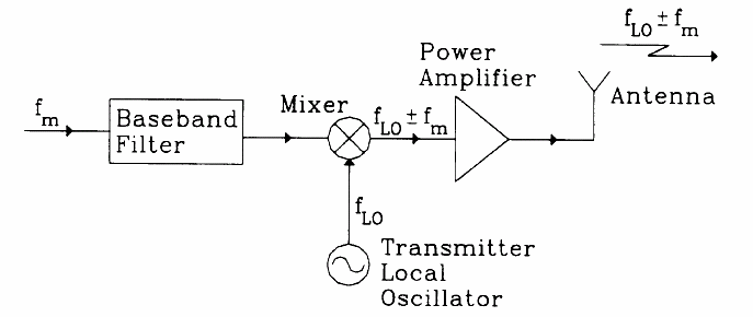
Fig 1: Transmitter
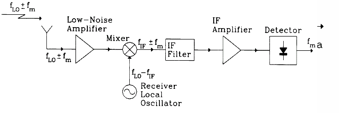
Fig 2: Receiver
The mixer produces a signal at frequency (FLO + FM) or (FLO - FM) in process called down-conversion because FIF is selected to be much lower than FL. The signal is filtered to remove any unwanted harmonic and false products resolution from the mixing process and is amplified by an intermediate-frequency (IF) amplifier. The output of the amplifier transfers to a detector stage where the base band signal FM, which is include the original message. To achieve all of these functions, the microwave system depends on separate components that give specific function to the overall system performance. Generally the microwave components can be classified as transmission lines, couplers, filters, signal control components, amplifiers, oscillators, mixers, detectors, and antennas.
VI. MICROSTRIP FILTER DESIGN AND SIMULATION
To the microstrip filter design is followed by insertion loss method for designing a low-pass filter and stepped impedance low-pass filter. Then design a low-pass filter using microstrip technique, in addition to design the low-pass filter was using lumped elements to compare between both designs.’
A. Microwave Filters can be designed by using two methods:
1) Image parameters method:
The image parameter method is useful to design and study filters and also in solid state traveling wave amplifier design, the filter designed by image parameters method comprise series of simpler two- port filter parts to give the required cutoff frequencies and reduction characteristics, but don’t allow the requirements at of a frequency response over the complete operation range, Thus, despite the procedure relativity simple, the design of filter by this method often should be repeated more times to reach to the required results.
2) Insertion Loss method:
The insertion loss method allocates a high degree of control over the stop-band amplitude and phase characteristics, with an organized way to synthesize a required response. where it is more modern than image parameters method, This Method uses networks by synthesis systems to design filter with completely specific frequency response, The design is easy by starting with low-pass filter prototype that are normalized in terms of impedance frequency, then transformations are applied to transfer the prototype design to required frequency range and impedance level.
VII. DESIGN LOW-PASS FILTER USING INSERTION LOSS METHOD
Generally, the design of micro-strip low-pass filters includes two main steps:
A. Select an appropriate low-pass prototype
The choice of the type of response, including pass-band ripple and the number of reactive elements, will depend on the required specifications. The element values of the low-pass prototype filter, which are usually normalized to make a source impedance g0=1 and a cutoff frequency fc=3 GHz, are then transformed to the L-C elements for the desired cutoff frequency and the desired source impedance, which is normally 50 ohms for microstrip filters, Having obtained a suitable lumped-element filter design.
B. Finding an appropriate microstrip realization
The insertion method might be utilized to characterize a filter response in microwave. It is defined as the ratio of power available from power delivered to load. The most two common types of filter characteristics are used maximally flat and Chebyshev filters.

Fig3: The process of Filter design by the insertion Loss
C. Stepped-Impedance Low-pass Filters:
The figure 4 below illustrates a general structure of the stepped-impedance low-pass microstrip filters, which use a cascaded structure of alternating high- and low impedance transmission lines. These are much shorter than the associated guided- wavelength, so as to act as semi lumped elements. The high-impedance lines act as sequence inductors and the low-impedance lines act as shunt capacitors. Therefore, this filter structure is directly realizing the L-C ladder type of lowpass filters of figure 5. Some a priori design information must be provided about the microstrip lines, because expressions for inductance and capacitance depend upon both characteristic impedance and length. It would be practical to initially fix the characteristic impedances of high and low-impedance lines by consideration of:
Zoc ? Zo ? Zol where Zoc and Zol indicate to the characteristic impedances of the low and high impedance lines, respectively, and Zo is the source impedance, which is usually 50 ohms for microstrip filters.
A lower Zoc result in a better approximation of a lumped-element capacitor, but the resulting line width ωc must not allow any transverse resonance to occur at operation frequencies. And a higher Zol leads to a better approximation of a lumped-element inductor, but Zol must not be so high that its fabrication becomes inordinately difficult as a narrow line, or its current-carrying capability becomes a limitation.
Where:
Zoc is the highest practical line impedance.
Zol is the lowest practical line impedance.

Fig 4: General structure of the stepped-impedance low-pass microstrip filters.

Fig 5: L-C ladder type of low-pass filters to be approximated.
Design Stepped Impedance low-pass Filter having maximally flat response and cut off frequency and insertion loss more than 20dB at frequency 5.0GHz. The filter impedance is 50 ohm the highest practical line impedance is 120 ohm and lowest is 20 ohm.
D. Design Low-pass Filter Using Microstrip:
In order to illustrate the design procedure for this type of filter, the design of a low-pass filter using maximally flat (Butterworth) response is described in follows:
The specifications for the filter under consideration are N (Number of elements or the order of the filter) is given below:
From the graph below at attenuation more than 20 dB, can be find the value of N (N=6)
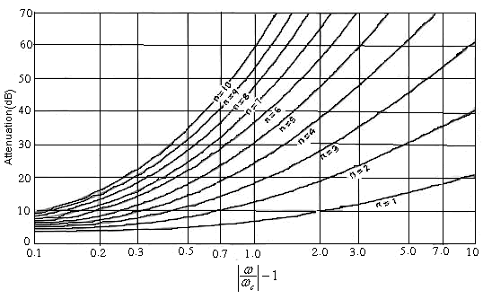
Fig 6: Attenuation vs. normalized frequency for maximally flat (Butterworth) filter prototypes
Cutoff frequency fc= 3GHz
Insertion Loss of 20dB at frequency f = 5.0 GHz
Source/load impedance Zo = 50 ohms
Zh: (Highest practical line impedance) = 120 ohms.
ZL: (Lowest practical line impedance) = 20 ohms.
A low-pass prototype with maximally flat (Butterworth) response is chosen, whose element values are taken from this table at N = 6.
Table 1 Element values for maximally flat (Butterworth) low-pass prototype filters
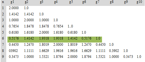
The figures (7, 8 and 9) below depict the equivalent circuit of low-pass filter of sixth order, Stepped impedance implementation and final layout of microstrip.

Fig 7: Low-pass Filter prototype circuit (The order of Filter = 6)

Fig 8: Stepped - impedance implementation ( N = 6)

Fig 9: Microstrip Layout of Final Filter
E. Calculation and Simulation Results:
For normalized cut off frequency fc= 3 GHz, and use the electrical length of the elements:
(For Inductor) ………………………………. (1)
(For Capacitor)……………………………. (2)
Where:
: the Filter impedance or
= 50 ohm.
L and C are the normalized elements values of the Low-pass prototype.
From the Microstrip guide wavelength as a function of w/h and , can be find the microstrip physical line width (w), where are
and h = 1.6 mm at:
|
|
When Zh =120 Ω
w/h =0.25 w = 1.6 x0.25=0.4mm .
When
To find the required electrical line lengths, , and lengths,
:
|
|
To find we must find
first, by using this equation of microstrip
Then:
and
.
.
.
.
.
.
The required electrical line length along with physical microstrip line width W and lengths
are given in the table 2 below:
Table 2: requirements of the design
|
Section |
Element |
Element values |
|
|
|
w(mm) |
|
|
1 |
C1 |
g1=0.5176 |
20 |
11.860 |
3.8 |
10.9 |
1.690 |
|
2 |
L2 |
g2=1.4142 |
120 |
33.820 |
3 |
0.4 |
5.412 |
|
3 |
C3 |
g3=1.9318 |
20 |
44.270 |
3.8 |
10.9 |
6.302 |
|
4 |
L4 |
g4=1.9318 |
120 |
46.110 |
3 |
0.4 |
7.387 |
|
5 |
C5 |
g5=1.4142 |
20 |
32.410 |
3.8 |
10.9 |
4.612 |
|
6 |
L6 |
g6=0.5176 |
120 |
12.350 |
3 |
0.4 |
1.975 |
The microstrip design was simulated using microwave office software; the circuit was implemented using the values for the lengths and widths of the microstrip stubs calculated above. The values for the dielectric constant ( ) and thickness would be common for all the microstrip stubs. The design of the microstrip filter with the calculated values using microwave office software can be observed in figure 10 below.

Fig10: 3D-view for Microsrtip Layout Filter using Microwave office V.6.4
The Final filter circuit is shown in the next page with ZL = 20 ohm, Zh = 120 ohm:
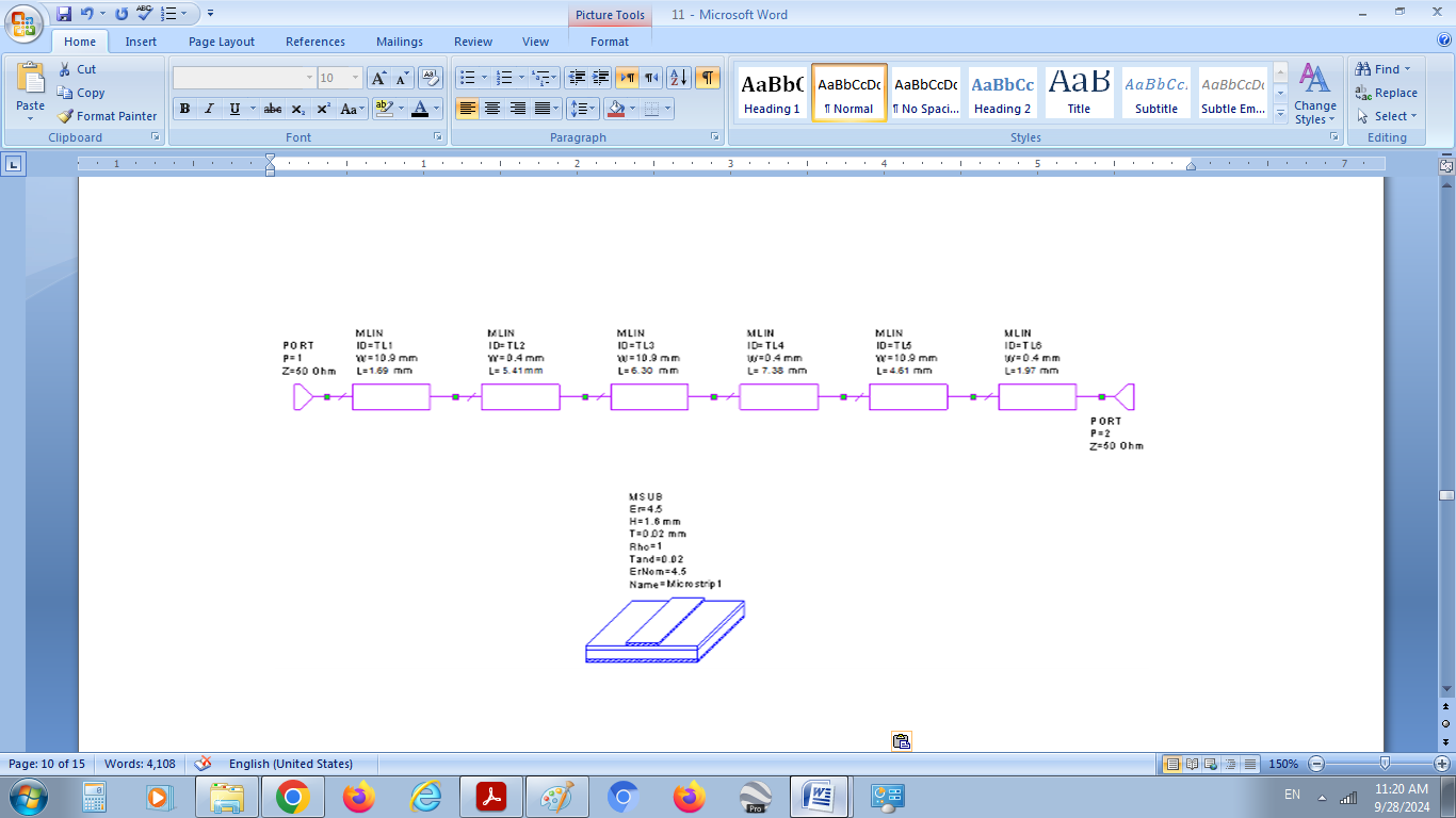 Fig 11: General structure of the stepped-impedance low-pass microstrip filter
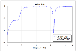
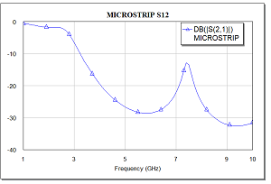
From simulation using Microwave office (V.6.4) can be find out these figures.
|
Fig12: Microstrip filter (Reflection coefficient vs. frequency) |
Fig13: Microstrip filter (Insertion Loss vs. Frequency) |
As it can be seen in figure 13 the low-pass filter indeed similar to the desired low-pass Butterworth filter with approximately 3dB. But to get the desired type, the low-pass filter needs to be tuned adjusting the physical widths and lengths of micro-strip stubs.
F. Design Low-pass Filter Using Lumped Elements:
The equivalent circuit of Low-pass Filter of sixth order is show below, Where: N=6 (is given earlier)

Fig14: The equivalent circuit of Low-pass Filter
Then, from Table 1 above at N= 6 can be obtained the prototype elements values:
C1= 0.5176. C3=1.9318. C5=1.4142.
L2=1.4142. L4= 1.9318. L6=0.5176.
After that, it funded the values of the impedance and frequency transformed elements:
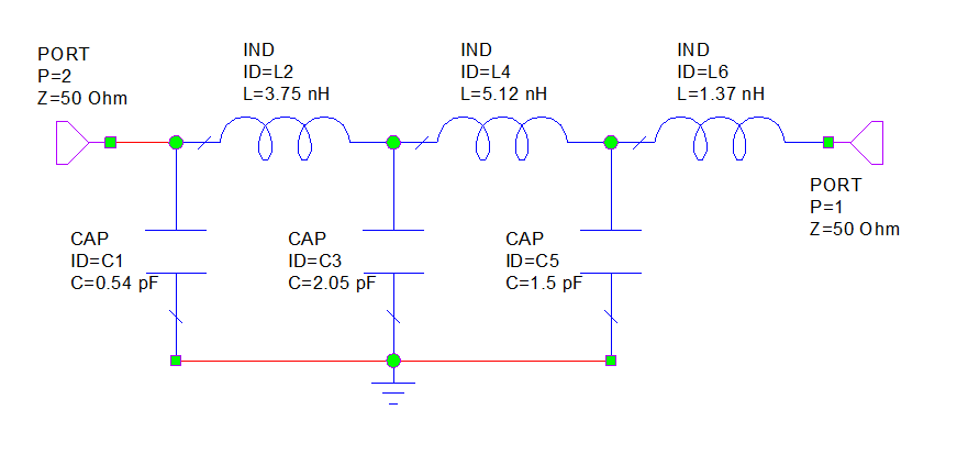
Fig 15: The equivalent circuit of Low-pass Filter
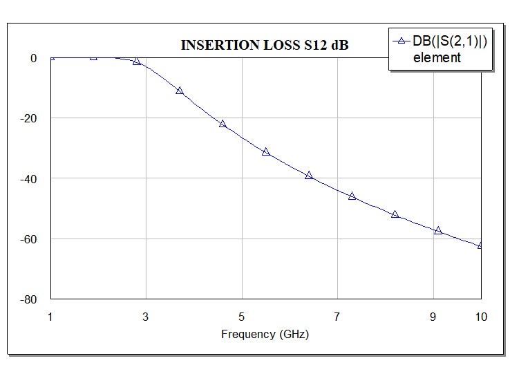
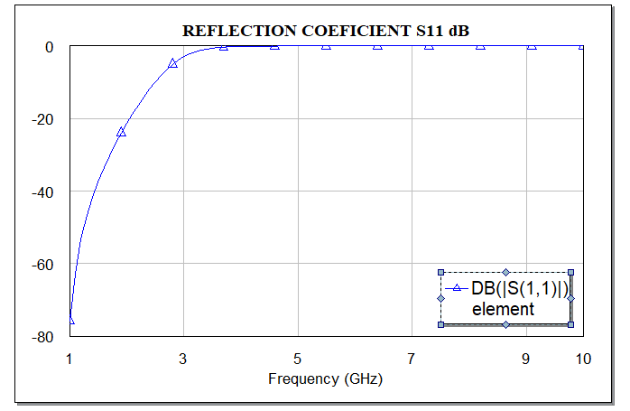
|
Fig 16: the insertion Loss vs. frequency. |
Fig 17:the reflections coefficient vs. frequency |
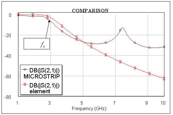
Fig 18: Comparison between lumped element and Microstrip filter at cut frequency 3 GHz
The figure 18 above illustrates the comparison between Low-pass filter using Lumped element and Low-pass filter designed by microstrip. Where, it can be seen Lumped element Low-pass filter is more satisfy than microstrip filter. However, microstrip filter is more stable over temperature conditions because is not using lumped components, where usually until the 100 ohms resistor is printed on the board, and it also has wider bandwidth than lumped type. In addition to that, the microstrip filters have more stringent requirements, higher performance, lighter weight, smaller size, Low fabrication cost and ease of fabrication.
Conclusion
In this study achieved the design of the low-pass filter of order N = 6 with a cut-off frequency 3GHz using microstrip technique and lumped elements. Where, this design can be used for any microwave system dealing with frequencies less than 3GHz, such as Television broadcasting, GSM900, GSM1800 and UMTS of applications of the mobile communications. The use of this design has several benefits: 1) Low pass filters provides as a significant element of any data acquisition system in which be the precision of the obtained data is necessary. 2) Low pass filters reduce the high-frequency noise and interference prior to sampling. 3) Microstrip technology considers better than Lumped element technique in terms of performance, size and cost; therefore, electronic parts can be dispensed.
References
[1] Sarkar, Tapan K., et al. History of wireless. John Wiley & Sons, 2006.? [2] Patil, Vinayak Laxman. Chronological Developments of Wireless Radio Systems before World War II. Springer, 2021.? [3] Chang, Kai. RF and microwave wireless systems. John Wiley & Sons, 2004.? [4] BLANCHARD, Yves; ROHLING, H. The origins and development of Radar: an account of the French contribution. 100 Years of Radar, 2005, 91-120.? [5] Kia Chang, (2000), RF and Microwave Wireless Systems, USA. [6] PIERCE, John R.; KOMPFNER, Rudolf. Transoceanic communication by means of satellites. Proceedings of the IRE, 1959, 47.3: 372-380.? [7] B.Williams and Fred J. Taylor, (2006), Electronic Filter Design Handbook, Forth Edition, USA. [8] AYAZ, Muhammad, et al. “Wireless sensor’s civil applications, prototypes, and future integration possibilities”: A review. IEEE Sensors Journal, 2017, 18.1: 4-30.? [9] ROHDE, Ulrich L.; NEWKIRK, David P. RF/microwave circuit design for wireless applications. John Wiley & Sons, 2004.? [10] DOWLA, Farid. “Handbook of RF and wireless technologies”. Elsevier, 2003.? [11] ULLAH, Md Amanath, et al. “A review on antenna technologies for ambient RF energy harvesting and wireless power transfer: Designs, challenges and applications”. IEEE Access, 2022, 10: 17231-17267.? [12] Edward P. Cunningham, Digital Filtering an Introduction, 1992, USA. [13] D.E Johnson, J.R Johnson and H.P. Moore, 1980, a Handbook of Active Filters, USA. [14] Charles S. Williams, (1986), Designing Digital Filters, USA. [15] Bradford L. Smith and Michel-Henri Carpentier, (1993), the Microwave Engineering Handbook, First Edition, USA. [16] E. da Silva, (2001), High Frequency and Microwave Engineering, UK. [17] R.W. Hamming, (1983), Digital filters, second edition, USA. [18] T. Koryu Ishii, (1995), Handbook of Microwave Technology, UK.
Copyright
Copyright © 2024 Abobkr H. R. Mohamed, Saleman A. A Abobker. This is an open access article distributed under the Creative Commons Attribution License, which permits unrestricted use, distribution, and reproduction in any medium, provided the original work is properly cited.

Download Paper
Paper Id : IJRASET64383
Publish Date : 2024-09-28
ISSN : 2321-9653
Publisher Name : IJRASET
DOI Link : Click Here
 Submit Paper Online

