

Ijraset Journal For Research in Applied Science and Engineering Technology
A Review on the Development of Advanced Fire Safety Robot for Emergency Purposes
Authors: Dosti Jaswanth Kumar Reddy, Cheepurupalli Anantha Satya Chandra sekhar, G. ArunKumar
DOI Link: https://doi.org/10.22214/ijraset.2025.66752
Certificate: View Certificate
Abstract
This paper presents the design and development of an advanced fire safety robot aimed at improving firefighting operations. Detecting and extinguishing fires is challenging and often puts firefighters\' lives at risk. Many firefighters lose their lives each year due to fire accidents while on duty. The robot incorporates Radio Frequency (RF) Operation technology and advanced fire suppression systems to help find and extinguish fires. The location of the fire is detected, and this information is used to control the robot\'s movements—allowing it to move forward, backward, left, and right. An 8051 Microcontroller is used to manage these functions. The design of the robot focuses on agility, durability, and quick deployment, making it suitable for different terrains, including urban areas. Additionally, it has eco-friendly features, such as electric propulsion and sustainable materials, to reduce its environmental impact. The robot is also equipped with a water tank and a pump that can spray water when needed. The main goal of this advanced fire safety robot is to enhance firefighter safety, reduce response times, and minimize damage during emergencies, ultimately helping to save lives and property.
Introduction
I. INTRODUCTION
A robot may be a modified machine that can carry out an assortment of perplexing exercises. Whereas numerous firefighting robots have been created in later a long time, firefighters can control a little number of them electronically [1]. These robots sometimes glitch because of wrong sensor readings, which prevents them from productively putting out fires [2]. In this think about, small depicts an RF (Radio Recurrence) –based fire- fighting robot that can be worked wirelessly conveying superior effectiveness and constancy[3]. Nowadays, robots are more commonly utilized past generation businesses, handling high-risk errands like fire quenching. With this RF-based fire- fighting robot, the chance to human life and property can be essentially decreased, minimizing fire damage[4]. The Fire- Fighting Robot is outlined to function in little spaces, such as within a house, and can quench fires utilizing water. Firefighting could be a physically requesting and perilous errand for firefighters, so this robot offers profitable bolster in unsafe circumstances [5]. Prepared with a water pump associated to an outside water tank through plastic tubing, the robot is designed to handle fire concealment assignments that are also unsafe for people [6]. Robots are perfect for labor-intensive or perilous work and can work in blocked-off situations, diminishing the chance of human life and contributing to lower air pollution [7]. This RF-based Fire- Fighting Robot can move through a demonstrated structure, find a fire, and quench it utilizing water [8]. The paper points of interest the robot's plan, which breaks down the firefighting mission into smaller, proficient assignments. These errands incorporate finding a fire in a particular room, drawing nearer it at a secure separate, and quenching it [9]. One of the key preferences of this robot is its diminished probability of disappointment due to defective sensor readings since an administrator controls it. The RF-based fire-fighting robot effectively checks the whole zone for blazes, identifying and quenching fires sometime recently they spread [10]. This occurs in faster reaction times, avoiding assist damage and ensuring property. A robot is a programmed machine that can carry out a variety of intricate activities [11]. While many firefighting robots have been developed in recent years, firefighters can control a small number of them electronically. These robots occasionally malfunction because of inaccurate sensor readings, which prevents them from efficiently putting out fires [12]. In this study, wee describe an RF (Radio Frequency) –based fire-fighting robot that can be operated wirelessly delivering better efficiency and dependability.
II. PROBLEM STATEMENT
Fire accidents can be unsafe, often putting human lives at risk during rescue and firefighting operations. Firefighters confront challenges such as extraordinarily warm, poisonous smoke, and trouble in getting to fire zones [13]. To move forward with security and proficiency, there's a requirement for a robot that can offer assistance in identifying and battling fires in dangerous ranges. This robot should be able to function remotely, utilizing radio recurrence (RF) innovation, permitting it to be controlled from a secure removal while exploring through smoke, blazes, and impediments [14].
All fires can be quenched by cooling, covering, starving, or hindering the combustion process to quench the fire. One of the foremost common strategies of quenching a fire is by cooling it with water Expanded Security for Firefighters. Inaccessible Operation in Unsafe Zones. Progressed Get to Hard-to-Reach Regions [15].
III. METHODOLOGY
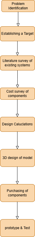
Figure 1: Methodology of development of prototype of fire safety Robot
A. Description of Methodology
To develop a new product, the process begins with problem identification, where the specific issue or need is clearly defined. Next, establishing a target involves setting goals for what the product should achieve, such as performance, safety, and reliability. A literature survey of existing systems helps understand similar products or technologies already in use, ensuring the new design improves on them. The cost survey of components involves researching prices and availability of materials and parts needed for the project to keep it within budget. After that, design calculations are done to ensure the product will perform as intended by considering factors like strength, durability, and functionality. A 3D design of the model is created using CAD software to visualize the product before manufacturing. Once the design is ready, purchasing of components takes place to gather all necessary parts for the prototype. Finally, the prototype is built and tested to check its performance, identify any flaws, and make improvements before launching the final product.
B. Proposed System
The robot will be built from scratch using a plywood framework. Plywood is a good choice because it is strong and stable. The chassis (or base) of the robot should have enough space to hold a water can and all the necessary electronic components. To move, the robot will use four rubber wheels and four DC motors will be fixed at the bottom—one on each side. The water can be placed securely between two plywood frames in the middle of the robot [16]. Sensors will be mounted at the front of the robot to detect flames directly ahead. The circuit will be designed using an RF TX RX module, which will control all the electronic components. All of the electronics, including the RF TX RX, will be securely mounted on the robot. The outlet of the water pump should be fixed at the centre of the robot facing towards the front of the robot [17].
C. Software Development
The robot is implemented using CANVAS software for giving input operations in the microcontroller in C- Language. For communications a modified RF TX RX module is used.
D. Schematic diagram
The 8051-microcontroller advancement board is utilized in this firefighting automated framework, which is made up of HC- ultrasonic sensors. A fire discovery sensor is utilized to recognize smoke or warmth, activating security alarms expeditiously, a temperature sensor is utilized to screen natural warmth, empowering control and computerization frameworks, and an ultrasonic sensor is utilized to degree separate utilizing sound waves, empowering question discovery [14]. In expansion, for quenching the blazes, it also makes utilize of a water tank and a shower weapon instrument with the help of a 12V pump, water is pumped from the water tank to the water spout [18].
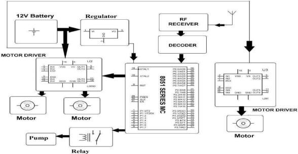
Figure 2: Schematic diagram
IV. COMPONENTS DESCRIPTION & IT’S USES: 4.18051 MICROCONTROLLER
In this project 8051 microcontroller is used as the main controller, in simple 8051 microcontroller is the processor to handle instructions, memory to store information, and input/output ports to connect to other devices like sensors, buttons, or displays.
1851 microcontroller is used to read simple electronics and embedded systems to control small tasks, like turning on lights, controlling motors, or reading data from sensors. Unlike regular computers, which run complex programs, the 8051 is designed to run specific, simple tasks repeatedly and efficiently [19].
Table 1: Specifications of 8051 Microcontroller
|
Board |
Name SKU |
8051 Microcontroller A0000066 |
|
|
Microcontroller USB connector |
ATmega328P USB-B |
|
|
|
Pins |
Built-in LED Pin |
|
13 |
|
|
Digital I/P Pins |
|
14 |
|
Communication |
UART |
|
Yes |
|
|
12C |
|
Yes |
|
Power |
Input Voltage |
|
7-12V |
|
|
DC Current Per I/O Pin Power Supply Connector |
20mA Barrel Plug |
|
|
Memory |
ATmega328P |
|
2KB SRAM,32KB |
|
|
|
|
FlASH,1KB |
|
|
|
|
EEPROM |
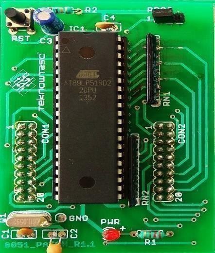
Figure 3: 8051 Microcontroller
A. Fire Detection Sensor
A fire detection sensor is a device that identifies signs of a fire, such as smoke, heat, or flames. It uses these indicators to detect potential fire hazards early, triggering alarms to alert people and sometimes activating safety systems like sprinklers. These sensors are commonly used in homes, offices, and industrial settings to enhance safety by providing early warning and helping prevent fires from spreading.
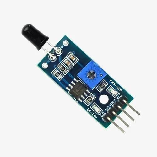
Figure 4: Fire detection Sensor
B. Temperature Sensor
A temperature sensor that measures the heat or coldness of an object or environment. It converts temperature readings into signals that can be read by electronic systems. These sensorsare used in a wide range of applications, from household appliances like thermostats and ovens toindustrial equipment, where they help monitor and control temperatures to ensure safety, efficiency, and proper functioning.
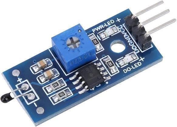
Figure 5: Temperature Sensor
C. Ultrasonic Sensor
An ultrasonic sensor measures the distance between itself and an object using sound waves. It emits high- frequency sound pulses that bounce off the object and return to the sensor. By calculating the time, it takes for the sound to return, the sensor determines the distance to the object. This technology is used in various applications, such as parking assist systems in cars, obstacle detection in robots, and level measurement in tanks.
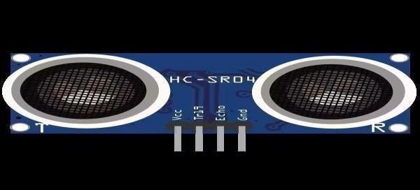
Figure 6: Ultrasonic sensor
D. Battery Description
12 Volts 1.3 Amp Sealed Lead Acid Rechargeable Battery
Maintenance-Free Operation Position-Free and Leakage-Free
Clamps are used to hold components like batteries, motors, and other elements rigidly. Here we had taken a standard available L-clamp in the market of thickness 3mm.
Material=Aluminium (here we have considered weight optimization, as we can also adopt steel material but its mass density is more compared)
V. DESIGN, ANALYSIS AND ACTUAL WORK CARRIED OUT OF THE SAME
A. Water Motor Power
Pump power P(kW) in KW is calculated by multiplying the differential pressure p(Pa) in pascal or N/m2 by 36,000,000 the rate of flow q(m3/hr) in Kilograms per cubic meter, gravity g in m2/s, and the pump differential h(m) meter head[20].
Pump Power (kW)=????(m3/hr) ×????(kg/m3) ×g(m2/s)×h(m)×p(Pa)/3600000 (1)
Let’s assume Q = 2.5 litters/ min = 0.6 m³ /hr Water Density = 997 kg/m³
Spraying Arm length = 0.5 m
Assume Head = 1 m from tank to nozzle.
B. Design, Analysis And Actual Work Carried Out For The Same
Circumferential = ????????^2.............. (2)
G = 9.81 gravity
H = 1m
Assume the Pressure required to supply water from the inlet to the outlet = 2.5 - 3 pascal
Power =0.6∗997∗1∗9.81∗2.53600000=4.0752^-3 Kw
………(3)
Power = 4.0752 watts required to deliver the water from tank to nozzle.
According to availability we will select 4 watts water pump from market
C. Submersible Pump
The standard available motor in the market
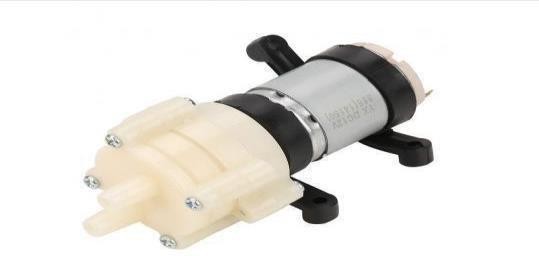
Figure 7: Submersible Pump
VI. ANALYTICAL CALCULATION
A. Design of Support or Frame
1) Area of Rectangular
We took a teak wood frame which is available in the market of thickness 4 mm and length, and width according to requirement.
Thickness = 5mm W = 300 mm
L = 400 mm
The total surface area of the rectangular prism is given by:
A = 2(lb + bh + lh)................. (4)
= 2((400 x 300) + (300 x 5) + (400 x 5))
= 247000 mm2
Mass of frame with Material Ply-wood = 0.385 Kg
= 0.127 x 9.81
= 3.776 N
Area = 247000 mm2
= 0.247m2
Moment of Inertia ICM = 1/12 x M (w2 + l2).......... (5)
= 1/12 x 3.776(400^2 + 300^2)
= 78666.6 Nmm2
Figure 8: Plywood from SolidWorks
Assume load on the frame including all components = 5Kg
Mass of water storage = 2.5-3 litters
=3kg Total mass on frame = 5+3
= 8Kg
= 8*9.81
= 78.48 N
Factor of Safety = 1.5
= 78.48 X 1.5
= 117.72 N
= 120 N
Perpendicular distance = 400 / 2
= 200 mm
Moment = 120 X 200
= 24000 Nmm2
= 24000 Nmm2
I = 78666.6 Nmm2
Y = Distance of the layer at which the bending stress is considered
=5/2
= 2.5 mm
Sigma b = M * Y / (I)................. (6)
= 24000 * 2.5 / (78666.6)
= 0.762 Mpa
0.127 MPa <Plywood 13.8 MPa Ultimate Yield strength Hence Design is safe.
2) Motor Selection On The Total Payload Of Component
Hence total weight on the frame is taken in frame calculation = 120 N
No Motors required= 4 at back side wheels Load is distributed into 4 wheels = 120/4 = 30N
Actual load = total load / no. of Motors
= 120/4
= 30N
The diameter of the inside hole of a wheel is 8mm Torque = ½ Force x Diameter
=1/2x30 x8 mm
=120 N.mm
=0.12 Nm.
=1.22365 Kg-cm torque
Note
Diameter =diameter of the wheel (d= 80mm) standard available in the market, internal diameter (d 10mm).
Force =total force including all components (30N) at each wheel
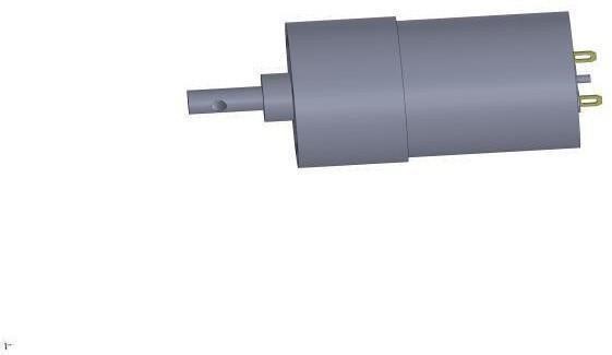
Figure 9: Motor from SolidWorks
3) Specifications of Motor
Rate base motor RPM = 18000 rpm Rate Speed (RPM) = 200 rpm Operating Voltage(VDC) = 6W18V Voltage = 12V
Rated Torque = 3.9 kg-Cm
Load current max = 900 MA
Motor Diameter = 2.7 mm
Motor Length = 62 mm
4) Clamp for holding motor rigidity
Clamps are used to securely hold components like batteries, motors, and other parts in place. In this case, we selected a standard L-clamp available in the market with a thickness of 3mm. The material chosen is aluminium because it offers weight optimization. Although steel could also be used, aluminium was preferred due to its lower mass density, making it lighter.
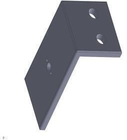
Figure 10: Clamp From SolidWorks
5) Discussion
The selection of appropriate frame material and its dimensions is crucial to ensure the structural stability and durability of the fire-fighting robot. A sturdy frame is essential to support all components, including the clamps for holding motors, which are selected based on strength and compatibility with the frame material. The wheels are chosen to provide optimal mobility on various terrains, ensuring the robot can navigate smoothly during operations. The DC motors, selected for their efficiency and torque, drive the wheels and water pump, ensuring reliable performance. The water pump is selected to provide sufficient pressure for extinguishing fires effectively.
After conducting a detailed market survey and considering the required specifications, standard components were chosen to meet the design criteria. Therefore, the overall design and preparation of the fire-fighting robot have been completed as per the established standards to ensure functionality, reliability, and safety in firefighting applications.
VII. PROPOSED GEOMETRIC MODEL OF FIRE SAFETY ROBOT
Design has been done using Solid Works. First all the sub-parts are Designed using part design module.
Then all the sub-parts are assembled using the product module in the solid works.
Finally assembled part has been done using Solid Works and saved as a PDF.
References
[1] Aftab Nagarji, Aniket Vani, Pratik Kumathe, Prof. N.S. Nadaf - Fire Fighting Robotic Vehicle Using Arduino. International Research Journal of Modernization in Engineering Technology and Science, Volume: 04, 2022. [2] Brian J. Meacham - Fire Performance and Regulatory Considerations with Modern Methods of Construction. Buildings and Cities, 3(1), pp. 464–487, 2022. [3] Chirag Praful Mahant, Limchand Rajesh Koshariya, Ganesh Bhakre, Chakradhar Bhimrao Khandekar, Kartik Sanjay Munje, Harsh S. Badge, Akshay Kumar Waghmare - Radio Frequency Controlled Fire Fighting Robot: A Review. International Journal of Innovative Engineering and Science (IJIES), Vol. 7, No. 3, pp. 05-08, 2022. [4] Ch. Naresh, Rashmitha, Soumya, Sathvika Veeramreddy - RF Controlled Fire Fighting Robot with High Pressure Water Sprinkler. Journal of Engineering Sciences, Vol. 13, 0377- 9254, 2022. [5] Chu Zhang, Won-Hwa Hong, Young-Hoon Bae- Fire Safety Knowledge of Firefighting Equipment Among Local and Foreign University Students. International Journal of Environmental Research and Public Health, 19, 12239, 2022. [6] Eduardo González-Gironda, Juan Jesús Roldán- Gómez, Antonio Barrientos - A Survey on Robotic Technologies for Forest Firefighting: Applying Drone Swarms to Improve Firefighters’ Efficiency and Safety. Applied Sciences, 11, 363, 2021. [7] Jonathan,L. Hodges, Urvin Salvi, Anil Kapahi - Design Fire Scenarios for Engine Passenger Vehicles. Fire Safety Journal, Volume 146, 104145, 2024. [8] Jonna Hynynen, Maria Quant, Roshni Pramanik, Anna Olofsson, Ying Zhen Li, Magnus Arvidson, Petra Andersson - Safety and Transport Fire Safe Transport. RISE, 42, 2022. [9] Mrunalini B. Morwal, Karishma K. Malewar, Shubham R. Gadpal, Nilesh S. Panchbudhe - Design & Implementation of RF Based Fire Fighting Robot. Journal of Emerging Technologies and Innovative Research (JETIR), Volume: 06, Issue: 02, 2019. [10] Myriam Martínez-Fiestas, Ignacio Rodríguez- Garzón, Antonio Delgado-Padial - Firefighter Perception of Risk: A Multinational Analysis. Safety Science, 123, 104545, 2020. [11] Martin Lyubomirov Ivanov, Wan-Ki Chow - Autonomous searching, detecting, and extinguishing burnt areas. Extinguish fire them in rural areas using a wireless connection The robot can be moved in any direction required using 8051 Micro Controller and RF Technology. Fire Safety in Modern Indoor and Built Environment. Indoor and Built Environment, Vol. 32(1), pp. 3–8, 2022. [12] Naijie Chai, Wenliang Zhou, Ziyu Chen, Gabriel Lodewijks, Yingying Zhao - Multi- Attribute Fire Safety Evaluation of Subway Stations Based on FANP – FGRA – Cloud Model. Tunnelling and Underground Space Technology, Volume 144, 105526, 2024. [13] Numan Khan, Kamarah Pooley - The Effect of Firefighter-Delivered Fire Safety Education on Young People Who Misuse Fire. Fire Safety Journal, 115, 103156, 2020. [14] Shaikh Z. A. R., M, Pintu Kumar Mahato, Chitranjan Kumar, Aniruddh Ghayale, Mujjfar Shaikh - Fire Fighting Robotic Vehicles. International Journal of Innovative Engineering Research and Technology (IJIERT),Volume 11, Issue 02, 2024. [15] Salvatore Digiesia, Nicola Laurieri, Andrea Lucchese, Giovanni Piccininno - T-Fire System: A Novel Integrated Fire Monitoring and Extinguishing System for Trucks. Procedia Computer Science, 232, 2468–2477, 2024. [16] Sara Waring, Susan Giles, Pippa Carlton, Verity Buchanan - Examining the Cost-Effectiveness of Fire Service Prevention and Youth Engagement Activities. Fire Safety Journal, 147, 104186, 2024. [17] Trevor Hocksun Kwan, Zhuohang Zhang, Jiale Huang, Qinghe Yao - Fire Safety Parametric Analysis of Vehicle-Mounted Hydrogen Tanks Based on a Coupled Heat Transfer and Thermomechanics Model. International Journal of Hydrogen Energy, Volume 50, Part , Pages 792-803, 2024. [18] Wan-Ching Li, Jo-Ming Tseng, Hsin-Shu Huang - Effectiveness of Advanced Fire Prevention and Emergency Response Training at Nursing Homes. International Journal of Environmental Research and Public Health, 19, 13185, 2022. [19] Xiaoning Zhang, Yishuo Jiang, Xiqiang Wu, Zhuojun Nan, Yaqiang Jiang, Jihao Shi, Yuxin Zhang, Xinyan Huang, George G.Q. Huang - AIoT-Enabled Digital Twin System for Smart Tunnel Fire Safety Management. Developments in the Built Environment, Volume 18, 100381, 2024. [20] Yong-taek Han - Study on the Development of Multi-Purpose Fire Engines Through Vehicle Safety Factor Design. International Journal of Fire Science and Engineering, Vol. 36, No. 3, pp. 18-28, 2022.
Copyright
Copyright © 2025 Dosti Jaswanth Kumar Reddy, Cheepurupalli Anantha Satya Chandra sekhar, G. ArunKumar. This is an open access article distributed under the Creative Commons Attribution License, which permits unrestricted use, distribution, and reproduction in any medium, provided the original work is properly cited.

Download Paper
Paper Id : IJRASET66752
Publish Date : 2025-01-30
ISSN : 2321-9653
Publisher Name : IJRASET
DOI Link : Click Here
 Submit Paper Online