Ijraset Journal For Research in Applied Science and Engineering Technology
- Home / Ijraset
- On This Page
- Abstract
- Introduction
- Conclusion
- References
- Copyright
Study and Analysis of Diagrid Structures with Conventional Frame Structure
Authors: Harshit Mahajan, Mahroof Ahmed
DOI Link: https://doi.org/10.22214/ijraset.2024.63925
Certificate: View Certificate
Abstract
The structure is the backbone of building Construction of the multi?storey building is quickly increasing throughout the globe. Advances in construction technology, materials, structural systems, analysis and design software package expedited the expansion of those buildings. Diagrid buildings square measure rising as structurally economical furthermore as architecturally important assemblies for tall buildings. The diagrid structural system may be outlined as a diagonal member shaped as a framework created by the intersection of various materials like metals, concrete or wood beams that are used in the construction of buildings and roofs. Diagrid structures of the steel members are efficient in providing a solution both in term of strength and stiffness. In this study the safety and minimum harm level of a structure may well be the prime demand of high-rise buildings. In this thesis Analysis and design of 16 storey diagrid building with plan of 18 m × 18 m size is considered.
Introduction
I. INTRODUCTION
Construction of the multi?storey building is quickly increasing throughout the globe. Advances in construction technology, materials, structural systems, analysis and design software package expedited the expansion of those buildings. Diagrid buildings square measure rising as structurally economical furthermore as architecturally important assemblies for tall buildings. Recently the diagrid structural system has been wide used for tall buildings due to the structural efficiency and aesthetic potential provided by the distinctive geometric configuration of the system. Generally, for tall building diagrid structure steel is employed. In present work, concrete diagrid structure with completely different shapes is analysed and compared with a conventional concrete building. The structural design of high-rise buildings is ruled by lateral loads because of wind or earthquake. Lateral load resistance of the structure is provided by the inside structural system or exterior structural system. because of inclined columns, lateral loads are resisted by axial action of the diagonal in diagrid structure compared to bending of vertical columns within the typical building. The diagrid structural system may be outlined as a diagonal member shaped as a framework created by the intersection of various materials like metals, concrete or wood beams that are used in the construction of buildings and roofs. Diagrid structures of the steel members are efficient in providing a solution both in term of strength and stiffness. But these days a widespread application of diagrid is employed within the giant span and high-rise buildings, significantly after they area unit complicated geometries and arced shapes. Diagrid structure consists of inclined columns on the exterior surface of the building. Due to inclined columns, lateral loads are resisted by axial action of the diagonal compared to bending of vertical columns in framed tube structure. Diagrid structures typically, don't need core because of lateral shear may be carried by the diagonals on the outer boundary of a building.
II. OBJECTIVE OF STUDY
For comparison of this buildings under the same seismic zone, the parameter in both type of the buildings is taken same.
- The work is to be carried out by conducting?
- Modelling of both the building frames.
- Analysis of building frames considering seismic parameters.
- Study of results in terms of moments, stresses & Moment in Slab, forces, drift, deflection, and the economy
III. MODELLING
A. Modelling and Analysis
Different Model of building considered is given below:
Model-1 Conventional Building Denoted as CB
Model-2: Square Diagrid Building denoted as SDB
Model-3: Circular Diagrid Building denoted as CDB
Model-4: Triangular Diagrid Building denoted as TDB???????
B. Preliminary Sections and materials considered:
The plan area for the proposed work is 18 x 18 m in which size of panels is 3x3 m for conventional and square diagrid building and similar area consider for circular and triangular buildings the preliminary sections of columns and beams were fixed based on deflection criteria [i.e. span to depth ratio]. The sections were found to be satisfactory for the given loads for a 16 storied model. These sections were maintained uniform throughout the height. Similarly, all other models of were analysed and meet the current Codes (IS 456:2000 and IS 1893:2002) and their structural member sizes chosen for the study are given in table below
???????C. Design Parameters- Here the Analysis is being done for G+16 building by computer software using STAAD-Pro.
Table 1 Design parameters
|
S.No |
Particulars |
Dimension/Size/Value |
|
1 |
Model |
G+16 |
|
2 |
Seismic Zones |
IIIrd |
|
3 |
Floor height |
3.6 |
|
4 |
The configuration of both the models |
Square, Circular and triangular |
|
5 |
Angle of diagrid- |
67.4° |
|
6 |
Plan size |
18X18 |
|
7 |
Size of columns |
500mmX500mm |
|
8 |
Size of beams |
300mmX500mm |
|
9 |
Thickness of slab |
120mm |
|
10 |
Size of Diagonals |
300X500 |
|
11 |
Type of soil |
Medium soil Type-II |
|
12 |
Dead Load |
10 & 12 KN/N2 (Roof & Floor) |
|
13 |
Live load |
3 &1.5KN/M2 (Roof & Floor) |
|
14 |
Material used |
Grade of Concrete M25& Steel Fe415 |
|
15 |
Dynamic Analysis |
Response Spectrum Analysis& Wind analysis |
|
16 |
Fundamental natural period of building |
Ta = 0.075 h0.75 |
|
17 |
Zone factor Z |
0.16 |
|
18 |
Response Reduction factor (RF) |
5 |
|
19 |
Importance factor (I) |
1 |
|
20 |
Rock and soil factor (SS) |
2 |
|
21 |
Type of structures |
1 |
|
22 |
Damping ratio (DM) |
0.05 |
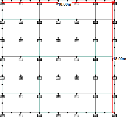
Plan area of Conventional and Square diagrid Building= 18*18
= 324 sq. meter
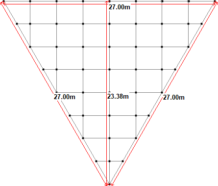
Plan area of Triangular building
= 316 sq. Meter approx.
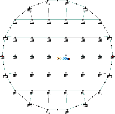
Plan area of Circular Building
= 315 sq. Meter approx.
Figure 1 Plan area of Different Shapes of Diagrid buildings
IV. RESULT AND DISCUSSION
A. Peak Storey Shear
Table 2 Peakstorey Shear for Seismic Analysis
|
PEAK STORY SHEAR IN KN |
STORY |
CB |
SDB |
CDB |
TDB |
|
16 |
206 |
194 |
227 |
132 |
|
|
15 |
450 |
410 |
478 |
295 |
|
|
14 |
667 |
590 |
867 |
419 |
|
|
13 |
852 |
731 |
1030 |
522 |
|
|
12 |
1001 |
842 |
1258 |
595 |
|
|
11 |
1117 |
919 |
1346 |
650 |
|
|
10 |
1204 |
982 |
1467 |
690 |
|
|
9 |
1273 |
1028 |
1520 |
725 |
|
|
8 |
1334 |
1077 |
1613 |
758 |
|
|
7 |
1399 |
1125 |
1666 |
798 |
|
|
6 |
1474 |
1184 |
1785 |
842 |
|
|
5 |
1559 |
1250 |
1862 |
897 |
|
|
4 |
1651 |
1326 |
2030 |
955 |
|
|
3 |
1738 |
1411 |
2132 |
1020 |
|
|
2 |
1812 |
1498 |
2232 |
1080 |
|
|
1 |
1883 |
1582 |
2325 |
1134 |
|
|
0 |
2030 |
1647 |
2396 |
1172 |
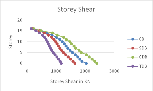
Graph 1 Storey vs peak storey shear
Peak storey shear decreases 16 % average at each story in Square diagrid building when is compare to conventional building with similar plan area.
Peak storey shear increases 20% average at each story in Circular diagrid building when is compare to conventional building with similar plan area.
Peak storey shear decreases 40% average at each story in Triangular diagrid building when is compare to conventional building with similar plan area
B. Node Displacement for Seismic force
Table 3 Node displacement for seismic Analysis
|
NODE DISPLACMENT IN X DIRECTION (mm) |
STORY |
CB |
SDB |
CDB |
TDB |
|
16 |
43.894 |
15.825 |
22.034 |
17.052 |
|
|
15 |
42.849 |
15.089 |
20.956 |
16.295 |
|
|
14 |
41.509 |
14.278 |
19.828 |
15.214 |
|
|
13 |
39.867 |
13.445 |
18.625 |
14.319 |
|
|
12 |
37.958 |
12.565 |
17.391 |
13.223 |
|
|
11 |
35.818 |
11.664 |
16.106 |
12.238 |
|
|
10 |
33.481 |
10.762 |
14.827 |
11.146 |
|
|
9 |
30.971 |
9.835 |
13.509 |
10.114 |
|
|
8 |
28.303 |
8.934 |
12.235 |
9.06 |
|
|
7 |
25.488 |
8.005 |
10.924 |
8.026 |
|
|
6 |
22.526 |
7.126 |
9.693 |
7.03 |
|
|
5 |
19.413 |
6.211 |
8.414 |
6.025 |
|
|
4 |
16.16 |
5.369 |
7.248 |
5.108 |
|
|
3 |
12.783 |
4.469 |
6.028 |
4.172 |
|
|
2 |
9.309 |
3.692 |
4.973 |
3.342 |
|
|
1 |
5.788 |
2.854 |
3.792 |
2.447 |
|
|
0 |
2.362 |
2.102 |
2.529 |
1.773 |
C. Node Displacement for Wind effect
Table 4 Node Displacement for Wind forces
|
NODE DISPLACMENT IN X DIRECTION (mm) |
STORY |
CB |
SDB |
CDB |
TDB |
|
16 |
12.491 |
14.993 |
21.804 |
13.83 |
|
|
15 |
12.422 |
14.972 |
22.075 |
24.287 |
|
|
14 |
12.261 |
14.764 |
21.481 |
12.819 |
|
|
13 |
12.013 |
14.52 |
21.436 |
23.555 |
|
|
12 |
11.675 |
14.108 |
20.524 |
11.603 |
|
|
11 |
11.251 |
13.65 |
20.161 |
22.564 |
|
|
10 |
10.74 |
13.032 |
18.934 |
10.252 |
|
|
9 |
10.145 |
12.368 |
18.257 |
21.316 |
|
|
8 |
9.466 |
11.54 |
16.718 |
8.749 |
|
|
7 |
8.705 |
10.658 |
15.73 |
19.786 |
|
|
6 |
7.865 |
8.535 |
13.888 |
7.104 |
|
|
5 |
6.947 |
7.308 |
12.595 |
17.921 |
|
|
4 |
5.954 |
5.996 |
10.461 |
5.289 |
|
|
3 |
4.89 |
4.61 |
8.871 |
15.619 |
|
|
2 |
3.758 |
3.082 |
6.461 |
3.396 |
|
|
1 |
2.563 |
1.53 |
4.646 |
2.418 |
|
|
0 |
1.308 |
1 |
2.054 |
1.122 |
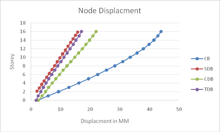
Graph 2 Storey vs Displacement for Seismic Analysis
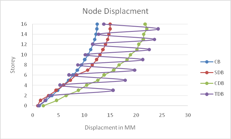
Graph 3 Storey Vs displacement for Wind Analysis
1) Node Displacement for Seismic Forces
Node displacement decreases 62 % average at each story in Square diagrid building when is compare to conventional building with similar plan area.
Node displacement decreases 40% average at each story in Circular diagrid building when is compare to conventional building with similar plan area.
Node displacement decreases 62% average at each story in Triangular diagrid building when is compare to conventional building with similar plan area.
2) Node Displacement for Wind Forces
Node displacement increases 20 % average at each story in Square diagrid building when is compare to conventional building with similar plan area.
Node displacement increases 70% average at each story in Circular diagrid building when is compare to conventional building with similar plan area.
Uneven increment seen at each story in Triangular diagrid building when is compare to conventional building with similar plan area.
D. Story Drift
|
STORY DRIFT IN X DIRECTON(MM) |
STORY |
CB |
SDB |
CDB |
TDB |
|
16 |
0.0003 |
0.0002 |
0.0003 |
0.0002 |
|
|
15 |
0.0004 |
0.0002 |
0.0003 |
0.0003 |
|
|
14 |
0.0005 |
0.0002 |
0.0003 |
0.0002 |
|
|
13 |
0.0005 |
0.0002 |
0.0003 |
0.0003 |
|
|
12 |
0.0006 |
0.0003 |
0.0004 |
0.0003 |
|
|
11 |
0.0006 |
0.0003 |
0.0004 |
0.0003 |
|
|
10 |
0.0007 |
0.0003 |
0.0004 |
0.0003 |
|
|
9 |
0.0007 |
0.0003 |
0.0004 |
0.0003 |
|
|
8 |
0.0008 |
0.0003 |
0.0004 |
0.0003 |
|
|
7 |
0.0008 |
0.0002 |
0.0003 |
0.0003 |
|
|
6 |
0.0009 |
0.0003 |
0.0004 |
0.0003 |
|
|
5 |
0.0009 |
0.0002 |
0.0003 |
0.0003 |
|
|
4 |
0.0009 |
0.0003 |
0.0003 |
0.0003 |
|
|
3 |
0.0010 |
0.0002 |
0.0003 |
0.0002 |
|
|
2 |
0.0010 |
0.0002 |
0.0003 |
0.0002 |
|
|
1 |
0.0010 |
0.0002 |
0.0004 |
0.0002 |
|
|
0 |
0.0007 |
0.0006 |
0.0007 |
0.0005 |
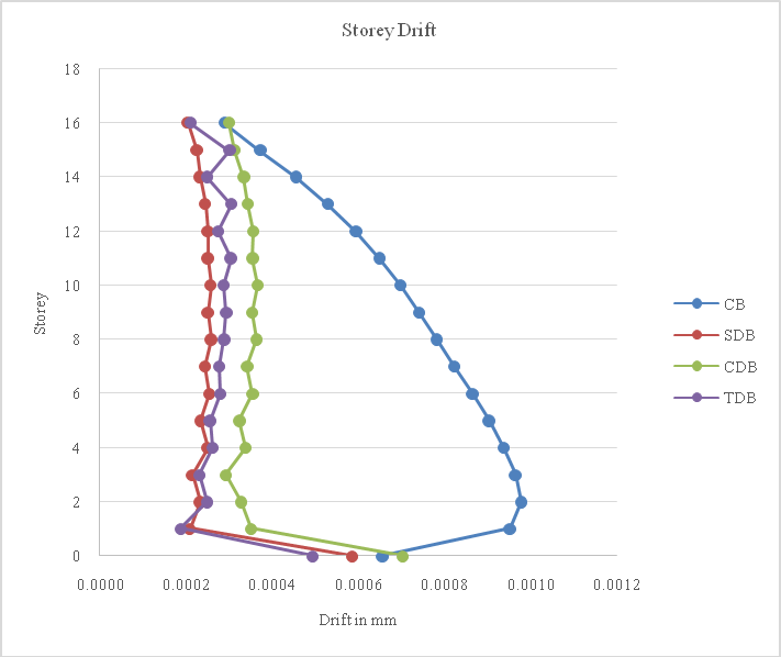 ???????
Graph 4 Storey Drift for Seismic Analysis
Conclusion
Response spectrum analysis results provides a more realistic behaviour of structure response and diagrid structure is more effective in lateral load resistance Seismic and wind analysis of conventional building with different shapes of diagrid building with equivalent plan area at seismic zone III is carried out and the following conclusions are drawn from the study: 1) Total base shear increasesin circular shape of diagrid building and decreases in square and triangular shape of diagrid building when compare with conventional building for seismic analysis. 2) It concludes that the node displacement is decreases in all shapes of diagrid buildings when compare with conational type of building. 3) The values of storey drift are found to be within permissible limit i.e. not more than 0.004 times the storey height as per norms according to IS 1893:2002 (Part-1) for both analysis seismic and wind. 4) Its concluded Diagrid building shows less lateral displacement and drift in comparison to conventional building.
References
[1] IrfanSaleem, Dr. Sunil Kumar Tengli-Parametric Study on Asymmetric Diagrid Structures- International Journal of Applied Engineering Research ISSN 0973-4562 Volume 13, Number 7 (2018) pp. 61-66 [2] Akshat -A Review Paper on Seismic Pareformance of High-Rise Building using Bracing, Diagrid and Outrigger System- July 2020 International Journal of Engineering Research and V9(06) [3] TruptiAmitKinjawadekar , Amitkinjawadekar- Comparative study of seismic characteristics of diagrid structural systems in high rise construction-June 2018 International Journal of Civil Engineering and Technology 9(6):315-323 [4] ChetanS.Pattar- Analysis of Diagrid structures and Bare frame structures using E-TABS with Comparing both Symmetric and Asymmetric Plan - © 2020 JETIR July 2020, Volume 7, Issue 7 [5] Ravi Sorathiya- study on diagrid structure of multistorey building- International Journal of Advance Engineering and Research Development - Volume 4, Issue 4, April -2017 Volume 4, Issue 4, April -2017 [6] Avnish Kumar Rai- comparative analysis of a high rise building frame with and without diagrid effects under seismic zones iii & v- Ijesrt International Journal of Engineering Sciences & Research Technology-2019 [7] shubhangi v. pawar- a comparative study on diagrid over conventional structures using steel and concrete diagrids- © 2020 jetiroctober 2020, volume 7, issue 10 [8] snehal s. mali- review paper on diagrid system in tall buiding- international research journal of engineering and technology (irjet)- volume: 06 issue: 08 | aug 2019 [9] [9] Deep Bajoria- Analysis of Multi-Storey Building with and without Diagrid System Using ETABS- © May 2019 | IJIRT | Volume 5 Issue 12 | ISSN: 2349-6002 [10] [10] Ravish Khan , S.B. Shinde- analysis of diagrid structure in comparison with exterior braced frame structure- International Journal of Research in Engineering and Technology- eISSN: 2319- 1163 | pISSN: 2321-7308 [11] Kamath, K- An Analytical Study on Performance of a Diagrid Structure Using Nonlinear static Pushover Analysis- [12] Manthan I. Shah- Comparative Study of Diagrid Structures with Conventional Frame Structures- International Journal of Engineering Research and Applications 6(5):22-29
Copyright
Copyright © 2024 Harshit Mahajan, Mahroof Ahmed. This is an open access article distributed under the Creative Commons Attribution License, which permits unrestricted use, distribution, and reproduction in any medium, provided the original work is properly cited.

Download Paper
Paper Id : IJRASET63925
Publish Date : 2024-08-09
ISSN : 2321-9653
Publisher Name : IJRASET
DOI Link : Click Here
 Submit Paper Online

