Ijraset Journal For Research in Applied Science and Engineering Technology
- Home / Ijraset
- On This Page
- Abstract
- Introduction
- Conclusion
- References
- Copyright
Dynamic Analysis of Underground Water Tank Considering Fluid - Structure Interaction
Authors: Shweta Rajoriya, Dr. Raghvendra Singh
DOI Link: https://doi.org/10.22214/ijraset.2024.65619
Certificate: View Certificate
Abstract
In this research paper the main focus on dynamic analysis of open rectangular underground water tanks, focusing on the interaction between the fluid stored within and the structural integrity of the tank. In this paper Understanding the dynamic behavior of these tanks under with different loading scenarios like bending moments, loads, and displacement in water tank essential for ensuring their stability and safety. This project employs numerical technique to simulate and analyze the fluid-structure interaction (FSI) by using staad pro connect in which we use finite element method in underground water tanks. In this research we analyze the open rectangular underground water tank of capacity 576000 liter of water tank by using IS code 456 -2000 code for plain and reinforced concrete.
Introduction
I. INTRODUCTION
A. Fluid-structure-interaction (FSI)
The interrelate between fluid, structure, and soil significantly influences the dynamic behavior of fluid-containing structures. Fluid-structure interaction (FSI) arises at the interface between the fluid and the structure, where hydrodynamic pressure exerts forces on the structure, and structural movements, in turn, generate effective fluid loads. This interaction can be studied using various techniques, including added mass methods, finite element methods (FEM) with Lagrangian, Eulerian, or combined Lagrangian-Eulerian approaches, and analytical models like Housner's two-mass representation or Bauer's multi-mass representations.
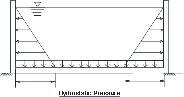
Load combination on water tank:
1) Empty Tank
When the tank is empty, external loads from saturated soil exert significant pressure on the tank walls (Figure 2a). This condition represents a critical loading scenario for design, as the tank must resist external forces without internal support from water.
2) Full Tank
When the tank is full, hydrostatic pressure from the water inside the tank dominates, while the surrounding soil may shrink away from the walls (Figure 2b). In this scenario, the walls are subjected to internal pressure without counteracting external soil pressure.
- Normal Condition Of Water Tank: - Dead Load + Live Load + Earth Pressure;
- Full Condition Of Water Tank: - Dead Load + Live Load + Earth Pressure.
- Empty Condition Of Water Tank: - Dead Load + Live Load + Earth Pressure + Water Pressure.

Fig :- 2(a) Fig :- 2(b)
Sketches Shows When Tank Is Empty Sketches Shows When Tank Is Full
II. LITERATURE REVIEW
- Issar kapadia. Had done the “design, analysis and comparison of underground rectangular water tank by using staad provi8 software”. This paper includes the study of UG Rectangular tank that how the shape deflected and what are the actions will be produced when tank empty or full by using STAAD Pro software is discussed.
- Housner, G. W. (1963). The dynamic behavior of water tanks. Bulletin of the Seismological Society of America, 53(2), 381-387.
- Akiyama, H., & Yoshimura, S. (2002). Seismic response analysis of underground water tanks considering soil-structure interaction. Engineering Structures, 24(9), 1203-1211.
- Gogoi, I., & Maity, D. (2007). Seismic analysis of elevated water tanks with fluid-structure interaction. Journal of Sound and Vibration, 326(3-5), 370- 385.
- Nallanathel. M et al. showed that corner stresses and maximum shear and bending stresses are less in case of circular tanks than remaining other designs and the shapes of water tanks plays vital role in the stress distribution and overall economy and by using Staad pro, the results obtained was very accurate than conventional results.
- B.V. Ramana Murthy, M Chiranjeevi had done the “design of rectangular water tank by using staad pro software.”
III. METHODOLOGY
A. Added mass method
1) Introduction
The added mass method is a mathematical approach utilized to quantify the additional mass exerted on a structure due to its interaction with a surrounding fluid. This phenomenon, termed added mass, occurs when a structure either moves through a fluid or remains stationary while the fluid moves around it. The interaction generates an inertial effect caused by the displacement of the fluid, influencing the structure's dynamics.
2) Principle
The added mass method operates on the principle of conservation of momentum, where the fluid's momentum, influenced by the structure’s motion, creates an equivalent additional mass effect on the structure. This induced mass is integrated into the dynamic motion equations, enabling accurate representation of the structural behavior under fluid-induced loads.
3) Mathematical Formulation
In the added mass method, the added mass is typically expressed as a function of the fluid density, the geometry of the structure, and the relative velocity between the fluid and the structure. The added mass matrix, often denoted as M????, represents the mass-like effects induced by the fluid and is added to the mass matrix of the structure in the dynamic equations.There is a formula used to calculate the added mass for a structure interacting with a fluid. The added mass matrix M???? is typically defined as:
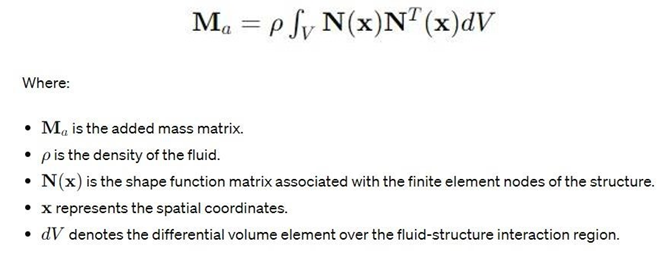
This integral equation represents the contribution of the fluid to the added mass experienced by the structure. The shape functions N(????) describe the displacement of the structure at each finite element node, and the integration is performed over the volume of the fluid-structure interaction domain.
The added mass matrix M is then incorporated into the dynamic equations of motion for the structure to account for the additional mass induced by the fluid. This allows for a more accurate prediction of the dynamic response of the structure under fluid loading conditions.
B. Implementation
Implementation of the added mass method typically employs Numerical Techniques such as finite element analysis (FEA)
The process involves:
- Problem Formulation: Establishing fluid-structure interaction parameters and boundary conditions.
- Iterative Solution: Solving the coupled system of equations iteratively to capture the structural response.
- Dynamic Analysis: Incorporating added mass effects into the motion equations for accurate simulation of fluid-induced loads.
IV. MODELLING AND ANALYSIS
A. Finite Element Method
1) Introduction
The Finite Element Method (FEM) is a highly effective numerical technique used for analyzing and modeling complex systems in engineering. It is extensively applied across a variety of fields, such as structural engineering, mechanical engineering, and civil engineering, to solve problems related to stress analysis, heat transfer, fluid flow, and electromagnetic fields.
MODELING AND ANALYSIS:
At first analyze the open rectangular shape underground water tank of capacity 576000 litre. The dimension of underground tank is 12m*8m*6m and thickness is 0.25mm.Using code IS 456 In compressive strength of concrete is 30 KN/m square and yield stress 415KN/m square . Analysis is being done by the help of stadd pro v8i software. After provide All required Structural configuration we will assign stresses and load calculation in it.
Table :1 Structural configuration
|
S.no. |
Parameter |
Size |
|
1. |
Capacity of water tank |
576m3 |
|
2. |
Shape of water tank |
Rectangular |
|
3. |
Unit weight of soil |
40 KN/m2 |
|
4. |
Angle of internal friction (?) |
37º |
|
5. |
Bearing capacity of soil |
230 KN/m2 |
|
6. |
Thickness of plate |
0.25m |
|
7. |
Size of tank |
12x8x6m |
|
8. |
Grade of concrete |
M25 |
|
9. |
Yield strength |
Fe415 |
|
10. |
Hydrostatic pressure |
30 KN/m2 |

PLAN AND ELEVATION OF WATER TANK
- Modeling by Staad.Pro connect Finite Creating Model
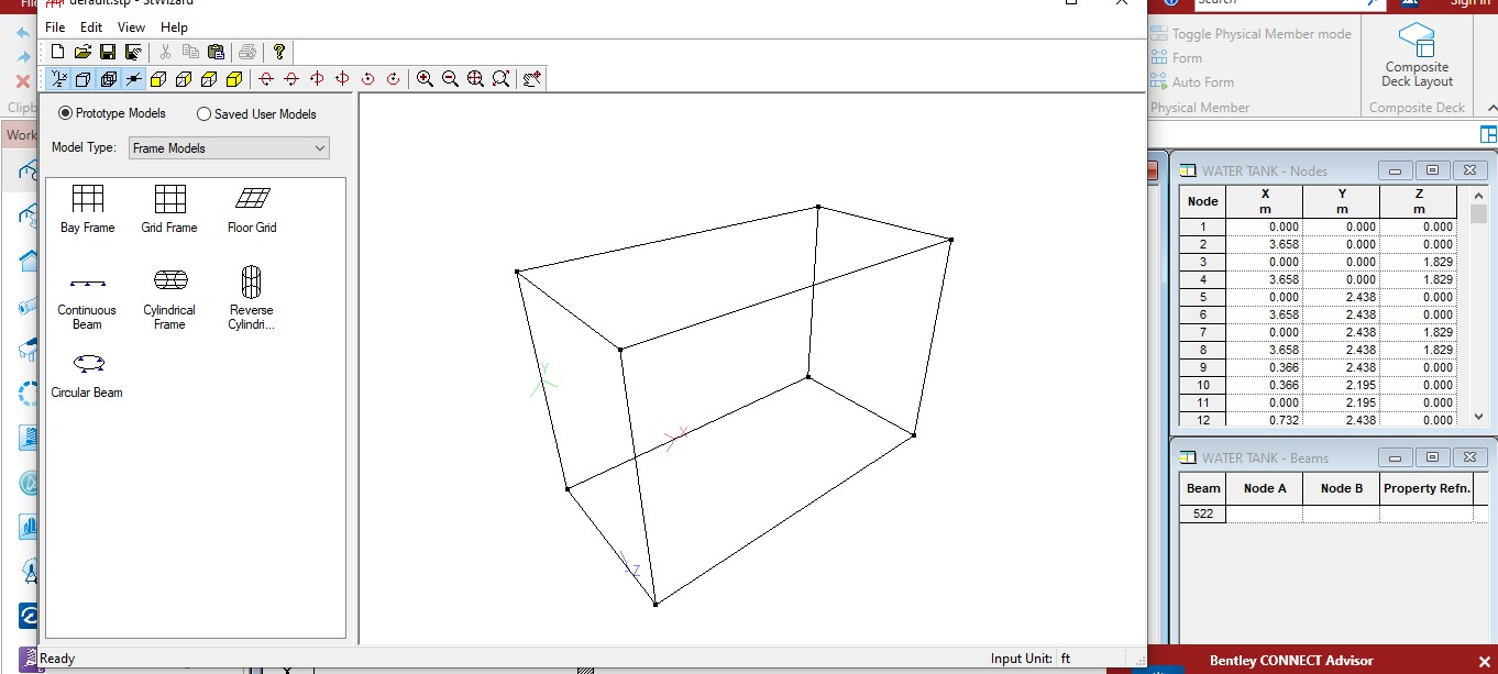
3D Model of Tank
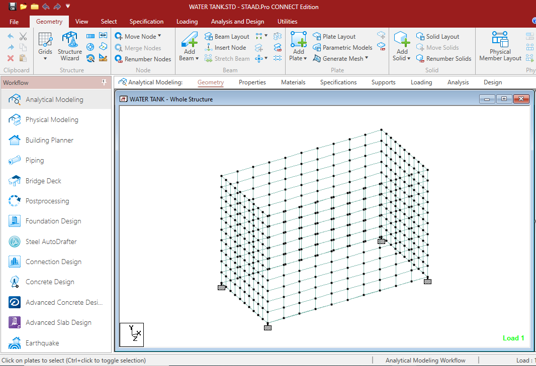
Assign Nodes
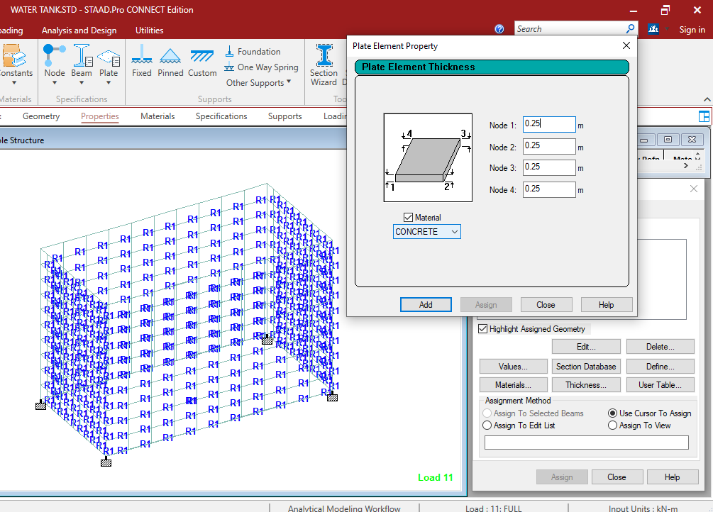
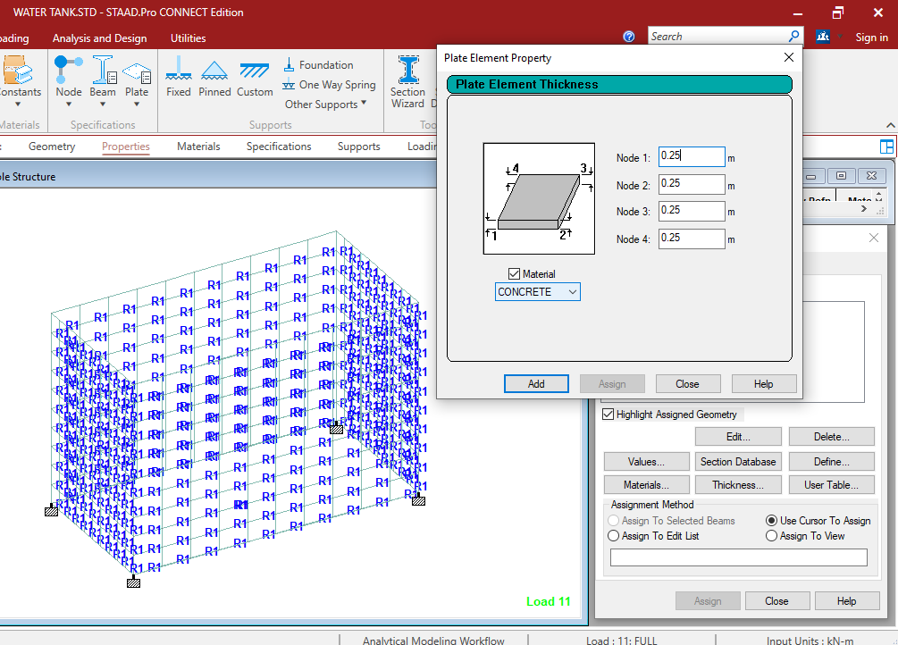
Define the Thickness of Plate
- Assigning of Support
Support Assigning on Tank
- Assign material:
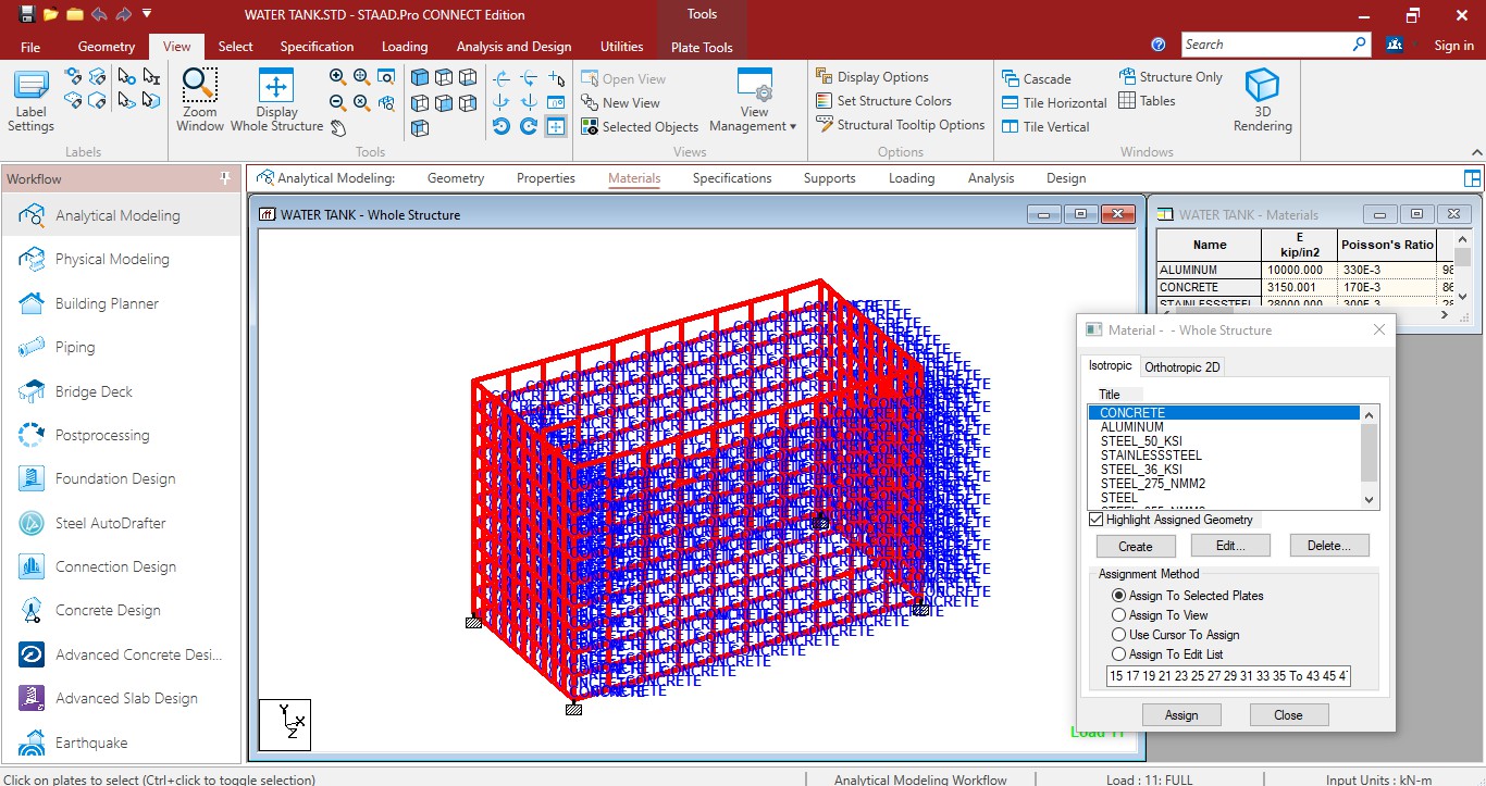
Define Material
Assign Concrete
- Load Creating and Assigning Soil Pressure on Tank:
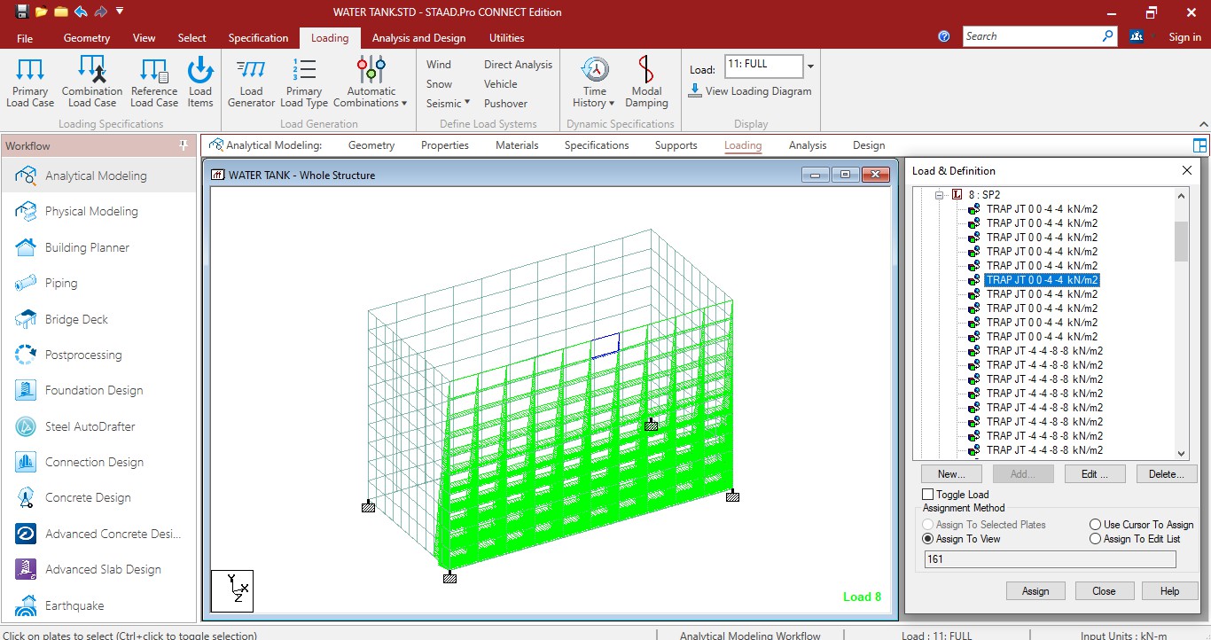
Soil Presure on Tank
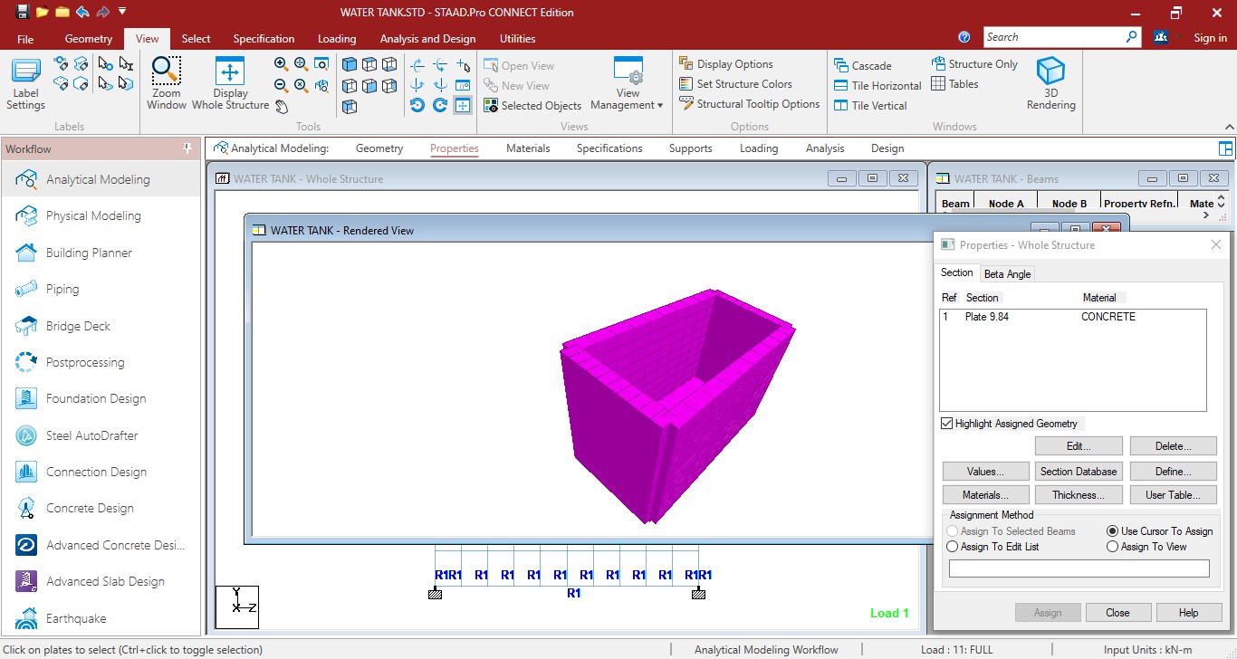
3D Rendering View of Tank
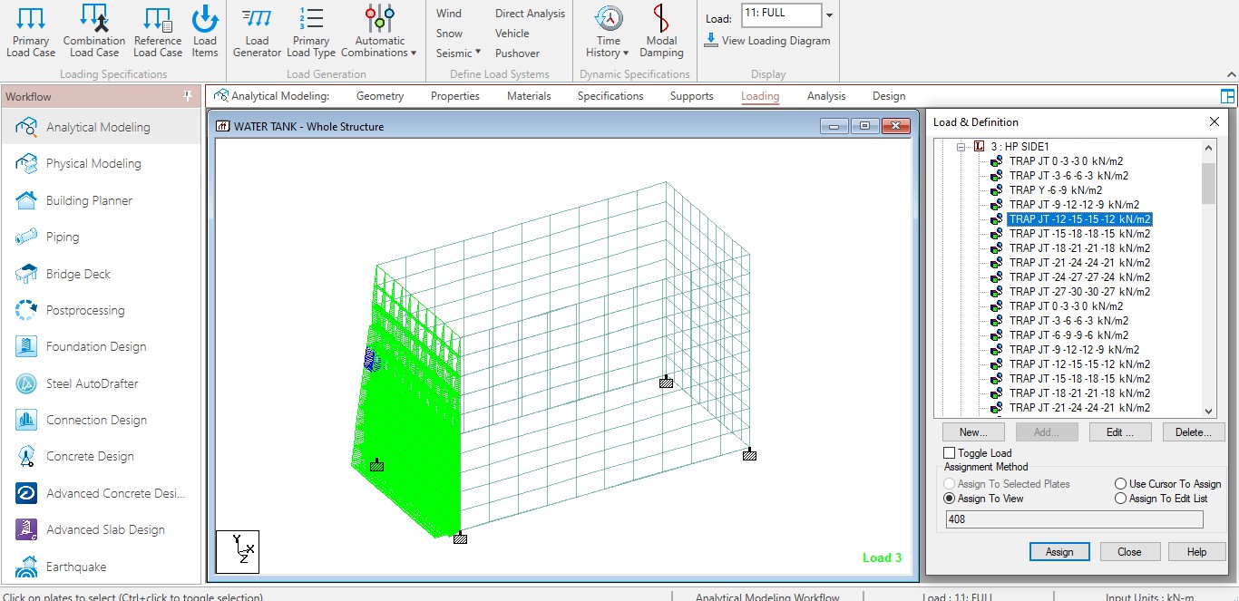 Hydrostatic pressure on tank
- LOAD COMBINATION OF WATER TANK:
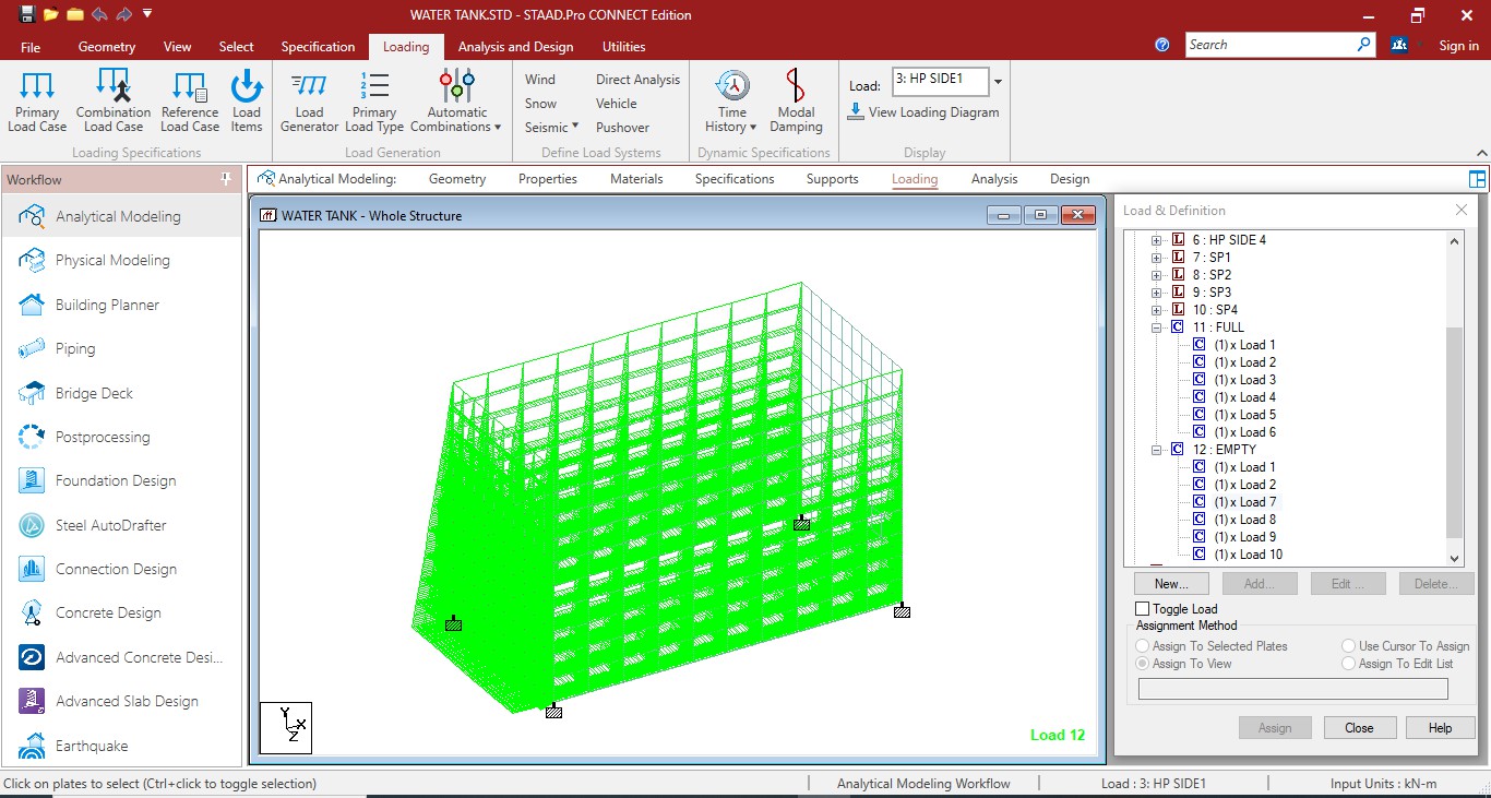
Empty Condition
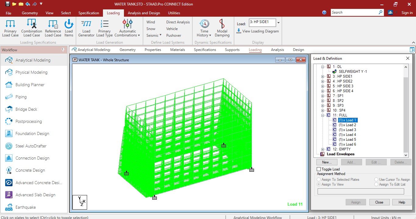
Full Tank Condition
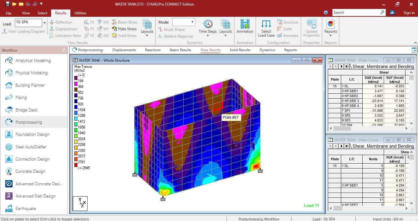
Plate stress in tank
V. RESULT & DISCUSSION
A three-dimensional finite element analysis was performed using STAAD Pro Connect to study the dynamic behavior of underground water tanks under varying load conditions, including empty and full scenarios. The analysis focused on dynamic methodologies, specifically the added mass method, to evaluate the effects of fluid-structure interaction (FSI). Various soil conditions— medium, hard, and soft—were modeled to understand their influence on the tank's response. Multiple models were developed to comprehensively analyze the dynamic performance of underground water tanks and assess the impact of FSI across different soil conditions.
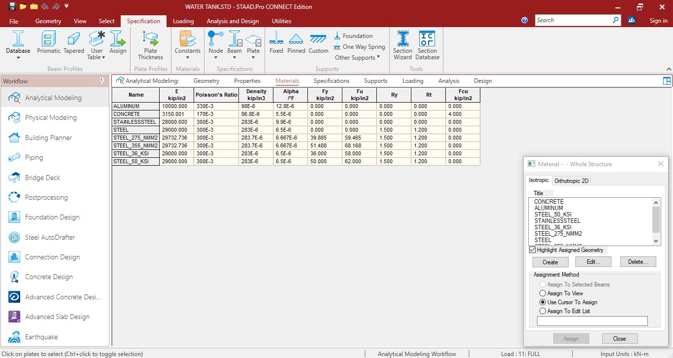
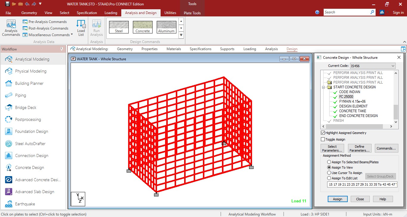
Assign material and IS 456 code
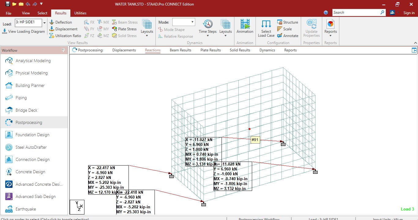
Calculation and assign load on support
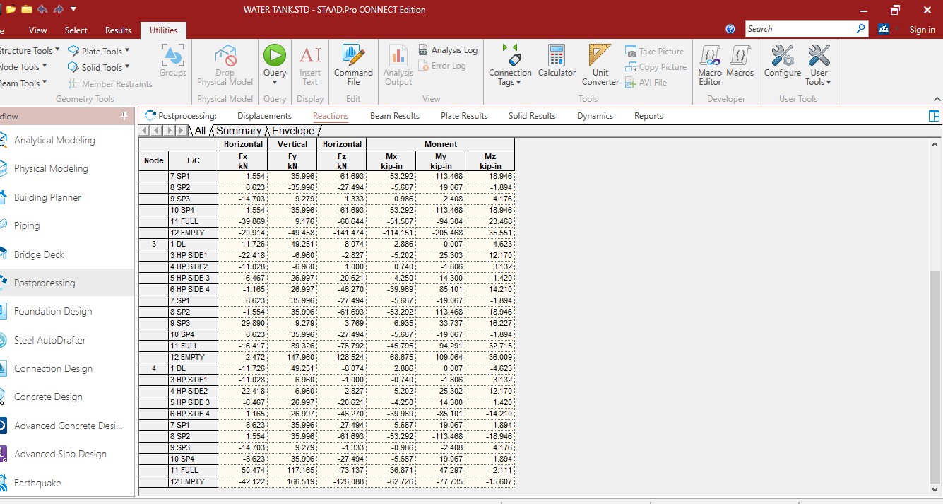
Support reactions
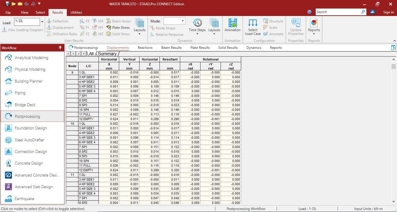
Displacement results on water tank
Bending moment and shear stress result of water tank
a) Area of steel
|
DESCRIPTION |
STAAD RESULT |
|
TOTAL STEEL |
29000 mm2 |
|
STEEL ON EACH FACE |
14500mm2 |
b) Steel required in side wall
|
DESCRIPTION |
STAAD RESULT |
|
Total steel |
5500mm2 |
Conclusion
In conclusion, the dynamic analysis of underground water tanks considering fluid-structure interaction (FSI) has emerged as a crucial endeavor in ensuring the stability, safety, and sustainability of water storage systems. Furthermore, this project has shed light on the environmental considerations, cost implications, regulatory compliance, and lifecycle assessment aspects associated with underground water tanks, providing a holistic understanding of the challenges and opportunities in water infrastructure engineering. 1) Environmental Considerations: Discuss the environmental impact of underground water tanks and the importance of ensuring their structural integrity to prevent potential hazards such as groundwater contamination. 2) Cost-Benefit Analysis: Include a cost-benefit analysis of implementing dynamic analysis techniques for underground water tanks, considering factors such as construction costs, maintenance expenses, and potential savings from improved structural performance. 3) Regulatory Compliance: Highlight the relevance of regulatory standards and codes governing the design and operation of underground water tanks, emphasizing the importance of compliance to ensure public safety and regulatory approval. 4) Lifecycle Assessment: Consider the lifecycle assessment of underground water tanks, including factors such as material selection, construction methods, and end-of-life disposal, to evaluate their overall sustainability and environmental footprint.
References
[1] Subbalakshmi, V., Naveen Kumar, \"Innovative Construction of Combined Ground and Elevated Level Service Reservoir in Single Structure,\" IJAST, Vol. 29, No. 02, 2020. [2] Issar kapadia. Had done the “design, analysis and comparison of underground rectangular water tank by using staad provi8 software” [3] Tirandaz, Aleemuddin, Khannavar, Shameena, Kolhar, M.H., \"Response Spectrum Analysis of Elevated Water Tank,\" IJRET, Vol. 05, Issue 08, August 2018. [4] Swarupa, K. V. L., & Ramakrishna, R. (2017). Performance of Elevated Circular Water Tank in Different Wind Zones. IJSETR, Vol. 06(11). [5] Faltinsen, O., Rognebakke, O., Lukovsky, I., Timokha, A., \"Multidimensional Modal Analysis of Nonlinear Sloshing in a Rectangular Tank with Finite Water Depth,\" Journal of Fluid Mechanics, Vol. 407, 2000. [6] Faltinsen, O., Rognebakke, O., Timokha, A., \"Resonant Three- Dimensional Nonlinear Sloshing in a Square-Base Basin,\" Journal of Fluid Mechanics, Vol. 487, 2003. [7] Frandsen, J. B., \"Sloshing Motions in Excited Tanks,\" Journal of Computational Physics, Vol. 196, 2004. [8] Ibrahim, R. A., Liquid Sloshing Dynamics: Theory and Applications, Cambridge University Press, 2005. [9] Molin, B., Remy, F., \"Experimental and Numerical Study of the Sloshing Motion in a Rectangular Tank with a Perforated Screen,\" Journal of Fluids and Structures, Vol. 43, 2013. [10] Patel, K. (2018). Wind and Seismic Analysis of Elevated Tank Using STAAD Pro. IRJET, Vol. 05(10). [11] Hirt, C., Amsden, A., & Cook, J. (1974). An Arbitrary Lagrangian- Eulerian Computing Method for All Flow Speeds. Journal of Computational Physics, Vol. 14(3), pp. 227–251. [12] Engineering and Technology Journal for Research and Innovation (2022). Seismic Analysis of Underground Tanks Considering Hydrodynamic and Soil Effects. ETJRI, Vol. IV(02) [13] Is code 3370 -1965 code of concrete structure for storage of liquids. [14] Is code 456 -2000 code for plain and reinforced concrete.
Copyright
Copyright © 2024 Shweta Rajoriya, Dr. Raghvendra Singh . This is an open access article distributed under the Creative Commons Attribution License, which permits unrestricted use, distribution, and reproduction in any medium, provided the original work is properly cited.

Download Paper
Paper Id : IJRASET65619
Publish Date : 2024-11-28
ISSN : 2321-9653
Publisher Name : IJRASET
DOI Link : Click Here
 Submit Paper Online

