Ijraset Journal For Research in Applied Science and Engineering Technology
- Home / Ijraset
- On This Page
- Abstract
- Introduction
- Conclusion
- References
- Copyright
Dynamic Load Analysis of Mine-Truck Using Multibody Dynamic Analysis Method
Authors: Parag Manohar Mahajan, Pradip Bhaskar Jasud
DOI Link: https://doi.org/10.22214/ijraset.2024.58955
Certificate: View Certificate
Abstract
Vehicle load distributed on front & rear axle assembly during various working conditions is one of the most important factors influencing working performance and service life of drive axle assembly. The dynamic load on axle assembly is higher compared to the rated load because of variations in vehicle speed and road surface conditions. Early failure of structural components is caused because of higher dynamic reaction forces due to uneven road profiles. The dynamic load calculation of axle assembly is presented in this paper for a Mine-truck with various road conditions and vehicle speeds. The road load conditions consist of grade, bump & path hole. Mine-truck with payload capacities of 63 Ton is considered for the study. The behaviour of vertical force is calculated for different vehicle speeds (3 - 12 km/hr.) of the machine on the front & rear axle assembly during running conditions. Multi-body dynamic Analysis tool ADAMS is used for this study. ADAMS helps to study the dynamics of moving parts and load distribution throughout mechanical systems during motion. The Mine-truck3D model was created with the help of computer-aided design (CAD) software. Major units of Mine trucks are considered to prepare 3D models like Cabin-engine mass, Bucket, front axle assembly, rear Axle assembly & tires. Multi-body vehicle models are prepared in simulation software ADAMS by importing 3D models prepared by computer-aided design (CAD) software. This provides guidelines for selecting dynamic load factors while designing structural parts of the vehicle.
Introduction
I. INTRODUCTION
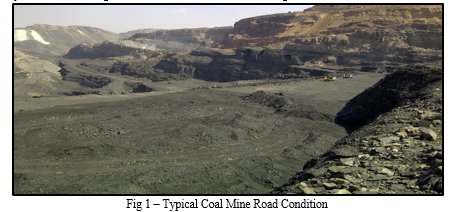
The axle assembly is the main load-carrying member of the off-highway vehicle. Vehicle load distributed on front & rear axle assembly during various working conditions is one of the most important factors influencing working performance and service life of drive axle assembly. Load distribution on the wheel is based on its operating condition [1]. Reaction force on one wheel is a key parameter that is used for the design of a vehicle. This one-wheel load depends on gross vehicle weight (GVW), speed, wheelbase, and Centre of gravity location of the vehicle. The dynamic load on axle assembly is higher compared to the rated load because of variations in vehicle speed and road surface conditions. The road condition of the Mines is severe with path holes, sand, and gravel. Figure 1 shows Typical Coal mine road conditions.
The mining dump truck runs all year round on the terrible mine road, which is prone to need higher performances than the general highway vehicle, such as stiffness, strength, and fatigue life [2]. This study is useful to avoid the early failure of the Mine-truck axle by determining the dynamic load coming on the wheel due to road surface roughness.
Joubert et al. (2020) presented a study on semi-analytical & full analytical methods to predict the vehicle frame loads using Multibody Dynamic simulation, considering the single-wheel ramp, downhill ramp & hard braking conditions on vehicles using SimPackTM [2]. Lu et al. (2009) reported a Numerical and experimental investigation on a stochastic dynamic load of a heavy-duty vehicle, Analysis of dynamic load is carried out with the help of software ADAMS [3]. Cheli et al. (2011), mentioned a study on Tire-road contact forces determined through finite element analysis (FEA) and verified through experimental tests, vehicle dynamics results are significantly affected due to Tire-road contact forces [4]. Zheng et al. (2014), reported the Failure analysis of the Mining dump truck frame, considering the various path holes, obstacles, slope and curves on the bumpy road by combing the FEA, as well as static and dynamic testing [5]. Zhang et al. (2021), reported a practical approach to estimating the vertical tire forces of a multi-axle truck for dynamic control. MATLAB/Simulink and Trucksim software are used, which can simulate a real truck used in the heavy vehicle industry [6]. Guan et al. (2018) reported the use of MSC ADAMS software for pavement design based on a multi-rigid-body dynamics model to calculate the force & displacements [7]. Mi et al. (2012) used the finite element method and multibody dynamic analysis to predict the fatigue life of mining dump trucks. Multibody dynamic analysis & finite element analysis are done by combined use of software ADAMS, SolidWorks, Hyper mesh, and MSC. Fatigue [8].
The present research work is different from the above-cited works. The overall objective of this research is to calculate the dynamic load on the vehicle axle assembly, considering the effect of speed, and road condition with a 63Ton payload capacity of Mine-trucks. The dynamic load on front and rear axle assembly is calculated for various road conditions and a 63-ton payload capacity truck.
Vertical tire forces are essential in vehicle modelling and dynamic control. Two types of methods, i.e., a direct measurement and an estimation, can be used to evaluate the vertical tire forces. The costs of a direct measurement are high, whereas the estimation method requires more sensors to ensure the accuracy, in this research vertical dynamic load on the vehicle is calculated by using the virtual model in MSC.ADAMS [9].
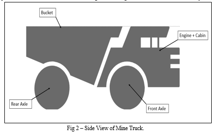
Figure 2 shows the side view of the Mine Truck. Major units of the Mine Trucks are material carrying bucket, engine and cabin, Front Axle assembly and rear Axle assembly. The bucket is located at the rear of the truck. The engine & cabin is in front of the truck. The payload placed on the bucket is transferred to the ground through the Front & rear axle assembly of the truck.
A parametric virtual prototype of a Mine-truck is created in the simulation package MSC.ADAMS [9]. ADAMS helps to study the dynamics of moving parts, and load distribution throughout mechanical systems during motion. A mine-truck with a payload capacity of 63 Tons is used for analysis. Vehicle speeds ranging from 3 to 12 km/hr are used. Various road conditions like ramps, path holes, and cross bumps are used for analysis. A moving vehicle is a complex nonlinear vibration system with multiple degrees of freedom, but a simplified model is used to perform analysis because our objective is to calculate only wheel reaction forces during the moving condition, besides Mine-truckdoes not have any suspension linkages like leaf springs or Dampers to absorb the shock from the road surface.
II. MATERIALS AND METHODS
A. Underground Mine-truck specifications:
Specifications of 63T payload capacity A Mine-truck is used to perform multibody dynamic analysis, key Parameters of the truck according to payload capacity are listed in below Table 1, (Sandvik, 2022) [10].
Table 1 – Technical Specifications of Mine-Truck
|
Truck |
|
|
Pay Load Capacity (Ton) |
63 |
|
Empty Vehicle weight (kg) |
48,440 |
|
Gross vehicle weight (kg) |
111,440 |
|
Wheelbase (mm) |
5650 |
|
Static Tire rolling Radius (mm) |
979 |
B. Modelling of Truck
Mine-truck 3D model has been created with the help of computer-aided design (CAD) software. Major units of Mine-truck are considered to prepare 3D models like Cabin-engine mass, Bucket, front axle assembly, rear Axle assembly & tires. The overall dimensions of the mine truck are considered from the product brochure (Sandvik, 2022) [10]. Multi-body vehicle model has been prepared in simulation software ADAMS by importing a 3D model prepared by computer-aided design (CAD) software. The densities of each unit of Mine trucks are adjusted to match the Front axle and Rear axle assembly load with the brochure. This is used as an empty vehicle model for further multibody dynamic analysis. Bucket density adjusted to consider external payload on Mine Truck. It is assumed that extra payloads are equally distributed over the bucket.

The Front axle and rear axle are attached to the Cabin & bucket through fixed joint respectively. The revolute joint is used to connect the Tire & axle.
C. Modelling of tire & Road Profiles:
The Tire of Mine-truck acts as a suspension device between the vehicle & road surface which absorbs the shock from the road. Tire is a very critical parameter in the multibody dynamic analysis because of its variable stiffness. Tire stiffness depends on the inflation pressure, material (rubber) properties, type & configuration [3]. ADAMS Fiala Tire (FT) is selected from the standard library of ADAMS [11]. The Fiala Tire model is a physical tire model in which the tire carcass is modelled as a beam on an elastic foundation in the lateral direction. The tire belt ply or buffer layer is simplified as a section beam acting under concentrated load. The model is very simple and does a fair job of representing general tire force and moment curves, which is verified by experiments by ADAMS [11]. The main advantage of the ADAMS Fiala Tire (FT) is that only a few parameters are required, The vertical stiffness and damping of the tire are specified as input parameters. Tire size and dimensions are selected from Mine-truck specifications for preparing tires in the simulation software ADAMS.
During the vehicle life, dynamic forces caused by the road roughness produce dynamic stresses and these forces lead to fatigue failure of axle, which is the main load carrying part of the assembly. Therefore it is vital that the axle resist against the fatigue failure for a predicted service life [12].
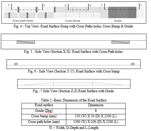
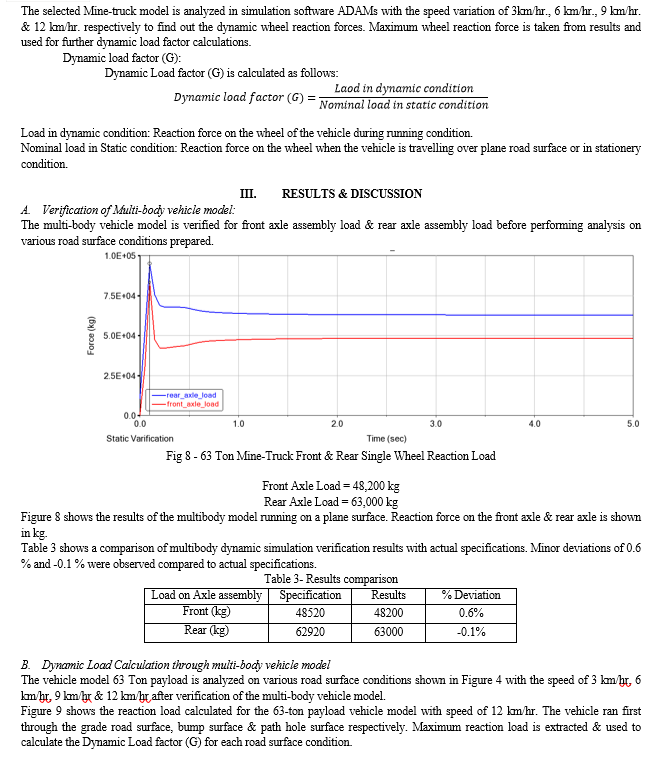
The road condition of the Mines is severe with path holes, sand, and gravel. This is because of the unpaved mine road surface [5]. Generally, any vehicle during its operation goes through grade, path hole & bump conditions. Various road surface designs are prepared to consider the effect of grade, path hole & bump during simulation. Figure 4 shows the top view of the Road surface model inside the simulation software ADAMS. 3D road format is created in ADAMS. It consists of path holes, bumps & grades. Path holes and bumps are located at alternate distances so that both wheels of the same axle will not have hurdles at the same time. This simulates severe load conditions. Path holes and bumps simulate the condition of big pits and gravels of actual mines. Figures 5, 6 and 7 show cross-sections of cross-path holes, cross bumps, and grades respectively. Table 2 shows the Basic dimensions of the road surface
IV. ACKNOWLEDGMENT
The authors would like to thank Dana Incorporated management and Head of Department Paul Sanjay and Umesha Gangarudraiah for their continuous support and encouragement.
Conflict of Interest statement:
On behalf of all authors, the corresponding author states, the authors have no financial or proprietary interests in any material discussed in this article.
Conclusion
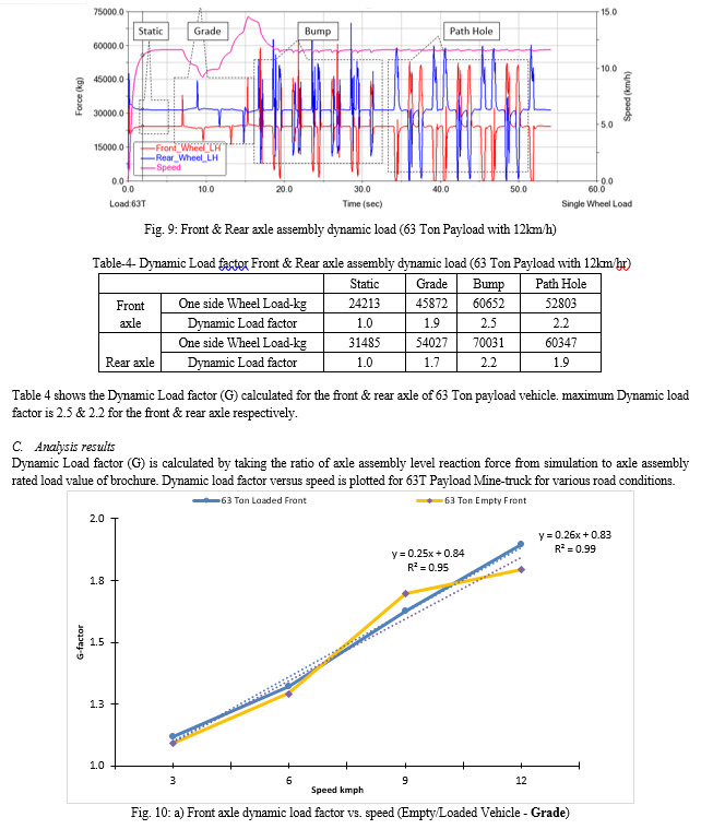
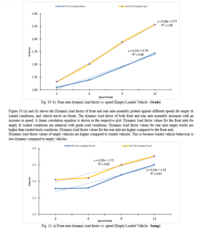
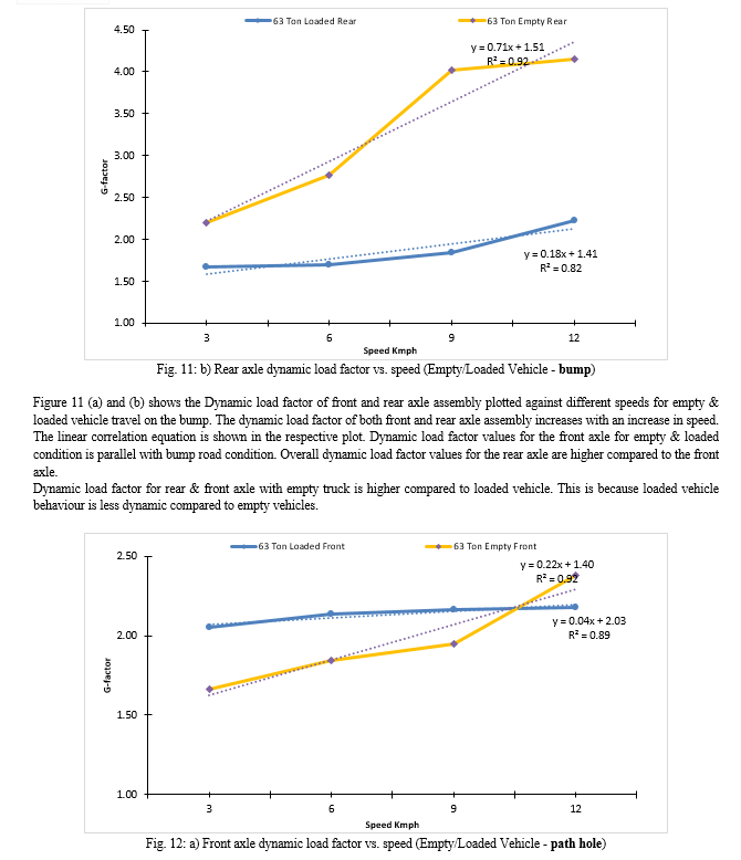
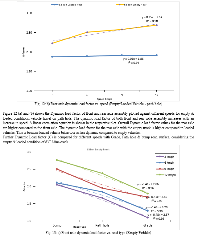
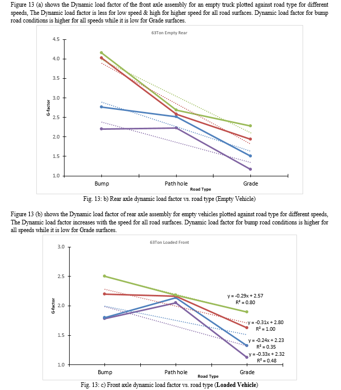
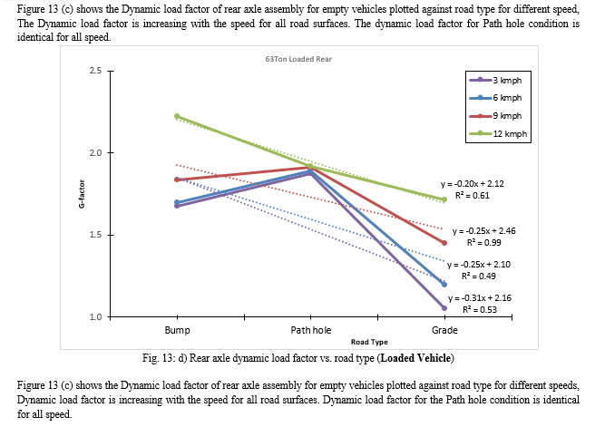
1) Dynamic Load factor of a Mine-truck increases as speed increases. 2) Linear correlation equations are developed which can be used to calculate the G-factor at any speed of a Mine-truck for respective road surface conditions. 3) Dynamic load factor values in the case of 4) the front axle is higher compared to the rear axle assembly while the truck is travelling over a graded road surface. This is because of the dynamic effect of centre of gravity of a truck while travelling on graded road surface. 5) Dynamic load factor values of empty vehicles are higher compared to loaded vehicles. This is because, loaded vehicle behaviour is less dynamic compared to empty vehicles, also due to the uncertain body bounce generated by the truck.
References
[1] G. W. Burkett, J. T. McDonald, and S. A. Velinsky: Dynamic Road Load Simulation of Transportable Cranes: Mechanics Based Design of Structures and Machines. An International Journal. 32:3, 329-362, (2007). https://doi.org/10.1081/SME-200027957 [2] N. Joubert, M. Boisvert, C. Blanchette, Y. St-Amant, A. Desrochers, D. Rancourt: Frame loads accuracy assessment of semi-analytical multibody dynamic simulation methods of a recreational vehicle. Multibody System Dynamics. 50:189–209, (2020). https://doi.org/10.1007/s11044-020-09756-8 [3] Y. Lu, S. Yang, S. Li, L. Chen: Numerical and experimental investigation on stochastic dynamic load of a heavy-duty vehicle. Applied Mathematical Modelling. 34:10, 2698–2710, 2010. https://doi.org/10.1016/j.apm.2009.12.006 [4] F. Cheli, F. Braghin, M. Brusarosco, F. Mancosu, E. Sabbioni: Design and testing of an innovative measurement device for tyre–road contact forces. Mechanical Systems and Signal Processing. 25, 1956–1972, (2011). https://doi.org/10.1016/j.ymssp.2011.02.021 [5] S. Zheng, K. Cheng, J. Wanga, Q. Liao, X. Liu, W Liu: Failure analysis of frame crack on a wide-body mining dump truck. Engineering Failure Analysis. 48, 153–165 (2015). http://dx.doi.org/10.1016/j.engfailanal.2014.11.013 [6] B. Zhang, T. Xu, H. Wang, Y. Huang and G. Chen.: Vertical Tire Forces Estimation of Multi?Axle Trucks Based on an Adaptive Treble Extend Kalman Filter. Chinese Journal of Mechanical Engineering. 34:55, (2021). https://doi.org/10.1186/s10033-021-00559-2 [7] Z. Guan, J. Feng, Q. Wu, P. Zhang.: Mechanical analysis of full-scale accelerated pavement loading facility based on multi-body dynamics. Systems Science & Control Engineering 6:1, 528-536, (2018). https://doi.org/10.1080/21642583.2018.1547883 [8] C. Mi, Z. Gu, Q Yang, D. Nie: Frame fatigue life assessment of a mining dump truck based on finite element method and multibody dynamic analysis. Engineering Failure Analysis 18–26, (2012). https://doi:10.1016/j.engfailanal.2012.01.014 [9] MSC Software - ADAMS/Car [EB/OL], Version 2003. https://www.mscsoftware.com/product/adams, Accessed 10 September 2022 [10] 63 Ton Payload Mine-truck specifications https://www.rocktechnology.sandvik/en/products/equipment/trucks/th663i-underground-truck/ Accessed 15 September 2022. [11] Adams 2021.4 Adams Tire User\'s Guide https://help.hexagonmi.com/bundle/Adams_2021_Adams_Tire_User-s_Guide/resource /Adams_2021_Adams_Tire_User\'s_Guide.pdf Accessed 20 September 2022. [12] M. Lal, R. Kulkarni, P. Makasre, L. Kamble.: Fatigue Analysis of Front Axle for Automobile Heavy Motor Vehicle : ISSN: 2321-9653; IC Value: 45.98; SJ Impact Factor: 7.538 Volume 11 Issue IV Apr 2023- https://doi.org/10.22214/ijraset.2023.50660
Copyright
Copyright © 2024 Parag Manohar Mahajan, Pradip Bhaskar Jasud. This is an open access article distributed under the Creative Commons Attribution License, which permits unrestricted use, distribution, and reproduction in any medium, provided the original work is properly cited.

Download Paper
Paper Id : IJRASET58955
Publish Date : 2024-03-12
ISSN : 2321-9653
Publisher Name : IJRASET
DOI Link : Click Here
 Submit Paper Online

