Ijraset Journal For Research in Applied Science and Engineering Technology
- Home / Ijraset
- On This Page
- Abstract
- Introduction
- Conclusion
- References
- Copyright
Effect of Submerged Arc Welding (Saw) Parameters on Aisi 1020 Steel
Authors: Hemant Panchal, Ishan Yadav, Harshil Variya, Prakashchandra Tiwari, Yash Tandel
DOI Link: https://doi.org/10.22214/ijraset.2024.64851
Certificate: View Certificate
Abstract
This research investigates the Submerged Arc Welding (SAW) process applied to AISI 1020 steel plates (450 mm x 300 mm, 12 mm thickness). A V-groove shape was prepared for welding using Tungsten Inert Gas (TIG) rooting. To achieve optimal results, welding parameters such as current, voltage, and travel speed were optimized. Following this experimentation phase, parameter selection was guided by a comprehensive literature review. Microstructure observations for the welded bead, Heat-Affected Zone (HAZ), and base metal were then reviewed in the existing literature, highlighting this study\'s unique focus on parameter optimization. The findings provide valuable insights for industries relying on welded components, enhancing quality and reliability in AISI 1020 steel welding applications.
Introduction
I. INTRODUCTION
The main objective is to confirm the power source type employed during the Submerged Arc Welding (SAW) process, typically opting for a Constant Voltage source for consistent arc length, though occasionally using a Constant Current source despite its challenges. It has been meticulously monitor and quantified parameter changes following adjustments in welding current and voltage, assessing the welding speed to ensure accurate heat input calculation for optimal weld quality. Studying the behaviour of AISI 1020 mild steel under welding conditions reveals significant changes in its properties, necessitating examination before and after welding, including preheating and post-welding treatment. Conducting a failure analysis verifies the mechanical properties for manufacturing, with testing outcomes guiding optimal welding parameters. Examining various sections of the sample plate, including the base metal, heat-affected zone, and weld bead, demonstrates the welding process's effectiveness, requiring individual analysis of each area's properties and structure.
The obtained result will provide an optimum range of welding parameters which can be used for a 12 mm Mild Steel Plate (AISI 1020). These references can be helpful to fasten the welding process needed for a large quantity of specimens along with a good weld quality. Mostly Low Carbon Steels and Alloy Steel are welded by SAW process. Furthermore, SAW is Automated and Semi-Automated which reduces the percentage of error in work and doesn’t demand any hassle work. Also, it is best if large numbers of products are needed to manufacture in short time period. The post welding property analysis will provide the best information regarding the required purpose of the specimen and its usage. A more defined application will require a systematic manufacturing of the product.
The study focuses on Submerged Arc Welding (SAW), predominantly utilizing CV (Constant Voltage) power source due to the continuous wire feed, which makes maintaining a constant current (CC) impractical. Researchers aim to address common issues identified in literature such as penetration, lack of diffusion, spattering, and burn-through, seeking effective solutions. Post-weld, the material strength will be tested, evaluating the compositional changes influenced by flux interaction during SAW. The investigation also includes analysing how changes in polarity and heat input affect the deposition rate in the weld bead. Additionally, meticulous attention had given to sample preparation, including groove cutting and preheating requirements, ensuring accurate experimental conditions.
II. LITERATURE
A. Welding
Welding is one of the most essential and inescapable process used for major fabrication and sculptures process in the Manufacturing industries. Welding is a process that joins materials, usually metals or thermoplastics, by causing coalescence generated by with or without pressure and with or without temperature.
This is frequently done by melting the work pieces and adding a filler material to form a loch of molten material (the weld pool) that cools to become a strong joint, with pressure sometimes used in conjunction with heat, or by itself, to produce the weld. [1]
1) Welding Process Comprises of following steps:
- Preparation – Cleaning of surface from contaminations and ensuring the alignment of the piece to be welded.
- Heat Source – Mainly by Arc and Flame.
- Shielding – Shielded area is created by gas or flux.
- Filler Material – The process can consume electrode or no filler wire is required.
- Welding Process – Manipulation in the technique for welding and variables in the parameters.
- Cooling & Solidification
- Inspection & Finishing [1]
2) Selection of Welding Process: The weld, ideally, should achieve continuity between the part being joined in such a way that the weld joint is indistinguishable from the base metal from which it is joined. However, it is impossible to achieve such an ideal situation, but a satisfactory weld can be produced by choosing a more appropriate welding process and parameters. Some of the critical factors which must be duly considered while selecting the welding process are:
- Type of metal and its metallurgical characteristics
- Type of joint, location, and welding position
- End-use of joint and expected performance
- Joint design, accessibility, and accuracy required
- Structural size
- Cost of production [2]
B. Submerged Arc Welding(SAW)
A continuous, uncoated wire electrode serves as a filler material, extending to the joint to produce an arc. Granular flux is supplied by a hopper to submerge the arc. The electrode must have low electrical resistance for proper high-current welding. In the cavity where the metal arc burns, the base metal melts and fluidizes, with solidified weld metal forming at the back. Molten flux reacts with impurities, forming a light slag that floats on top and solidifies into a removable layer. The partially used granular flux is reclaimed for reuse. [3]
The process includes continuously feeding electrodes. The molten weld and the Arc zone were prevented by atmosphere by being submerged under the cover of granular fusible flux. [4] Weld quality includes the weld bead dimensions, temperature distribution, metallurgical phases generated in the weld pool and the heat-affected zone (HAZ), and mechanical properties of the weldment. The welding conditions involved in the SAW process include welding current and voltage, polarity, electrode extension and diameter, welding speed, and type of granular flux. [5] In the automatic version of SAW, the process is performed with a set of rollers driven by a controlled motor to ensure that the wire is fed into the arc at a speed rate that is equivalent to the rate at which the electrode is melted. The arc length remains constant as a result. The SAW process is usually automated; however, there are semi-automated systems available, too. [6]
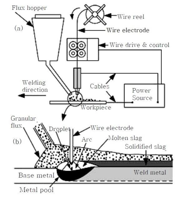
Fig.1 Submerged Arc Welding Schematic Diagram [6]
C. Welding Parameter in SAW
In the welding process, various factors influence the quality and characteristics of the weld. Electrode polarity affects penetration and surface appearance, with DC reverse polarity offering the deepest penetration and best resistance to porosity, while DC straight polarity provides faster burn-off and is suitable for steels with limited weldability. Welding current, controlled by wire feed speed, determines deposition rate and penetration depth, with both low and high current densities potentially causing instability. Electrode diameter impacts current density, where larger diameters reduce penetration but complicate arc striking and stability. Arc voltage governs arc length, flux consumption, and weld metal properties, increasing bead width and alloying element entry without significantly affecting penetration. Welding speed controls penetration depth, where faster speeds reduce bead width and increase porosity risk, while slow speeds can lead to burn-through and solidification cracks. Lastly, Electrode extension alters resistance heating, with longer extensions reducing penetration but increasing deposition rates, necessitating careful guidance to avoid wandering. [6]
D. Variants of SAW Process
- Welding Wire: The multi-wire SAW process, including twin-wire and multi-wire variants, boosts welding productivity for medium to high-thickness plates. In twin-wire SAW, two small diameter wires share a single power source, increasing current density and arc interaction, thus enhancing the deposition rate compared to single-wire SAW. [7] The welding wire typically matches the composition of the parent metal and is available for carbon, low and high alloy steels, stainless steels, and nickel and copper/nickel alloys. Submerged arc welding can use wires or flat strips for surfacing with corrosion or wear-resistant coatings. Wires, solid or metal-cored, range from 1.2mm to 6.4mm in diameter, handling currents from 150 to 1600 ampere. [6]
- Fluxes: It play a crucial role in Submerged Arc Welding (SAW), similar to the coating in stick electrodes, by shielding the weld pool from inactive gases and influencing weld metal composition through reactions. Hygroscopic fluxes are often baked to remove moisture, while fused and agglomerated fluxes consist of oxides and halides like MnO, SiO2, CaO, and Na2O. These fluxes can be basic or acidic, affecting the basicity index and thus the weld properties. In the SAW process, flux melts and forms a slag layer over the weld pool, preventing oxidation and cleaning the weld. Various flux constituents have distinct effects: SiO2 increases penetration and arc stability, MnO2 reduces rust sensitivity and porosity, CaO enhances arc stability, NiO improves impact properties, and TiO2 promotes acicular ferrite formation and impact strength. Overall, flux composition profoundly impacts weld characteristics in SAW. [8]
Submerged Arc Welding (SAW) offers versatile welding techniques tailored to different applications, including flat, horizontal, vertical, and overhead positions. [9] Welding can be performed in three different conditions i.e., the backhand with 45 degree electrode angle, forehand/backhand with 90degree electrode angle, and forehand with 45 degree electrode angle in SAW process. [10]
TABLE 1
SAW MERITS & DEMERITS [11]
|
Advantages |
Disadvantages |
|
The capability of deep weld penetration. |
Cannot apply to direct seams vessels and pipes. |
|
Emits minimal welding fume or arc light or no weld spatter. |
Proper root penetration requires backing strips. |
|
High deposition rates (over 45 kg/h (100 lbs/h). |
Impractical to use in vertical or overhead welding positions. Principally used for butt welds (flat position-1G) and fillet welds (flat/horizontal position-1F/2F). |
|
Single-pass welds can be made in relatively thick plates if conditionally acceptable. |
Limited to some particular metals i.e. ferrous or some nickel-based alloys. |
|
Imparts high-speed welding of thin sheet steels up to 5 m/min (16 feet/min). |
Requires inter-pass and post-weld slag removal. |
|
No high level or edge training is required. |
Slag elimination is desirable after welding. |
Submerged Arc Welding (SAW) is applied for welding various materials such as carbon steel, aluminium, titanium, and alloys. It is particularly effective for creating joints in corrosion-resistant metals, heat-resistant steels, and carbon steels, including,
Monel and Nickel. SAW is commonly used in down hand welding applications with plate thickness ranging from 5 to 50mm. Industries such as pipe welding, structural manufacturing, vessel construction, storage tanks, and shipbuilding extensively utilize SAW. Different grades of wires and fluxes, ranging from three to nine, are employed for welding basic steels, high-tensile steels, low-alloyed steels, tubes, and stainless steels across various applications. [12]
During submerged arc welding, various defects may arise, such as insufficient penetration, burn-through, porosity, surface pock marks, arc blow, reinforcement rollover, undercut, and slag inclusion. These issues stem from factors like improper settings, joint contamination, or moisture. Remedies include adjusting current, voltage, travel speed, and flux type, along with proper joint preparation and alignment.[13][14]
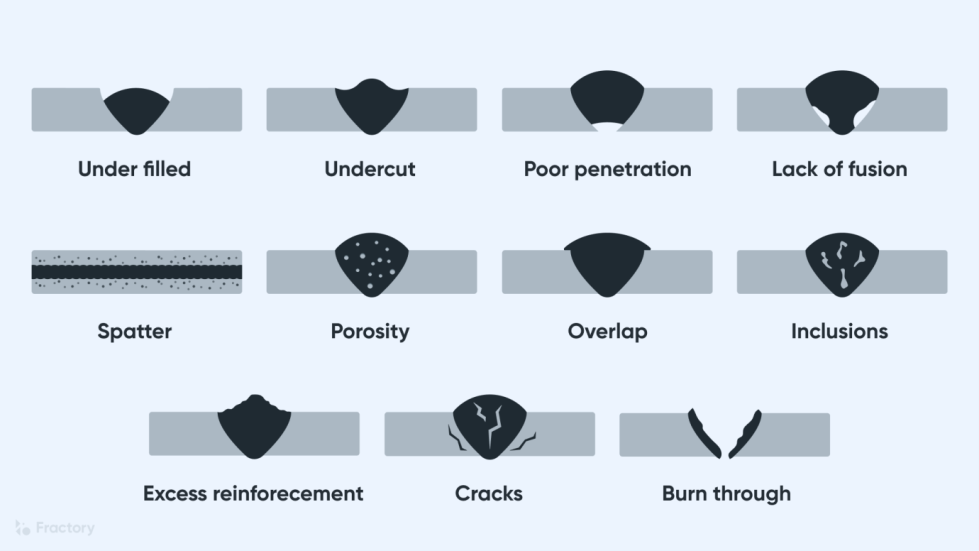 Fig.2 Defects in SAW [15]
E. Optimum Parameters from Literature Study
Majorly Welding Parameters include Welding Current, Heat Input, Welding Speed, Depth of Penetration, Welding Voltage, Inter-pass Temperature and many others variables. Below here is the table of parameters established on the basis of different literature research study. These parameters are only effective for 12mm thick Mild Steel Plate. Also to take into account that the working environments are considered to be general daily basis and not so drastic causing damage to the specimen.
TABLE 2
OPTIMUM PARAMETERS [16][17][18]
|
Parameters |
Value |
|
Welding Current |
450-550 Amp |
|
Welding Speed |
100-1500 mm/min |
|
Welding Voltage |
25-45V |
|
Interpass Temperature |
150-200 Degree Celsius |
|
Stick Out |
25-31 mm |
|
Wire Feed Rate |
500-4000 mm/min |
F. Microstructural Features from Literature Study
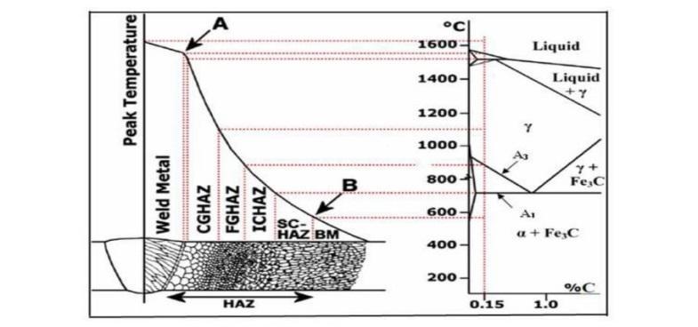
Fig.3 Expected Microstructure of Mild Steel Plate Post-Welding [19][20]
The weld's microstructure is influenced by its cooling rate, base metal composition, and flux. After cooling, the weld undergoes polishing, etching, and observation, revealing three main zones: the heat-affected zone (HAZ), weld metal zone (WM), and unaffected base metal (BM). [19] The area between the weld and the base metal is called the heat-affected zone (HAZ). Its microstructure depends on the peak temperature and time spent in the 800ºC - 500ºC range, ranging from thin zones of martensite to coarse pearlite zones. A schematic in figure depicts the iron-carbide phase diagram and the HAZ of a low carbon steel weld, dividing it into four microstructural zones: grain growth (1450 to 1100 ºC), recrystallized (1100 ºC to A3), partially transformed (A3 to A1), and tempered zones (below A). Additionally, the HAZ subdivides into coarse grained (CGHAZ), fine grained (FGHAZ), inter-critical (ICHAZ), and sub-critical (SCHAZ) zones. [20]
III. EXPERIMENTAL
A. Methodology of the Process
Mild steel AISI 1020 12 mm thickness plate was optimized for the process parameters of welding current, heat input, travel speed and welding voltage on weld bead thickness and bead hardness. [21]
- Identification of Process Variable
- Development of Process Plan
- Raw Material Procurement & Analysis
- Experimental Setup
- Sectioning & Joint Preparation
- Conducting Experiment as per Plan
- Recording the parameters
- Material Testing & Analysis
- Result & Conclusion
B. Joint Preparation
Joint preparation varies based on plate thickness, type of joint, and structural standards. Plates up to 14 mm thick may not require preparation if the gap is within 1mm or 10% of the thickness. Thicker plates need preparation for full penetration. While welders can adjust their technique for varying gaps and root faces, automatic welding heads require precise conditions. Clean plate edges are essential to avoid defects like porosity and cracking, which can be costly to rectify. Thus, investing time in careful joint preparation and inspection is crucial to prevent expensive rework. [6]
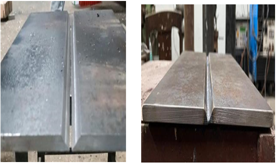
Fig. 4 V-Groove Grinding Fig.5 Joint Preparation
C. Equipment’s used in SAW
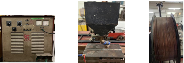
Fig.6 Power Source Fig.7 Welding Gun & Its Angle Fig.8 Electrode Spool
- Power Source: SAW operates with either DC or AC power sources, typically using a transformer-rectifier for DC and a transformer for AC. Current for a single wire range from 200A to 1000 A, with most welding done on thick plates using a 4.0 mm diameter wire at 600 to 900 A, or a twin wire system at 800 to 1200 A. In DC operation, the electrode is usually positive, but negative polarity (DCEN) can increase deposition rate while reducing penetration.DC power sources have a ‘constant voltage’ output, regulating the arc by wire feed speed and voltage. AC sources have a constant-current output, with arc control by sensing voltage to adjust wire feed speed. [6]
- Welding Gun & Its Angle: SAW can be manual or mechanized, with mechanized welding being more common due to its high deposition rates. In manual welding, the welding gun resembles a MIG gun, with flux replacing shielding gas. Flux is fed either through air pressure or a hopper mounted on the gun. While portable, manual welding requires less skill as the operator guides the gun along the joint, making it suitable for short runs and simple operations. For larger components, the equipment can be mounted on a rail, tractor, or boom manipulator. Single wire welding typically uses DCEP, though AC can be used to address arc blow issues. [6]
- Electrode Extension: To control wirestick out in SAW, it’s crucial to consider its impact on wire preheating and burn-off rate. Increasing stick out can significantly boost deposition rates, such as from 9 kg/hr to 14 kg/hr for a 4mm wire at 700A. However, long stick outs are typically reserved for cladding and surfacing to manage penetration and deposition. In most cases, the electrode stickout is set to ensure the contact tube slightly protrudes above the flux layer, with enough flux depth to cover the arc while allowing its light to be visible. [6]
- Flux: should be stored in a humidity-controlled environment and dried according to the manufacturer's guidelines if it's been opened and stored. In small welding setups, flux is typically stored in a hopper above the welding gun and fed automatically. Larger installations use compressed air to feed flux from large hoppers, with unused flux collected via a vacuum hose for reuse. [6]
D. AISI 1020 Steel
AISI 1020 steel is prized for its blend of strength and ductility, making it widely utilized in piping, construction, and sheet steel industries. Renowned for its machinability, weldability, formability, and hardness, it's often termed general-purpose low carbon steel. With a tensile strength ranging from 410 to 790 MPa, it's a staple in construction globally. Traditional heat treatment methods remain vital for enhancing structural steel properties, with critical temperature ranges varying based on steel type and carbon concentration. These methods, employed for decades, continuously undergo research to optimize material properties such as tensile strength, toughness, hardness, and more, without altering product shape, by modifying phases and grain size. [22]
E. EXATON 15W Flux
Exaton 15W excels in submerged arc welding, ensuring efficient slag removal and a refined bead appearance. Widely used in chemical, petrochemical, and oil & gas industries, it's compatible with Ni-based wires for various applications, including weld overlay.
When paired with Ni-based wires like Exaton Ni56, known as alloy C-276, it offers-exceptional wet corrosion resistance in diverse environments. This low carbon nickel-chrome-molybdenum alloy is ideal for dissimilar metal joining and finds applications in LNG tanks, pulp and paper plants, sour-gas service equipment, and environments with chlorine gas. [23]
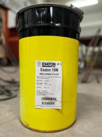
Fig.9 EXATON 15W
TABLE 3
COMPOSITION OF EXATON 15W
|
C% |
Mn% |
Si% |
Ni% |
Cr% |
Mo% |
V% |
Co% |
W% |
Fe% |
|
0.01 |
0.4 |
0.20 |
Bal |
15.1 |
15.6 |
0.1 |
0.1 |
3.6 |
6.8 |
F. Composition of the Material
1) Base Metal: Mild Steel AISI 1020
TABLE 4
COMPOSITION OF BASE METAL
|
C% |
Si% |
Mn% |
P% |
S% |
Cr% |
Ni% |
Mo% |
Cu% |
Al% |
Ti% |
|
0.141 |
0.246 |
0.820 |
0.008 |
0.025 |
0.075 |
0.083 |
0.019 |
0.269 |
0.003 |
0.001 |
2) Electrode: Low Carbon Copper Coated
TABLE 5
COMPOSITION OF ELECTRODE
|
C% |
Si% |
Mn% |
P% |
S% |
Cr% |
Mo% |
Ni% |
Al% |
Cu% |
Nb% |
|
0.1311 |
0.2422 |
2.4763 |
0.0259 |
0.0480 |
0.1088 |
<0.001 |
0.0925 |
0.0099 |
0.1061 |
0.0166 |
|
Ti% |
V% |
W% |
Sn% |
Co% |
B% |
Bi% |
N% |
Ca% |
Pb% |
Ce% |
|
<0.0003 |
0.0032 |
<0.0003 |
0.0266 |
0.0395 |
<0.0003 |
<0.001 |
0.0297 |
0.0003 |
0.0090 |
<0.003 |
|
La% |
Mg% |
Zn% |
Zr% |
Fe% |
Te% |
As% |
Sb% |
Ta% |
|
|
|
<0.0005 |
0.0014 |
0.0075 |
0.0012 |
96.561 |
0.0042 |
0.0140 |
<0.001 |
0.0370 |
|
|
G. Testing
Hardness is a material's resistance to penetration, encompassing wear, scratching, and deformation. Various methods, like Moh's scale and Vickers hardness, measure it. Typically, indentation depth from a specific force and time determines hardness. Brinell hardness involves pressing a steel ball into a specimen, while Vickers hardness uses a diamond pyramid.Rockwell Hardness test consists of indenting the test material with a diamond cone or hardened steel ball indenter. The standard for this test is ASTM E18.The ASTM standards for hardness test are Brinell (ASTM E10), Knoop (ASTM E92, ASTM E384) and Vickers (ASTM E92, ASTM E384).[6]
Strength refers to a material's capacity to withstand external forces without yielding or breaking. Ultimate strength (D) is the maximum stress a material can endure before failure. The stress-strain curve from a tensile test reveals a material's ductility and yield strength, with elastic behaviour up to its elastic limit and plasticity beyond. Beyond the ultimate stress point (D), necking occurs. Strain hardening occurs between yield points and ultimate tensile strength. Young's modulus is obtained from the stress-strain curve within the elastic limit. Strength encompasses a material's ability to withstand loads without failure or distortion. Tenacity denotes a material's resistance to rupture under tensile force.[22]
Toughness refers to a material's ability to withstand bending without fracturing under high impact loads, with mild steel absorbing more energy before failure than glass. Notch toughness measures a metal's resistance to brittle fracture in the presence of flaws or notches under fast loading conditions. Impact tests, such as the Izod and Charpy tests, assess material toughness, with factors like ductility, yield strength, notch, temperature, and fracture mechanism influencing results. In the Charpy test, a V-shaped notch specimen is struck by a hammer to measure fracture energy, while in the Izod test, a similar specimen is struck vertically from the same side as the notch. Standards like ASTM D6110, ASTM E23, and ASTM D256 guide these tests.[24]
The bending test assesses the ductility, bendability, and fracture resistance of mild steel plates under bending forces, aiding in determining their suitability for applications requiring forming and bending. ASTM A370 provides guidelines for conducting such tests, specifying dimensions and procedures for simple or guided bend tests. Results are evaluated based on appearance, cracking, and deformation, ensuring consistent assessment of mechanical properties. Other standards may also be referenced based on application requirements, ensuring reliable evaluation of mild steel plate properties.[3]
IV. RESULT & DISCUSSION
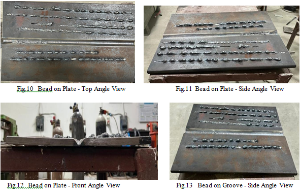
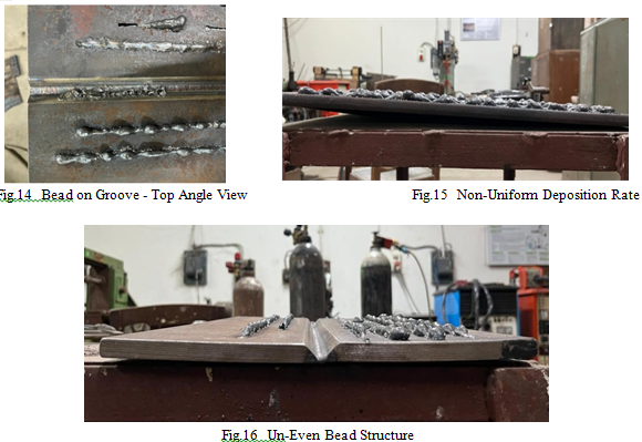
During our project on Submerged Arc Welding (SAW), we encountered various obstacles related to welding parameters and equipment limitations. Initially, our power source was limited to a minimum of 750 amps, with voltage set at a constant 25 volts. While this setup provided high welding current, it also posed issues during the welding process. At the 750-amp current level, we noticed an uneven bead formation, accompanied by inconsistent electrode deposition rates. To address these issues, we attempted to increase the welding current. However, this adjustment introduced new challenges. Raising the welding current required maintaining a high trolley speed to prevent electrode sticking and ensure uniform flux deposition from the hopper. Despite our efforts, we faced additional complications. A significant increase in current led to heightened heating efficiency, resulting in spattering and excessive penetration. These issues adversely affected the overall quality and efficiency of the welding process, prompting us to reassess our approach and find effective solutions.
Conclusion
Preparing the edges of the plate in V-groove shape to provide a surface for proper deposition. Also backing up the plate by supporting with TIG rooting which strengthens weld joints.Flux must be free from oxides to prevent defects. Any presence of moisture will also contaminate the flux quality and slag inclusion can occur.Optimal range for SAW parameters for various variables are; current (450-550 amps) and voltage (22-33 volts).Trolley travel speed was from 670-780 mm/sec which was seen to be fast, therefore non uniform deposition rate has been observed.
References
[1] M.P.Siva, K.Raja, P.L.Rupesh “Effect of Welding Parameters Controlling Submerged Arc Welding Process,” Internal Journal of ChemTech Research, vol. 10, 2017. [2] Raju Pant, Bishal Bhandari, “Thermo-Mechanical Based Residual Stress and Distortion Visualization Using Analytical, Graphical, and FEM Based Numerical Methods,” 2021. [3] R. P. Singh, Aman Singh, “A review of effect of welding parameters on the mechanical properties of weld in submerged arc welding process,” 2020. [4] Pankaj Sharma, Rahul Chahal, “A REVIEW ON SUBMERGED ARC WELDING,” International Research Journal of Engineering and Technology, vol. 9, no. 4, 2022. [5] Suck-Joo Na, Degala Ventaka Kiran, “Experimental Studies on Submerged Arc Welding Process,” Journal of Welding and Joining (vol. 32, No. 3), 2014. [6] Bolem VK Susmitha, Jeeri Chaitanya, Enukoti Venkatesh, Gorle Harikanth, “Effect Of Submerged Arc Welding On Weldability And Mechanical Properties Of Is2062,” Department Of Mechanical Engineering Anil Neerukonda Institute Of Technology & Sciences, 2018. [7] G. D. Uttrachi, “Multiple electrode systems for submerged arc welding,” Welding Journal, 1978. [8] P.V. Gopal Krishna, K. Kishor, Kota Manish Kumar, “Study of Metallurgical and Mechanical Properties in Submerged Arc Welding With Different Composition of Fluxes-A Review,” Materials Today: Proceedings vol 22, 2020. [9] Dheerendra Dwivedi, Keshav Prasad, “Some investigations on microstructure and mechanical properties of submerged arc welded HSLA steel joints,” International Journal of Advanced Manufacturing Technology, March 2008. [10] H. P Seow, F.L Cheong, R.S Chandel, “Effect of increasing deposition rate on the bead geometry of submerged arc welds,” Journal of Materials Processing Technology (vol. 72, no. 1), 1997. [11] V.V. Patel, P.B. Patel, Gautam Vinzoda, “Parametric Investigation of Submerged Arc Welding on Mild Steel IS-2062,” Journal of Emerging Technologies and Innovative Research (JETIR), (vol. 6, no. 4), 2019. [12] P. Bharathipriya , “A Literature Review on Submerged Arc Welding (SAW),” International Journal of Innovative Research in Technology, (vol. 9, no. 7), 2022. [13] “Minimizing Weld Defects in SAW.” Nalla Gane. [14] Abed Fares Ali, “Defects, types and classification of the advance welding process-based industry: A review,” Journal of Mechanical Engineering Research and Developments, 2021. [15] https://images.app.goo.gl/MYpAWWkCovREug1k8. [16] Chandrakesh Singh, Ashu Kumar Verma, Rudra Pratap Singh, “Effect of quenching and annealing on the hardness of submerged arc welded mild steel plates,”Materials Today: Proceedings (vol 26, no 2), 2020. [17] Harish Kumar Arya, Ravindra K Saxena, Rahul, “Effect of Cooling Rate on Microstructure of Saw Welded Mild Steel Plate (Grade C 25 as Per IS 1570),” International Journal of Modern Engineering Research (vol. 4, no. 1), 2014. [18] Abhijit Bhowmik, Ajay Biswas, Saurav Datta, Swapan Bhaumik, “Feasibility Study of Submerged Arc Welding (SAW) on Mild Steel Plate IS 2062 Grade B at Zero Degree Celsius” in Singapore SG Mar 29-30, 2015. [19] James Amanie, “Effect of submerged arc welding parameters on the microstructure of SA516 and A709 steel weld,” University of Saskatchewan Saskatoon, 2011. [20] Shahaji Dhende, Shruti Banait, Bhagwan F. Jogi, W. Tanveer Tadavi, Pranita Wagh, “Microscopic Analysis of Heat Affected Zone (HAZ) of Submerged Arc Welding (SAW) Joint for 1018 Mild Steel Sheet,” Advances in Intelligent System Research, vol. 137, 2017. [21] Rajkumar.T, Navaneetha Krishnan.S, Nirmal Kumar.B, Shiek Samsudeen.M, Siva Kumar.k, “Submerged Arc Welding Process for Mild Steel - Review,” International Journal for Science and Advance Research in Technology, vol. 6, no. 1, 2020. [22] Neha Mainwal, Manwi Khandelwal, Prateek Sunil Jadhav, Saurabh Dewangan, “Performance analysis of heat treated AISI 1020 steel samples on the basis of various destructive mechanical testing and microstructural behaviour,” Australian Journal of Mechanical Engineering, 2019. [23] https://esab.com/mv/ind_en/products-solutions/product/filler-metals/stainless-steel/subarc-saw/exaton-15w/. [24] S.Senthil Murugan, “Mechanical Properties of Materials: Definition, Testing and Application,” International Journal of Modern Studies in Mechanical Engineering, (vol. 6, no. 2), 2020.
Copyright
Copyright © 2024 Hemant Panchal, Ishan Yadav, Harshil Variya, Prakashchandra Tiwari, Yash Tandel. This is an open access article distributed under the Creative Commons Attribution License, which permits unrestricted use, distribution, and reproduction in any medium, provided the original work is properly cited.

Download Paper
Paper Id : IJRASET64851
Publish Date : 2024-10-27
ISSN : 2321-9653
Publisher Name : IJRASET
DOI Link : Click Here
 Submit Paper Online

