Ijraset Journal For Research in Applied Science and Engineering Technology
- Home / Ijraset
- On This Page
- Introduction
- Conclusion
- References
- Copyright
Evaluation Performance of Seven Level Symmetrical and Asymmetrical Inverters
Authors: Devsoth Srinivas, T Murali Krishna, Akash Gangula, P Pradeep Kiran
DOI Link: https://doi.org/10.22214/ijraset.2024.63774
Certificate: View Certificate
Abstract
Introduction
I. INTRODUCTION
In industrial drive applications, conventional two-level inverters are becoming less and less useful because of their shortcomings, which include the necessity for more switching elements, extra switching losses, large driver circuit requirements, and high dv/dt issues. Differently topological multi-level inverters have been developed to tackle these issues. The diode-clamped, flying capacitor, and cascaded H-bridge topologies are examples of traditional topologies. Diode-clamped and cascaded H-bridge topologies are two of these that have become more popular in different applications. [1-2]The diode-clamped architecture connects capacitors in series to produce varying voltage levels with just one DC source needed. It does, however, have a voltage balancing issue. The cascaded topology, on the other hand, simplifies the design because it needs several DC sources. Voltage balancing and control circuit complexity are two issues with the flying capacitor topology. After experimenting with different configurations of these fundamental topologies, cascaded H-Bridge topologies emerged as a possible remedy[3-5]. It takes three voltage sources of identical magnitude and twelve switching devices per phase to operate a symmetrical seven-level multi-level inverter. While a symmetrical MLI requires eight switches and two voltage sources of different values for the same output, an asymmetrical seven-level MLI requires just two, meaning that it is more efficient[6-10].
II. STRUCTURE OF SYMMETRICAL SEVEN LEVEL CASCADED ML INVERTER
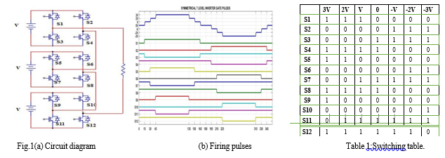
Three bridges (h1, h2, and h3) cascaded in series make up the circuit diagram of the seven-level inverter depicted in Fig. 1. It also has twelve switches. Any bridge has the capacity to produce voltage V. When two bridges are operated, 2V is produced; when three bridges are run, 3V is produced; and the sum of their respective negative values results in seven levels of voltage. An advanced inverter that produces high-quality AC voltage waveforms with seven unique voltage levels is a symmetrical seven-level multi-level inverter. The symmetric distribution of these levels around zero leads to the accurate and balanced creation of waveforms. This kind of inverter greatly reduces harmonic distortion by simulating a sinusoidal waveform with several DC voltage sources or capacitors and suitable switching mechanisms. Benefits include superior power output quality, enhanced power transmission efficiency, less strain on linked devices, and enhanced power system performance overall, which makes it perfect for grid-connected power production, renewable energy systems, and motor drives. These inverters, however, are more complicated and call for higher performance switching devices, sophisticated control schemes, and additional components. In conclusion, a symmetrical seven-level multi-level inverter is an effective solution for applications requiring high-quality power conversion and transmission since it reduces harmonic distortion and improves power quality. Power semiconductor devices and other components are arranged in a certain way to provide the seven voltage levels that are needed in the output waveform while building a symmetrical seven-level multi-level inverter. This inverter is constructed using a symmetrical cascaded H-bridge topology by joining three single full bridge inverters in series. Three equal-amplitude voltage sources are needed for each bridge, which is made up of four switches (IGBTs in this example) with anti-parallel diodes.
Twelve switches in total and three voltage sources are needed for this design. It is a more traditional technique, but it is simpler than other topologies because it does not require clamping diodes or capacitors. To guarantee the inverter generates high-quality and efficient waveforms for applications such as motor drives and renewable energy systems, meticulous attention to component selection, circuit layout, and control algorithms is required throughout construction and design. The switching states of proposed inverter are as given in the Table 1 above. In the table, 1 indicates the switch is in ON state and 0 shows the switch is in OFF state.
For the voltage level 3V the switches S1, S4, S5, S8, S9 and S12are in ON state and switches S2, S3, S6, S7, S10 and S11 are in OFF state. For the voltage level 2V the switches S1, S4, S5, S8, S11 and S12are in ON state and switches S2, S3, S6, S7, S9 and S10 are in OFF state. For the voltage level V, the switches S1, S4, S7, S8, S11and S12are in ON state and switches S2, S3, S5, S6, S9 and S10 are in OFF state. For the voltage level 0V the switches S3, S4, S7, S8, S11and S12 are in ON state and switches S1, S2, S5, S6, S9 andS10 are in OFF state. For the voltage level -V the switches S2, S3, S7, S8, S11 and S12 are in ON state and switches S1, S4, S5, S6, S9 and S10 are in OFF state. For the voltage level -2V the switches S2, S3, S6, S7, S11and S12 are in ON state and switches S1, S4, S5, S8, S9 and S10 are in OFF state. For the voltage level -3V the switches S2, S3, S6, S7, S10 and S11 are in ON state and switches S1, S4, S5, S8, S9 and S12 are in OFF state.
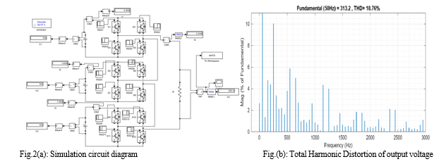
The output voltage and total harmonic distortion (THD) of a symmetrical seven-level multi-level inverter are displayed in the fig 2.The symmetrical seven-level multi-level inverter can produce a waveform that is nearly sinusoidal in shape, as shown in fig.1(b), but there is still a sizable amount of harmonic content (18.76% THD). To ensure that connected loads operate efficiently and to improve power quality, this harmonic distortion needs to be reduced. Improved component selection, improved control tactics, and harmonic filtering approaches can help achieve.
III. OPERATION OF ASYMMETRICAL INVERTER
The circuit diagram of seven-level asymmetrical inverter which has eight switches, four in upper bridge and four in lower bridge is depicted in Fig.3. The upper bridge is supplied with voltage Vdc, the lower bridge is supplied with voltage 2Vdc, Vdc and 2Vdc are unequal voltages that is why the name asymmetrical. The two bridges are cascaded to each other, so when the upper bridge is operated Vdc is appeared at load, when lower bridge operates 2Vdc is appeared, Vdc + 2Vdc is appeared when two bridges are operated, zero is appeared when neither of the voltages appeared across load and their respective negative voltages which makes it seven levels.
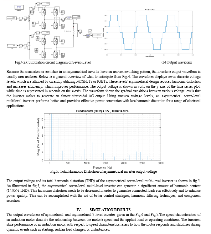
An asymmetrical seven-level multilevel inverter is a power electronic device that converts direct current (DC) into alternating current (AC) at multiple voltage levels. Unlike conventional multilevel inverters with equal voltage levels, asymmetrical inverters use different voltage magnitudes to achieve higher voltage levels with improved efficiency and reduced harmonic distortion.
An asymmetrical seven-level multilevel inverter achieves seven distinct voltage levels using IGBTs or MOSFETs, with unequal voltage magnitudes that enhance performance, leading to better efficiency and reduced harmonic distortion compared to symmetrical inverters. An asymmetrical seven-level multilevel inverter offers enhanced performance by utilizing unequal voltage levels, providing efficient power conversion with reduced harmonic distortion for various electrical applications.
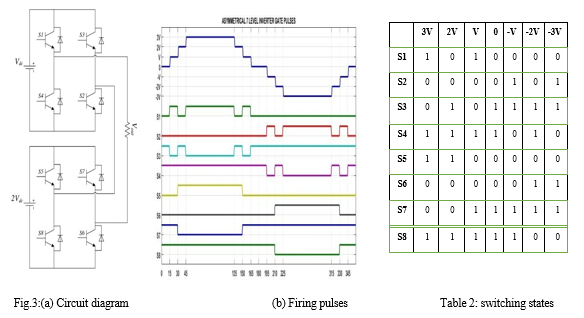
The switching states of proposed inverter are as given in the Table 2 above. In the table, 1 indicates the switch is in ON state and 0 shows the switch is in OFF state. The different modes of operation of 7-level inverter are given below from Fig.3:
- Mode I: Mode I of operation Cascaded H-Bridge model in which the voltage sources of all the two full bridges are on and provides a voltage of 3V at the load. In order to make this happen switches S1, S4, S5, S8, are switched ON.
- Mode II: Mode II of operation Cascaded H-Bridge model in which the voltage sources of only one bridge (lower bridge) is ON and produces a voltage of 2V at the load. In order to achieve this, switches S3, S4, S5, S8, are switched ON.
- Mode III:Mode III of operation Cascaded H-Bridge model in which the voltage sources of only one bridge is ON and provides a voltage of V at the load. To make this happen switches S1, S2, S6, S8, S10 and S12 are switched ON.
- Mode IV:The load voltage will be zero when the switches S3, S4, S7, S8, are conducting. All the sources are disconnected from the load.
- Mode V: When the switches S2, S3, S7, and S8 are turned ON, then the output voltage will become –V.
- Mode VI: The switches S3, S4, S6, and S7 must be turned ON to provide an output voltage of -2V.
- Mode VII: The output voltage -3V is produced by turning ON S2, S3, S6, and S7 where both the bridges operate.
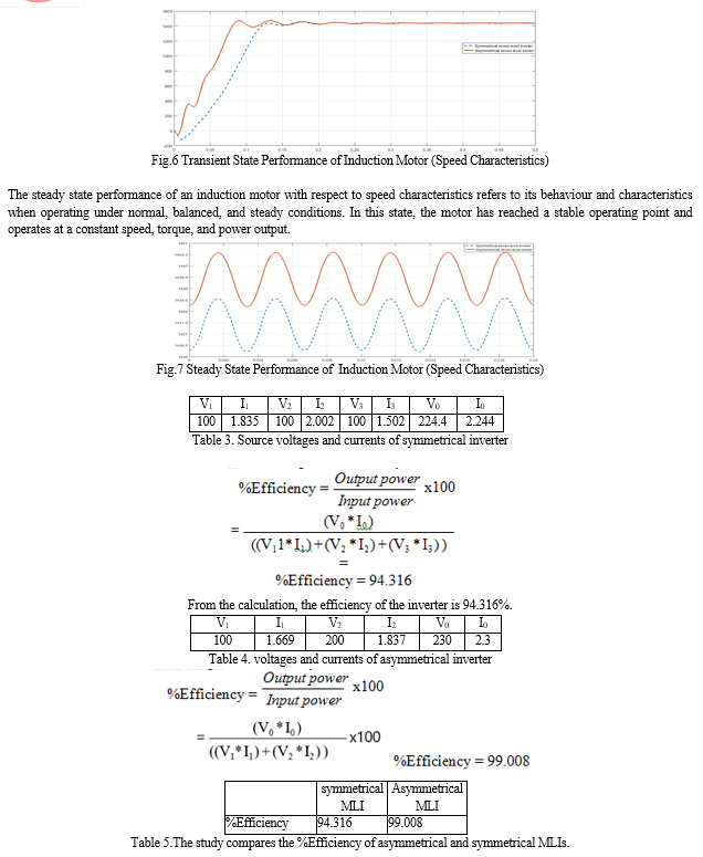
An efficiency of 99.008% is attained by the asymmetric Multi-Level Inverter (MLI), demonstrating excellent power conversion with low losses. On the other hand, the symmetrical MLI has a little lower power conversion effectiveness, as evidenced by its lower efficiency of 94.316%. Despite its superior efficiency, the asymmetrical MLI may result in increased harmonic distortion and necessitate more intricate control techniques. The symmetrical MLI has lower efficiency but provides simpler control and greater waveform quality. Whether one prioritizes improved waveform quality and control simplicity over increased efficiency will determine which option is best.
Conclusion
In this paper, 7-level asymmetrical inverter, asymmetrical inverter with and without PWM are presented and compared based on THD parameters. Simulation results are computed using MATLAB/SIMULINK software. The eight switches are needed to produce the same output when the switches are asymmetrical. As the number of switches is reduced, switching losses also decreased which is why asymmetrical has higher efficiency. Table 5 gives the comparison of efficiency for asymmetrical MLI and symmetrical MLI. With an efficiency of 99.008%, the asymmetric Multi- Level Inverter (MLI) provides excellent power conversion at the cost of sophisticated management and possibly higher harmonic distortion. In contrast, applications that prioritize simplicity of control and waveform purity are a good fit for the symmetrical MLI, which has an efficiency of 94.316% and offers superior waveform quality and simpler control. Analysis of this paper comes to the point that asymmetrical inverter has excelled in the performance parameters showing better results which makes it ideal for various applications. From the fig.6 and 7 gives the information speed characteristics of the induction motor at two states (i) transient state (ii) steady state. For transient state the symmetrical inverter has less overshoot in the output and asymmetrical inverter has more over shoot in the output speed. From the fig.6 & 7 shows the speed characteristics of the induction motor at two main states (i) transient state (ii) steady state. For transient states the motor connected to asymmetrical seven level inverter have damping’s and symmetrical seven level inverter has smooth operation in the transient state. In steady state operation the asymmetrical has less slip for the same load and the symmetrical seven level will operate in low speed.
References
[1] G. Ratnaiah, G. Ramya, ?Comparative analysis of cascaded H bridge multilevel inverter with control topology,? 2022 International Virtual Conference on Power Engineering Computing and Control: Developments in Electric Vehicles and Energy Sector for Sustainable Future (PECCON), August 2022. [2] Nikhil Agrawal, Anshul Agarwal, Tripathiraju Kanumuri, ?Performance analysis of 7 level cascaded H bridge multilevel inverter with symmetrical and asymmetrical configuration?, 2022 IEEE 10th Power India International Conference (PIICON), February 2023. [3] Radha Sree.K, Sivapathi.K, Vardhaman.Y and Dr.R.Seyezhai, ?Asymmetrical cascaded multilevel inverters for electric vehicles?, International Conference On Advances In Engineering, Science And Management (ICAESM -2012), March 30, 31, 2012. [4] Marif Daula Siddique; Asif Mustafa; Adil Sarwar; Saad Mekhilef, Noraisyah Binti Mohamed Shah, Mehdi Seyedamahmousian, Alex Stojcevski, Ben Horan, Koki Ogura, ?Single phase symmetrical and asymmetrical design of multilevel inverter topology with reduced number of switches?, 2018 IEEMA Engineer Infinite Conference (eTechNxT), June 2018. [5] N. K. Kumari, P. Upadhyay and K. Renu, \"Qualitative analysis of diode clamped multi level inverter fed induction motor with phase shifted SPWM,\" 2017 IEEE International Conference on Power, Control, Signals and Instrumentation Engineering (ICPCSI), Chennai, India, 2017, pp. 817-822, doi: 10.1109/ICPCSI.2017.8391827. [6] K. Sivakumar, A. Das, R. Ramchand, C. Patel and K. Gopakumar, \"A simple five-level inverter topology for induction motor drive using conventional two- level inverters and flying capacitor technique,\" 2009 35th Annual Conference of IEEE Industrial Electronics, Porto, Portugal, 2009, pp. 1009-1013, doi: 10.1109/IECON.2009.5414692. [7] P. S. Jamwal, S. Singh and S. Jain, \"Three-Level Inverters for Induction Motor Driven Electric Vehicles,\" 2020 3rd International Conference on Energy, Power and Environment: Towards Clean Energy Technologies, Shillong, Meghalaya, India, 2021, pp. 1-6, doi: 10.1109/ICEPE50861.2021.9404444. [8] K. Sivakumar, \"A five-level inverter topology for four pole induction motor drive using four two-level inverters and two isolated DC sources,\" 2014 IEEE International Conference on Power Electronics, Drives and Energy Systems (PEDES), Mumbai, India, 2014, pp. 1-5, doi: 10.1109/PEDES.2014.7042005. [9] H. Joshi, P. N. Tekwani and A. Hinduja, \"Multi-level inverter for induction motor drives: Implementation using reversing voltage topology,\" 2010 Conference Proceedings IPEC, Singapore, 2010, pp. 181-186, doi: 10.1109/IPECON.2010.5697102. [10] T. M. Krishna and C. B. Kumar, \"A new hybrid Multi Level Inverter to improve the performance of induction motor,\" 2015 International Conference on Computation of Power, Energy, Information and Communication (ICCPEIC), Melmaruvathur, India, 2015, pp. 0264-0268, doi: 10.1109/ICCPEIC.2015.7259473.
Copyright
Copyright © 2024 Devsoth Srinivas, T Murali Krishna, Akash Gangula, P Pradeep Kiran. This is an open access article distributed under the Creative Commons Attribution License, which permits unrestricted use, distribution, and reproduction in any medium, provided the original work is properly cited.

Download Paper
Paper Id : IJRASET63774
Publish Date : 2024-07-26
ISSN : 2321-9653
Publisher Name : IJRASET
DOI Link : Click Here
 Submit Paper Online

