

Ijraset Journal For Research in Applied Science and Engineering Technology
Experimental Assessment on the Performance of Steel-Fiber-Reinforced Concrete
Authors: Pranjul Dubey, Rohit Sahu, Pankaj Singh, Rajesh Singh, Tanmay Singh
DOI Link: https://doi.org/10.22214/ijraset.2024.64317
Certificate: View Certificate
Abstract
In previous years there is lots of research on fibre Reinforced concrete. In this project we make M 60 and replace steel fibre with volume of concrete. In addition, we also replace volume of cement with silica fume, fly ash and rice husk ash. This paper shows various mix design with different ratios of steel fibre, silica fume, fly ash and rice husk ash. We perform compression test, split tensile test and flexural test. The objective of this project was to understand the behaviour of steel fibre reinforced concrete with different additives such as silica fume, fly ash and rice husk ash with different percentage of steel fibre. Compressive strength, split tensile strength and flexural strength was tested on cubes, cylinder and beams. In this project we make 27 cubes,21 cylinder and 14 beams.
Introduction
I. INTRODUCTION
Concrete, as one of the most widely used construction materials, offers considerable strength and durability. However, its inherent brittleness and low tensile strength remain limitations in its application, particularly under dynamic or tensile loads. To overcome these deficiencies, the integration of fibres into concrete has emerged as a viable solution, offering enhanced performance and mechanical properties. Among various fibre types, steel fibres have gained prominence due to their ability to improve concrete’s tensile strength, ductility, and crack resistance.
Steel-fibre-reinforced concrete (SFRC) presents a composite material that combines the properties of conventional concrete with the reinforcing capabilities of steel fibres, leading to improved toughness, impact resistance, and structural integrity. By distributing fibres throughout the concrete matrix, SFRC effectively bridges cracks, reducing crack propagation and improving post-crack behaviour under loading. This results in a more durable and resilient material, suitable for a range of applications such as industrial floors, pavements, and structural elements subjected to high stress.
This study aims to experimentally assess the mechanical behaviour of steel-fibre-reinforced concrete, focusing on parameters such as compressive strength, flexural strength, and crack resistance. By evaluating the performance of SFRC through various laboratory tests, this research seeks to contribute to the growing body of knowledge on fibre-reinforced concretes and provide insights into their potential applications in modern construction practices.
II. LITERATURE REVIEW
The incorporation of fibers into concrete has been an area of extensive research aimed at improving the material's mechanical properties, particularly its tensile strength and toughness. Steel-fiber-reinforced concrete (SFRC) has garnered considerable attention due to its ability to mitigate the brittle nature of conventional concrete by enhancing its ductility and post-cracking performance.
A. Early Developments in Fiber Reinforcement
The use of steel fibres in concrete dates back to the 1960s when researchers like Romualdi and Batson (1963) demonstrated the benefits of adding fibres to improve crack resistance and tensile strength. Since then, numerous studies have explored the various fibre types, shapes, and volume fractions that optimize the mechanical properties of concrete. Banthia and Trottier (1995) provided a comprehensive analysis of the influence of fibre geometry on the post-cracking behaviour of concrete, concluding that hooked-end fibres offer superior crack-bridging capabilities.
B. Mechanical Properties of SFRC
Recent studies have focused on assessing the mechanical performance of SFRC under different conditions. Mohammadi et al. (2008) investigated the effect of steel fibre content on the compressive and flexural strength of concrete. Their findings indicated that with increased fiber volume fraction, significant improvements in both compressive strength and energy absorption capacity were achieved. Further, Kazmi et al. (2018) highlighted the ability of SFRC to enhance the flexural strength and toughness, making it an ideal material for structures exposed to dynamic or cyclic loads.
C. Crack Resistance and Durability
Crack resistance is a critical factor in the durability and longevity of concrete structures. Studies by Yoo et al. (2016) revealed that steel fibers effectively reduce crack width and spacing, which improves the long-term durability of concrete by limiting the ingress of harmful agents such as water and chloride ions. Other research has emphasized the role of fiber distribution and orientation in crack control, with researchers like Ezeldin and Lowe (1991) demonstrating that randomly distributed steel fibers result in more uniform crack resistance across the concrete matrix.
D. SFRC in Practical Applications
The application of SFRC in real-world scenarios has also been explored extensively. Bentur and Mindess (2007) discussed the use of SFRC in industrial floors, pavements, and tunnel linings, citing its enhanced fatigue resistance and reduced maintenance costs. Their work, along with findings from Bhargava et al. (2017), showed that SFRC could outperform conventional concrete in terms of load-bearing capacity and longevity under heavy traffic conditions, making it suitable for infrastructural applications.
E. Limitations and Challenges
Despite its advantages, the application of SFRC is not without challenges. Research by Ochi et al. (2001) pointed out the difficulties in mixing and placing steel fibers uniformly in the concrete matrix, which can lead to issues such as fiber balling and uneven distribution.
Additionally, the cost of steel fibres can increase the overall construction cost, limiting its widespread adoption. However, ongoing studies by researchers like Lok and Pei (1998) suggest that optimizing fibre content and concrete mix design can minimize these challenges while maximizing the material’s benefits.
F. Recent Advances in SFRC
Recent research has explored the hybridization of steel fibres with other types of fibres, such as polypropylene, to further enhance the performance of concrete.
For instance, Sharma and Bansal (2018) demonstrated that hybrid fibre-reinforced concrete could offer superior toughness and strain capacity compared to single-fibre systems, leading to a more resilient and versatile material for modern construction. Furthermore, advanced modelling techniques and experimental setups have been used to better understand the load-bearing mechanisms in SFRC, allowing for more precise design criteria in engineering practice.
III. EXPERIMENT OVERVIEW
For compression test 27 cubes was casted respectively. We also performed split tensile test and 4-point flexure test. We designed the concrete for M60 strength. We construct 21 cylinder of size 20×10cm and 14 beams of size 10×10×50 cm. 27 cubes casted 9 cubes are without fibre and rest are with 2%, 2.5%, 3% fiber. We checked the strength on 14 and 28 days for compressive test.
A. Experiments
1) Compression Test
This test was done in accordance with IS 516-1959.The cubes of standard size 150×150×150mm and 100×100×100mm were used to find the compressive strength of concrete.
Cubes were placed on the bearing surface of compression testing machine, of capacity 200 tones and a uniform rate of loading of 140 Kg/cm2 per minute was applied till the crack appear on the cube. The maximum load was noted and the compressive strength was calculated. The results are tabulated in table 3.1
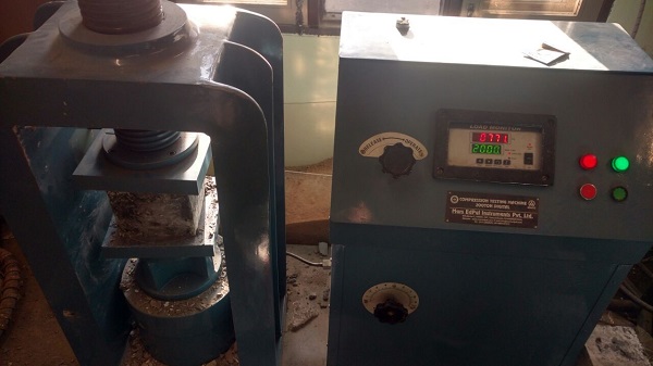
Fig. 3.1 Compression Testing Machine
Procedure
- Prepare the specimen of size 15×15×15cm in size.
- The concrete should be filled in specimen in layer of 5 cm with proper compaction of each layer either vibration machine or hand tamping.
- The mould should be kept at damp condition for 24 hours.
- After that the cube should be put in bath tub at a standard temperature of 27±2 oC.
- The cubes should be tested immediately on removal from water.
- The load should be applied slowly without any shock at a rate of approximately 140Kg/cm2/min.
- The max load applied to the specimen should be noted for each cube.
Calculation
Compressive strength in MPa = P/A Here P = applied load
A = cross sectional area
2) Split Tensile Strength Test
Concrete is brittle in nature and therefore tensile strength plays an important role for structure safety purposes. This test is also performed on CTM machine. In this test we constructed 21 cylinders out of which 3 cylinders are for each 0, 2, 2.5, 3 % steel fibre and 3 each for rice husk ash, fly ash, silica fumes.
Procedure:
- The cylinder of size 20×10 cm size is made.
- Centre line shall be drawn on the two opposite faces of the cube which will ensure that they are in same axial plane.
- The mass and dimension of cylinder should be measured before the testing.
- The rate of loading should be smooth and should not be shock loading.
- The rate of loading should be maintained within the range of 1.2N (mm2/min) to
- 2.4 N (mm2/min).
- Maintain the rate once applied until failure.
- Note the maximum reading.
Calculation
Splitting tensile strength fct =2P/πld
Where P = max load applied in Newton applied l = length of cylinder (mm)
d = cross-section dimension of cylinder (mm)
3) Four Point Flexure Test
The four point bending flexural test provides values for the modulus of elasticity in bending, flexural stress, flexural strain, and the flexural stress-strain response of the material. This test is very similar to the three-point bending flexural test but this method is superior to this because more beam area is exposed to stress.
There are several advantages of four-point bending test over uniaxial tensile test are following:
- Simple geometries of sample
- Sample machining is minimum required
- Simple text fixture
- Possibility to use as-fabricated materials
And disadvantage is that stress distribution is more complex throughout the beam.
B. Materials Used
1) Cement
We use OPC cement and its specific gravity of OPC was 3.14. We use OPC 53 grade cement of ACC.
2) Water
Tape water was used.
3) Steel Fibre
Corrugated Steel Fibres
Corrugated steel fibers from Walia & Company as shown in fig 3.2 were used those length is 35-45 mm and Dia of 0.55-0.73mm having aspect ratio of about 61. The tensile strength of fiber is 1200 N/mm2.
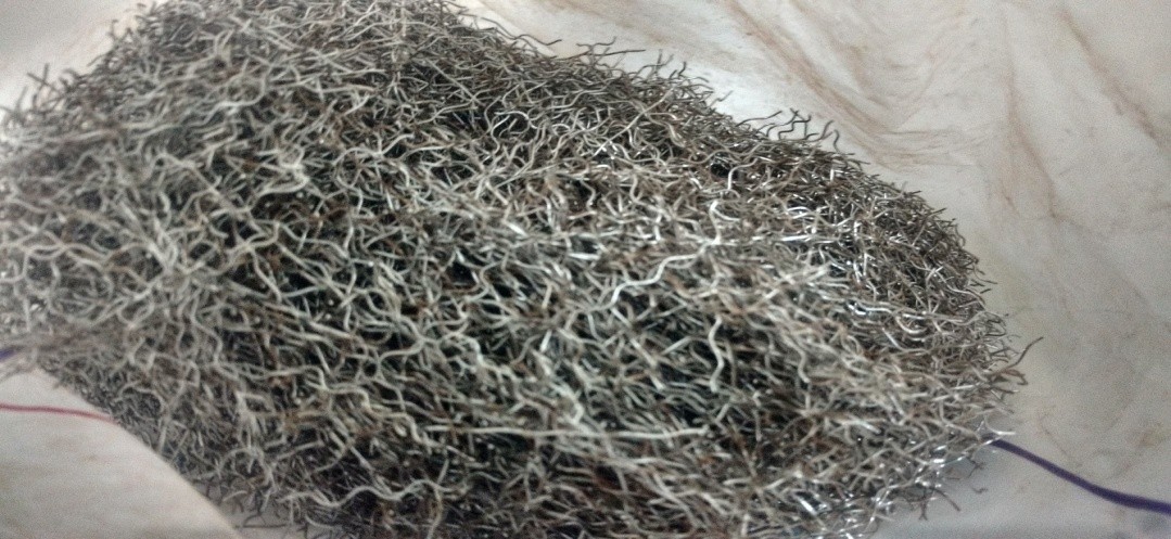 Fig. 3.2 Steel fiber used in project
4) Fine Aggregate
We were using River sand in testing according to IS 2386 (PART I) whose Specific gravity is 2.63.
Absorption of water is -1%.
Zone of fine aggregate is zone IV.
5) Coarse Aggregate
We use Crushed stone aggregates having maximum size 20 mm in our tests as per IS 2386 (part III) of 1963.and specific gravity is 2.57.
Absorption of water is 0.8%.
6) Casting of Mould
The materials were weighed accurately using a digital weighing instrument. For plain concrete, fine aggregates, coarse aggregate, cement, water were added to the mixture machine and mixed thoroughly for three minutes.
Steel fibers were mechanically sprinkled inside the mixture machine after thorough mixing of the ingredients of concrete as shown in fig. 3.3.
The cubes of 15×15 cm was prepared. Before mixing the concrete, the molds were kept ready. The sides and the bottom of the all the mold were properly oiled for easy demolding.
7) Curing
Cubes were at a stable ground and kept at a temperature of 27±2?C for 24 hours as shown in fig. 3.4. After this, the cubes and cylinder were marked and removed from the molds and after that the cubes was submerged in clean fresh water for duration until it was used the testing day. The cubes were allowed to become dry before testing.

Fig. 3.4 Curing of cubes
C. Mix Design of Concrete
We have designed our mix by IS 10262:2009
1) Step 1: Characteristic Strength of concrete
fck’ = fck + 1.65s From IS 456, s= 5 for M60
= 60+1.65×5
= 68.25 MPa
2) Step 2: Selection of water/cement or cementations ratio
Form IS 456,
W/c= 0.24
3) Step 3: Selection of water content
From IS 456, at w/c = 0.50 and angular aggregates having maximum nominal size of 20mm
Suggestive water content = 186 kg/m3
2% super plasticizer by weight of cement is used that result in 30% reduction in water content.
So, Final water content = 186×0.30
= 130.2 kg/m3
4) Step 4: Selection of cement content
Cement content = water content/water to cement ratio
=130.2/0.22
=591.82kg/m3
5) Step 5: Estimation of Coarse Aggregate Proportion in Total Aggregate
For w/c=0.50 and zone IV and max nominal size of aggregate=20mm
Coarse aggregate proportion in total aggregate= 0.66
Since there is a decrease in the w/c ratio (0.50-0.22=0.28) this proportion is increased according to the code recommendation by (0.28/0.05=5.6%)
Corrected coarse aggregate proportion in total aggregate= 0.66+5.6/100 = 0.72
Fine aggregate proportion in total aggregate = 1-0.72 = 0.28
6) Step 6: Mix design calculations
-
-
- Volume of concrete = 1m3
- Volume of cement = (Mass /Specific gravity) ×(1/1000)
-
= (591.82/3.15) × (1/1000)
= 0.187m3
-
-
- Volume of water = (Mass /Specific gravity ) ×(1/1000)
-
= (130/1) × (1/1000)
= 0.130 m3
-
-
- Volume of super plasticizer = (Mass of super plasticizer/Specific gravity
-
of water) × (1/1000)
= (2×591.8/1.1×100) ×(1/1000)
=10-2 m3
-
-
- Volume of all in aggregate = 1-(b+ c + d)
-
= 1-(0.187+0.130+10-2)
= 0.673 m3
-
-
- Mass of coarse aggregate = (e)×(CA)×(specific gravity of coarse aggregate)×(1000)
-
= 0.673 ×0.72 ×2.57 ×1000
= 1245.31 kg/m3
-
-
- Mass of fine aggregate = e × FA × specific gravity of fine aggregate ×1000
-
= 0.67 ×0.5 ×2.63 × 1000
= 495.5kg/m3
D. Final Result
Cement = 591.82 kg/m3 Water = 130.2 kg/m3
Fine aggregate = 495 kg/m3 Coarse aggregate =1245.31 kg/m3 Super plasticizer =11.83kg/m3
E. Final Ratio
C: W: FA: CA: SP = 1:0.22:0.83:2.1:0.02
TABLE 3.1 MIX DESIGN FOR STEEL FIBRE
|
% Replacement |
Concrete content(kg/m3) |
Steel fiber(kg/m3) |
|
0 |
C: 591; W: 130; F: 495; CA: 1245 |
0 |
|
2 |
C: 579; W:127; F: 485.1; CA: 1220.1 |
156 |
|
2.5 |
C: 576; W:126.7; F: 482.6; CA: 1214 |
195 |
|
3 |
C: 573; W: 126; F: 480; CA: 1208 |
234 |
Table 3.1 shows the ratio of concrete design at different percentage of steel fibre.
TABLE 3.2 MIX DESIGN FOR STEEL FIBRE PER (15×15×15) cm3 CUBE
|
%Replacement |
Concrete content per cube (grams) |
Steel fiber per cube (grams) |
|
0 |
C: 133; W: 29.3; F: 111.4; CA: 280 |
0 |
|
2 |
C: 130; W: 28.575; F: 109; CA: 275 |
35.1 |
|
2.5 |
C: 129.6; W: 28.5; F: 109; CA: 273 |
43.9 |
|
3 |
C: 129; W: 28.35; F: 108; CA: 272 |
52.6 |
Table 3.2 shows the number of constituents of concrete design at different percentage of steel fiber for cube of 15cm×15cm×15cm.
TABLE 3.3 MIX DESIGN FOR SILICA FUME AND STEEL FIBRE
|
%Replacement of silica fume and steel fiber |
Concrete content(kg/m3) |
Steel fiber(kg/m3) |
|
Silica: 0; steel: 0 |
C: 591; W: 130; F: 495; CA: 1245; silica: 0 |
0 |
|
Silica: 15; steel: 0 |
C: 503; W: 130; F: 495; CA: 1245; silica: 62 |
0 |
|
Silica:15; steel: 2 |
C: 492; W: 127.4; F: 485; CA: 1220; silica: 60.7 |
156 |
Table 3.3 shows the ratio of concrete design at different percentage of steel fiber and silica fume.
TABLE 3.4 MIX DESIGN FOR SILICA FUME AND STEEL FIBRE PER (10×10×10) cm3 CUBE
|
%Replacement of silica fume and steel fiber |
Concrete content per cube (grams) |
Steel fiber per cube (grams) |
|
Silica: 0; steel: 0 |
C: 59.1; W: 13.0; F: 49.5; CA: 124.5; silica: 0 |
0 |
|
Silica: 15; steel: 0 |
C: 50.3; W: 13; F: 49.5; CA: 124.5; silica: 6.2 |
0 |
|
Silica: 15; steel: 2 |
C: 49.2; W: 12.7; F: 48.5; CA: 122; silica: 6 |
15.6 |
Table 3.4 shows the number of constituents of concrete design at different percentage of steel fiber and silica fume for cube of 10cm×10cm×10cm.
TABLE 3.5 MIX DESIGN FOR FLY ASH AND STEEL FIBRE
|
%Replacement of fly ash and steel fiber |
Concrete content(kg/m3) |
Steel fiber(kg/m3) |
|
Fly ash: 0; steel: 0 |
C: 591; W: 130; F: 495; CA: 1245; fly ash: 0 |
0 |
|
Fly ash: 10; steel: 0 |
C: 532; W: 130; F: 495; CA: 1245; fly ash: 48.8 |
0 |
|
Fly ash: 10; steel: 2 |
C: 521; W: 127.4; F: 485; CA: 1220; fly ash:47.8 |
156 |
Table 3.5 shows the ratio of concrete design at different percentage of steel fiber and fly ash.
TABLE 3.6 MIX DESIGN FOR FLY ASH AND STEEL FIBRE PER (10x10x10) cm3 CUBE
|
%Replacement of fly ash and steel fiber |
Concrete content per cube(grams) |
Steel fiber per cube (grams) |
|
Fly ash: 0; steel: 0 |
C: 59.1; W: 13.0; F: 49.5; CA: 124.5; fly ash: 0 |
0 |
|
Fly ash: 10; steel: 0 |
C: 53.2; W: 13; F: 49.5; CA: 124.5; fly ash: 4.9 |
0 |
|
Fly ash:10; steel:2 |
C: 52.1; W: 12.7; F: 48.5; CA: 122; fly ash:4.8 |
15.6 |
Table 3.6 shows the number of constituents of concrete design at different percentage of steel fiber and fly ash for cube of 10cm×10cm×10cm.
TABLE 3.7 MIX DESIGN FOR RICE HUSK ASH AND STEEL FIBRE
|
%Replacement of fly ash and steel fiber |
Concrete content(kg/m3) |
Steel fiber(kg/m3) |
|
RHA: 0; steel: 0 |
C: 591; W: 130; F: 495; CA: 1245; fly ash: 0 |
0 |
|
RHA: 10; steel: 0 |
C: 532; W: 130; F: 495; CA: 1245; fly ash: 43.2 |
0 |
|
RHA:10; steel:2 |
C: 521; W: 127.4; F: 485; CA: 1220; fly ash:42.14 |
156 |
Table 3.7 shows the ratio of concrete design at different percentage of steel fiber and rice husk ash.
TABLE 3.8 MIX DESIGN FOR RICE HUSK ASH AND STEEL FIBRE PER (10X10X10) cm3 CUBE
|
%Replacement of fly ash and steel fiber |
Concrete content per cube (grams) |
Steel fiber per cube(grams) |
|
RHA: 0; steel: 0 |
C: 59.1; W: 13; F: 49.5; CA: 124.5; fly ash: 0 |
0 |
|
RHA: 10; steel: 0 |
C: 53.2; W: 13; F: 49.5; CA: 124.5; fly ash: 4.3 |
0 |
|
RHA:10; steel:2 |
C: 52.1; W: 12.7; F: 48.5; CA: 122; fly ash:4.2 |
15.6 |
Table 3.8 shows the amount of constituents of concrete design at different percentage of steel fiber and rice husk ash for cube of 10cm ×10cm × 10cm.
IV. RESULTS AND DISCUSSIONS
A. Compressive Strength
Compressive strength of concrete= P/A Here,
P= Load applied at the time of failure A= Area of cross section
Compressive strength of concrete= 1202 kN/225cm2
=1202×103 /225 × 100
= 53.4 N/mm2
Table 4.1 Compressive Strength
|
Type of Specimen |
Compressive Strength. N/mm2 |
|||
|
14 days |
28 days |
|||
|
OPC |
55.1 |
55.5 |
62.2 |
64.2 |
|
55.5 |
64.8 |
|||
|
56 |
65.8 |
|||
|
HSFRC (3%) |
57.2 |
57.9 |
63.7 |
65 |
|
58.1 |
65.2 |
|||
|
58.4 |
66.1 |
|||
|
HSFRC (2.5%) |
56.6 |
56.1 |
61.1 |
63.8 |
|
55.7 |
63.9 |
|||
|
56.1 |
66.5 |
|||
|
HSFRC (2%) |
52.1 |
54.9 |
62.7 |
64.23 |
|
55.7 |
65.6 |
|||
|
57.1 |
64.4 |
|||
The result in table 4.1 shows that when we add steel fiber there is marginally increased in compressive strength with variation around 1% to -1% at 28 days.
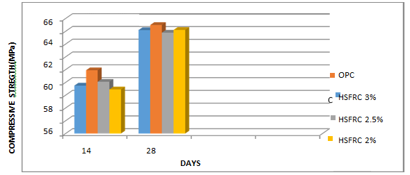
Fig. 4.1 Bar chart for compression testing machine
In this fig. 4.1 we can see that cube having 3% replacement show maximum compressive strength in comparison to another cube. This increase in strength is due to the fact that addition of steel fiber reduces the brittleness of concrete. Cubes for compression testing machine are shown in fig. 4.2 and fig. 4.3 shows the failure pattern of cube after testing.
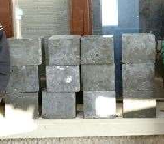
Fig. 4.2 Cubes for CTM testing
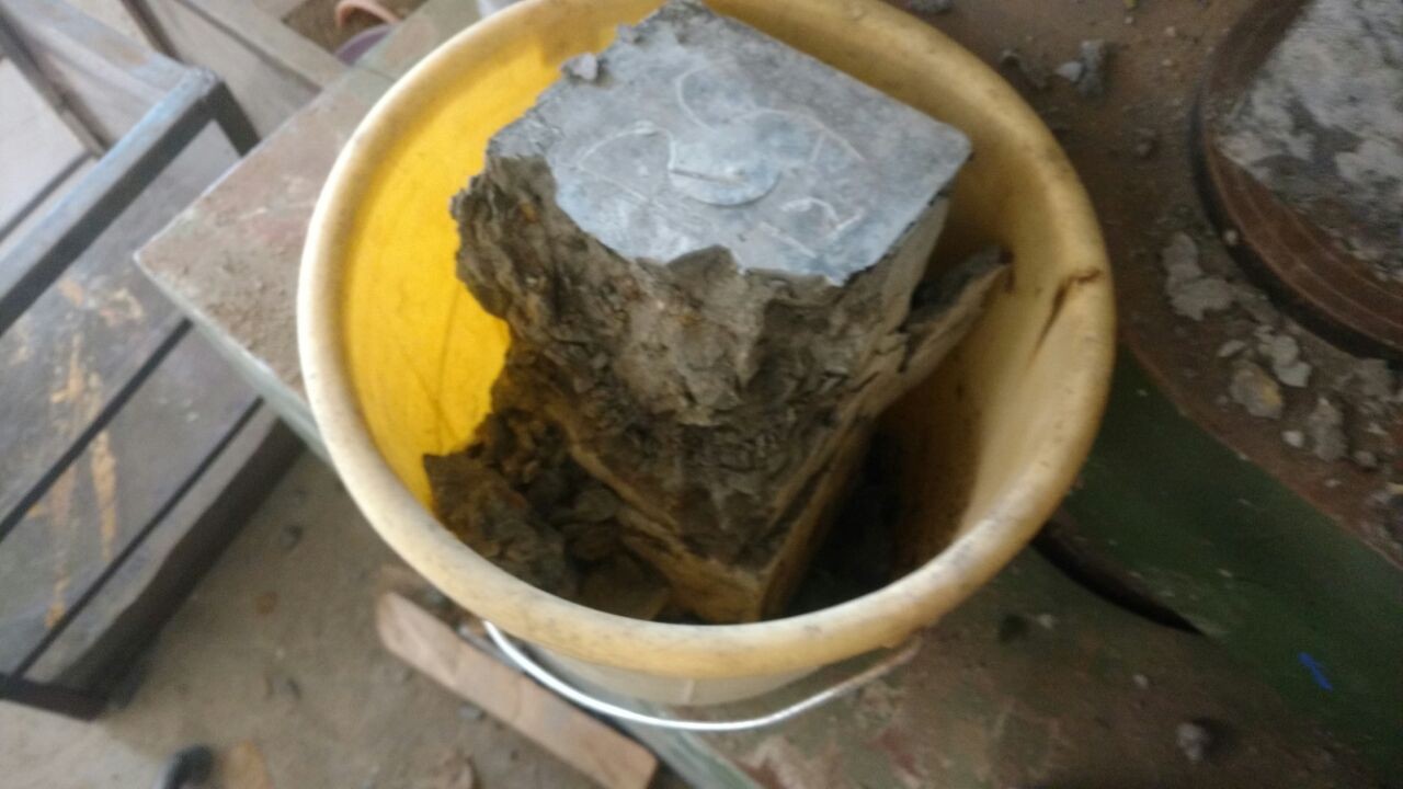 Fig. 4.3 Crack pattern
Table 4.2 Compressive Strength For Silica Fume And Steel Fibre
|
Type of Specimen |
Compressive Strength. N/mm2 |
|||
|
14 days |
28 days |
|||
|
SILICA FUME (15%) |
58.5 |
58.03 |
66.5 |
65.56 |
|
57.9 |
64.9 |
|||
|
57.7 |
65.3 |
|||
|
SILICA FUME (15%) + 2% SFRC |
57.2 |
57.73 |
66.5 |
66 |
|
57.8 |
65.9 |
|||
|
58.2 |
65.7 |
|||
Fig. 4.4 and table 4.2 shows that on replacing OPC with 15% of silica fume than there is increase in compressive strength by comparing it with OPC. After that we replace 2% steel fiber in same concrete mix of silica fume then its compression strength increases.
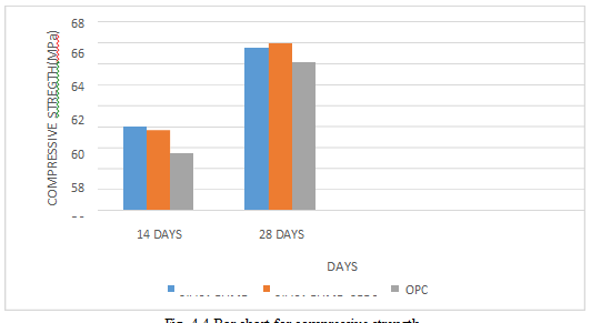
Fig. 4.4 Bar chart for compressive strength
Table 4.3 Compressive Strength Of Fly Ash And Steel Fibre
|
Type of Specimen |
Compressive Strength. N/mm2 |
|||
|
14 days |
28 days |
|||
|
FLY ASH (10%) |
53.4 |
53.8 |
63.5 |
63.23 |
|
54.1 |
62.5 |
|||
|
53.9 |
63.7 |
|||
|
FLY ASH (10%) + 2% SFRC |
54.4 |
53.73 |
64.5 |
65 |
|
53.1 |
65.6 |
|||
|
53.7 |
64.9 |
|||
Fig. 4.5 and table 4.3 show that on replacing OPC with 10% of fly ash than there is increase in compressive strength by comparing it with OPC. After that we replace 2% steel fiber in same concrete mix of fly ash then its compressive strength increases.
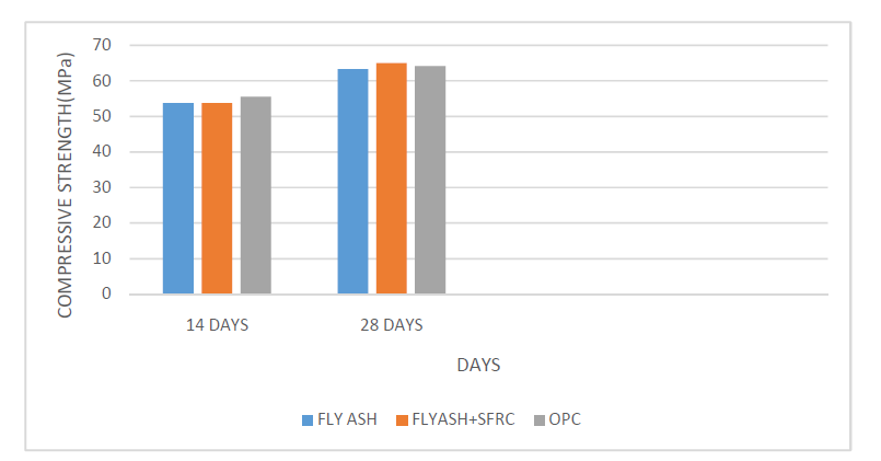
Fig. 4.5 Bar chart for compressive strength
Table 4.4 Compressive Strength Of Rice Husk And Steel Fibre
|
Type of Specimen |
Compressive Strength. N/mm2 |
|||
|
14 days |
28 days |
|||
|
RICE HUSK ASH (10%) |
55.1 |
55.75 |
64.7 |
64.4 |
|
56.2 |
63.5 |
|||
|
55.9 |
65 |
|||
|
RICE HUSK ASH (10%) + 2% SFRC |
54.9 |
55.2 |
64.2 |
65.13 |
|
55.5 |
65.7 |
|||
|
55.2 |
65.5 |
|||
Fig. 4.6 and table 4.4 shows that on replacing OPC with 10% of rice husk ash than there is increase in compressive strength by comparing it with OPC. After that we add 2% steel fiber in same concrete mix of rice husk ash than its compressive strength increases.
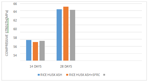
Fig. 4.6 Bar chart for compressive strength
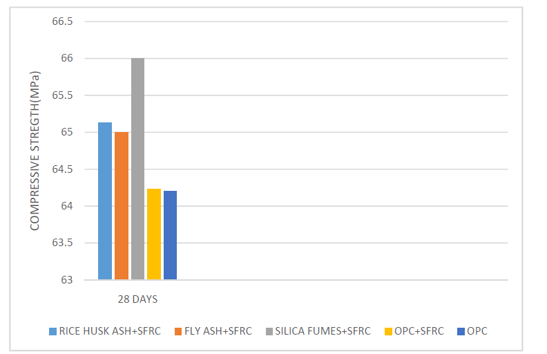
Fig. 4.7 Bar chart for compressive strength
Fig. 4.7 clearly shows that silica fume at 15% replacement show a greater compressive strength than any other additive with SFRC.
B. Split tensile strength
Spilt tensile strength = 2P/πld
Here P = Load applied at the time of failure l = length of cylinder.
D = diameter of cylinder
Spilt tensile strength = 2× 147.65
π × 20×10 = 4.7 N/mm2
Table 4.5 Split Tensile Strength Of Steel Fibre
|
Type of Specimen |
Split Tensile Strength. N/mm2 |
|
|
28 days |
||
|
OPC |
4.7 |
5 |
|
5 |
||
|
5.3 |
||
|
OPC + 2% SFRC |
11.5 |
11.6 |
|
10.9 |
||
|
12.5 |
||
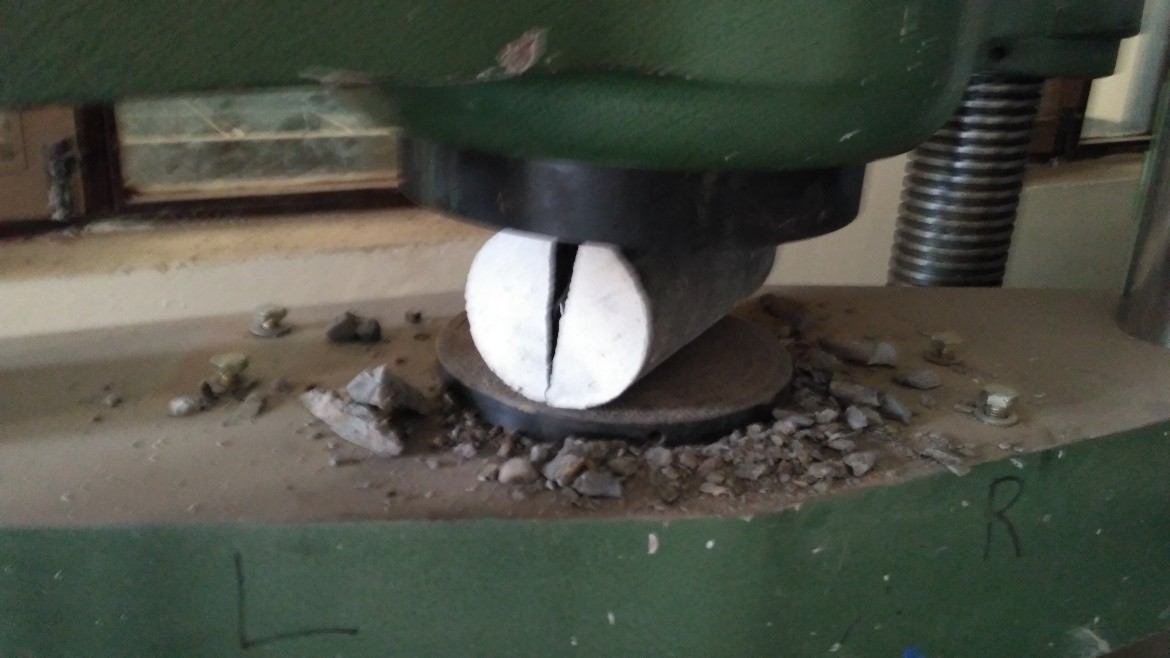
Fig. 4.9 Brittle failure of cylinder without fibre
Fig. 4.10 and table 4.5 shows that on replacing of concrete with 2% steel fiber the result show that the split tensile value increases more than double. And in Fig. 4.9 shows that brittle failure of concrete in split tensile test cylinder without steel fiber.
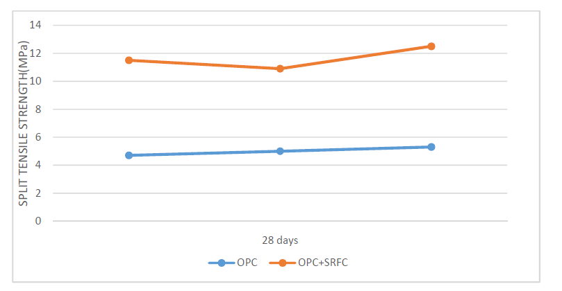
Fig. 4.10 Chart for Variation of Split Strength
Table 4.6 Split Tensile Strength Of Silica Fume And Steel Fibre
|
Type of Specimen |
Split Tensile Strength. N/mm2 |
|
|
28 days |
||
|
SILICA FUME |
6.7 |
7.1 |
|
7.1 |
||
|
7.5 |
||
|
SILICA FUME + 2% SFRC |
14.5 |
14 |
|
15.1 |
||
|
14.2 |
||
Fig. 4.11 and table 4.6 shows that on replacing OPC with 15% of silica fume than there is increase in split tensile strength by comparing it with OPC. After that we replace 2% steel fiber in same concrete mix of silica fume than its split tensile strength increases by double.
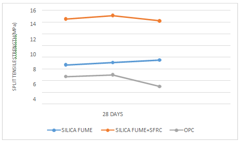
Fig. 4.11 Chart for variation of split strength
Table 4.7 Split Tensile Strength Of Fly Ash And Steel Fibre
|
Type of Specimen |
Split Tensile Strength. N/mm2 |
|
|
28 days |
||
|
FLY ASH |
4.9 |
5.6 |
|
5.7 |
||
|
6.2 |
||
|
FLY ASH + 2% SFRC |
13.2 |
12.76 |
|
12.2 |
||
|
12.9 |
||
Fig. 4.12 and table 4.7 show that on replacing OPC with 10% of fly ash than there is increase in split tensile strength by comparing it with OPC. After that we replace 2% steel fiber in same concrete mix of fly ash than its split tensile strength increases more than double.

Fig. 4.12 Chart for variation of split strength
Table 4.8 Split Tensile Strength Of Rice Husk And Steel Fibre
|
Specimen Type |
Split Tensile Strength. N/mm2 |
|
|
28 days |
||
|
RICE HUSK ASH |
6.5 |
6 |
|
5.4 |
||
|
6.1 |
||
|
RICE HUSK ASH + 2% SFRC |
14.1 |
14.2 |
|
13.6 |
||
|
14.9 |
||
Fig. 4.14 and table 4.8 shows that on replacing OPC with 10% of rice husk ash than there is increase in compressive strength by comparing it with OPC. After that we replace 2% steel fiber in same concrete mix of rice husk ash than its compressive strength increases.
And also fig. 4.13 shows that failure pattern of cylinder with steel fiber.
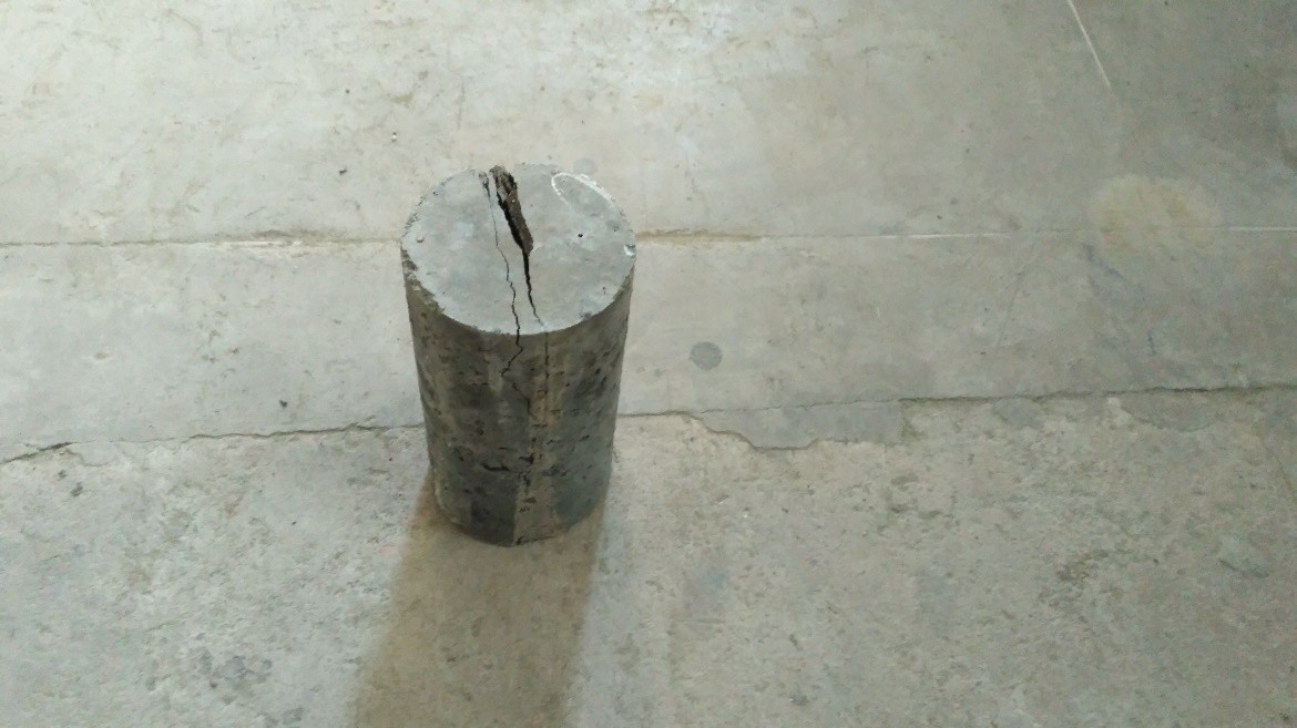
Fig. 4.13 Failure of cylinder with fiber
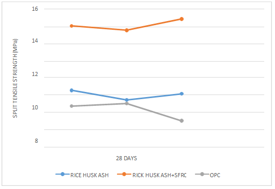
Fig. 4.15 Chart for variation of split strength
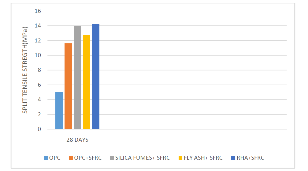 Fig. 4.15 clearly shows that rice husk ash of 10% replacement show a greater split tensile strength than any other additive with SFRC.
C. Flexural Strength
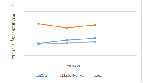
Fig. 4.16 Casting of slab
Table 4.9 Flexural Strength Of Steel Fibre
|
Type of Specimen |
Flexural Strength. N/mm2 |
|
|
28 days |
||
|
OPC |
8.5 |
8.33 |
|
8.7 |
||
|
7.8 |
||
|
OPC + 2% SFRC |
12.5 |
12.6 |
|
11.9 |
||
|
13.4 |
||
Fig. 4.19 and table 4.9 shows that on replacing 2% steel fiber with concrete the result show that the flexural strength value increase more than 50%.
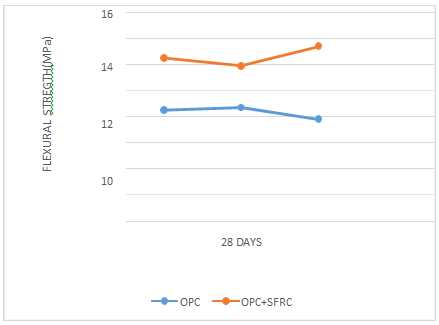
Fig. 4.19 Variation of flexural strength
Table 4.10 Flexural Strength Of Silica Fume And Steel Fibre
|
Specimen Type |
Flexural Strength. N/mm2 |
|
|
28 days |
||
|
SILICA FUME (15%) |
10.5 |
10.5 |
|
11.3 |
||
|
9.7 |
||
|
SILICA FUME (15%) + 2% SFRC |
14.4 |
14.86 |
|
15.3 |
||
|
14.6 |
||
Fig. 4.20 and table 4.10 shows that on replacing OPC with 15% of silica fume than there is increase in flexural strength by comparing it with OPC. After that we replace 2% steel fiber in same concrete mix of silica fume than its flexural strength increases by more than 40%.
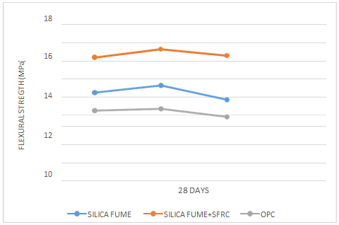
Fig. 4.20 Variation of flexural strength
Table 4.11 Flexural Strength Of Fly Ash And Steel Fibre
|
Type of Specimen |
Flexural Strength. N/mm2 |
|
|
28 days |
||
|
FLY ASH (10%) |
8.5 |
9.16 |
|
9.3 |
||
|
9.7 |
||
|
FLY ASH (10%) + 2% SFRC |
13.5 |
13.9 |
|
14.3 |
||
|
13.9 |
||
Fig. 4.21 and table 4.11 show that on replacing OPC with 10% of fly ash than there is increase in flexural strength by comparing it with OPC. After that we replace 2% steel fiber in same concrete mix of fly ash than its flexural strength increases by more than 40%.
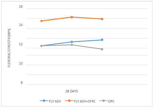
Fig. 4.21 Variation of flexural strength
Table 4.12 Flexural Strength Of Rice Husk And Steel Fibre
|
Type of Specimen |
Flexural Strength. N/mm2 |
|
|
28 days |
||
|
RICE HUSK (10%) |
9.6 |
9.16 |
|
9.7 |
||
|
10.4 |
||
|
RICE HUSK (10%) + 2% SFRC |
14.5 |
15.0 |
|
15.2 |
||
|
15.5 |
||
Fig. 4.22 and table 4.12 shows that on replacing OPC with 10% of rice husk ash than there is increase in flexural strength by comparing it with OPC. After that we replace 2% steel fiber in same concrete mix of rice husk ash than its flexural strength increases by more than 50%.
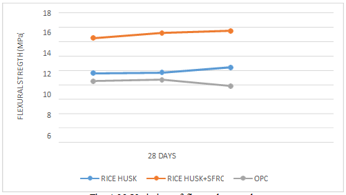
Fig. 4.22 Variation of flexural strength
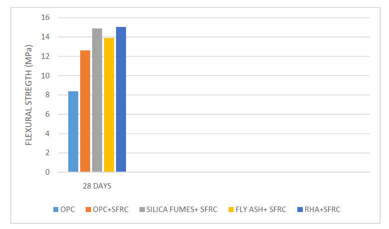
Fig. 4.23 Variation of flexural strength
Fig 4.23 clearly shows that rice husk ash of 10% replacement show a greater flexural strength than any other additive with SFRC
Conclusion
On the basis of experiments, we done in our lab and we conclude different things on the basis of result are as following: 1) The result shows that when we add steel fibre there is marginally increase in compressive strength and split tensile and flexural strength of concrete increase considerably. 2) Maximum compressive strength arrives at 3% fibre replacement. 3) In experiment we use 2%fibre replacement instead of 3% because workability reduces considerably as percentage of fibre increase. 4) Maximum compressive strength is arrived on adding 2% steel fibre and 15% replacement of silica fume whereas compressive strength of 2% steel fibre and 10% Rice husk as his little bit less but it is more eco-friendly and cheaper which is good for builders. 5) Maximum split tensile strength and flexural strength is arrived on adding 2% steel fibre and 10% of rice husk. 6) Addition of rice husk ash is the best additive material that we can add in concrete due to • Greater performance than any other material. • Easy availability. • Eco friendly. • Cheap material as it is a waste material. • Good workability then other.
References
[1] ACI Committee 544 (1984) \"Guide for Specifying, Mixing, Placing, and Finishing Steel Fibre Reinforced Concrete\", American Concrete Institute. [2] ASTM A820-97 (1997) “Standard Specification for steel fibres for reinforced concrete” American society for testing and materials. [3] ASTM C78-97 (1997) “Standard Specification for flexural strength of concrete” (Using simple beam with third point loading) American society for testing and materials. [4] Bargaheiser, K. and Butalia T.S. “Prevention of corrosion in concrete using fly ash concrete mixes”. [5] Bayasi, Z. and Kaiser, H. (2001) \"Steel Fibres as Crack Arrestors in Concrete.\" The Indian Concrete Journal. [6] Chakraborty, S. et al (2015) “A study on the rheological properties of high strength concrete incorporating silica fume” The International Journal of Science and Technology; pp 59-67. [7] Craig, R.et al (1984)\"Behavior of Joints Using Reinforced Fibrous Concrete.\" Fibre Reinforced Concrete International Symposium, SP-81, American Concrete Institute, Detroit,. [8] Dutta, D. et al (2013) “Influence of silica fume on normal concrete” Journal of Engineering Research and Application Vol. 3, Issue 5, pp.79-82 [9] Frank, I. et al (2014) “Blended rice husk ash concrete; a marginal green construction material from extended hydration” International Journal of Scientific & Engineering Research, Volume 5, pp 906-910. [10] I.S 456-2000 “Indian code of practice for plain and reinforced concrete (Fourth Revision)”. [11] I.S 516-1959 “Indian code for method of tests for concrete”. [12] I.S: 10262-2009 “Indian code for recommended guidelines for concrete mix design”. [13] Jamnu, M.A. et al (2014)“Effect on compressive strength of high performance concrete incorporating alccofine and fly ash”. [14] Kumar, R. et al(2015) “An experiment study on mechanical properties of alccofine based on high grade concrete” International Journal of Multidisciplinary Research and Development Volume: 2, Issue 10, pp 218-224 [15] Nguyen van chanh( 2008) “ steel fibre reinforced concrete” Japan Society of Civil Engineers. [16] Obilade (2014) “Use of rice husk as partial replacement for cement in concrete”. International Journal of Engineering and Applied Sciences, Vol. 5. No. 04 [17] Patel, et al(2013)“Study on durability of high performance concrete with alccofine and fly ash” International Journal of Advanced Engineering Research and Studies. E-ISSN2249– 8974. [18] Raveendran, K.G. et al (2012) “ Performance of silica fume on strength and durability of concrete” International Journal of Engineering Sciences & Emerging Technologies, Volume3, Issue 1, pp: 28-35 [19] Reddy D.V and Pawade P.Y. (2012)“Combine effect of silica fume and steel fiber on mechanical properties on standard grade of concrete and their interrelations”. International Journal of Advanced Engineering Technology, E-ISSN 0976-3945 [20] Saravana Raja, Mohan.K, Parthiban.K (2011) “Strength and behaviour of Fly Ash based Steel Fibre Reinforced Concrete Composite” International Journal Of Civil And Structural Engineering Volume 2, No-1.
Copyright
Copyright © 2024 Pranjul Dubey, Rohit Sahu, Pankaj Singh, Rajesh Singh, Tanmay Singh. This is an open access article distributed under the Creative Commons Attribution License, which permits unrestricted use, distribution, and reproduction in any medium, provided the original work is properly cited.

Download Paper
Paper Id : IJRASET64317
Publish Date : 2024-09-23
ISSN : 2321-9653
Publisher Name : IJRASET
DOI Link : Click Here
 Submit Paper Online