Ijraset Journal For Research in Applied Science and Engineering Technology
- Home / Ijraset
- On This Page
- Abstract
- Introduction
- Conclusion
- References
- Copyright
Fabrication and Automation of Drilling Machine by Arduino Control
Authors: G. Lokesh, B. Suresh, B. Jay Krishna, A. V. V. Manikanta, Ram Prasad
DOI Link: https://doi.org/10.22214/ijraset.2024.63657
Certificate: View Certificate
Abstract
For precision workpiece manufacturing, the system should have good dimensional accuracy and surface finish. In applications such as drilling, punching, marking, boring, tapping, etc., the workpiece is first positioned, and then the tool executes its action while the moving axis remains stationary. In the traditional method of such applications, manufacturers use very expensive CNC machines to program the cycle and perform the same work. Large manufacturers can afford such expensive machines, but for the small machinery manufacturing industry, we must consider low-cost solutions that can provide high-quality output. In this study, we tried to propose a low-cost design that can be used to achieve functions similar to CNC. By applying this machine in industry, multiple generations can be obtained in a short time. It is very difficult to estimate the drilling depth when manually drilling with a traditional drilling machine, and the work will usually fail due to over-drilling. In many cases, it is difficult to measure the depth after the drilling is completed; especially the depth of the fine hole cannot be measured. Therefore, an automatic drilling machine that performs the drilling function according to the generated drilling depth and transmitted to the control circuit is indispensable; therefore, undertaking the study, it exposed the technology of the dedicated drilling machine. The automatic drilling machine designed here is very useful for the mechanical workshop. The machine is built with power feed technology and is designed to drill the job to a certain specified depth.
Introduction
I. INTRODUCTION
The drilling process is an important process in industry because it is used to drill holes in metal, wood, and other materials. The drilling machine uses a drilling tool with a cutting edge at its tip. The cutting tool is fixed in the drilling machine through the taper of the chuck (sleeve), and rotates at a constant speed and is fed into the workpiece. Drilling requires manpower, the depth of the hole cannot be estimated correctly, the work may be destroyed by human error, and holes of different sizes cannot be drilled without replacing the drill bit. Repeatedly performing multiple tasks will consume a lot of time, these are disadvantages. In order to overcome all these problems, this automatic drilling machine is designed to automatically drill holes on the job according to the drilling depth data programmed through the keyboard.
The main concept of this machine is to repeatedly drill holes in specific jobs at different depths, keeping the sequence. Since the machine contains a drilling motor, the motion control is accurate. Mardane et al. [1] designed and manufactured an automatic attachment for positioning the drilling machine body according to the CAD model. A special accessory is provided to convert any drilling machine into an automatic drilling machine.
With this attachment, the exact position of the working hole placed on the bed through its CAD model is achieved. In addition, Niranjan et al. [2] proposes a method to control mechanical movement by programming a microcontroller that will interface with the drilling depth feed motor. Seth et al. [3] carrying out such an arrangement on a radial drilling machine can reduce the time it takes to mark the center of the hole on the workpiece, and can avoid the need to use a microcontroller to make expensive and difficult-to-make fixtures. Alwis et al. [4], introduced the design of the PCB drilling machine, which eliminates the need to manually input the drilling coordinates and automatically detects the drilling in the circuit image.
In addition, the machine uses a path planning algorithm that can estimate the effective travel path for the drill bit travel time. Jodh et al. [5] determined the design parameter considerations and configuration options, and they suggested that the gantry configuration is most suitable for better rigidity, precision and easy-to-program operation. Hong et al. [6] proposed a new multi-objective optimization method based on ant colony optimization (ACO). By expressing the efficiency and accuracy of riveting as a function of multi-degree-of-freedom point coordinates, a multi-objective optimization model for automatic drilling and riveting sequence planning is established. The time cost and accuracy of automatic drilling and riveting are described by point coordinates. Automation is one of them, and many researchers have done a lot of research on it.
The implementation of the automation system essentially eliminates the human aspect in the manufacturing process and brings many benefits. Automation will help move the drill to the desired drilling point, rather than the operator taking the time to move the drill to that point with sufficient accuracy. Automated production usually achieves higher consistency and accuracy in processing.
In order to gain a competitive advantage in today's manufacturing market, a simplified manufacturing process approach is needed that focuses on increasing throughput while reducing or eliminating operator intervention. The most effective way to accomplish this task is through machine automation. Automation is the use of computers to control industrial machinery instead of manual operations. This is a step beyond mechanization. In mechanization, operators are provided with machines to help them complete their work.
PCBs drilling machine mainly consists of three blocks P.C (for software purpose), Controller Block and the Drilling machine. Computer which has software’s like Eagle, FlatCAM , Universal G-Code sender forms the base for giving directions to the Controller Block. Arduino Microcontroller is very vital part in controlling the movements ofaxis on the drill machine. It also gives orders, when to start drilling and when to stop. There are three stepper motors connected in X, Y and Z axis movement. And they will be controlled or operated by the Atmega328 microcontroller connected to it. Of the three axis, two axis are used to move the PCB platform in xand y directions.
To make graphical sketch of the desired PCB and send all information to the microcontroller through FTDI.To make the .NC file and .GBR file by UsingFlatCAM& Eagle software respectively. As we complete the graphical presentation of the PCB layout, the software itself creates a file containing all the information about the PCB drilling, hole size, and hole positions on which we are going to make drill. All the data about the point where we have to drill is created in the FlatCAM software, this information involves two dimensional details of the point
Drilling holes in a Printed Circuit Board (PCB) is a complicated task especially when the numbers of component mounting/soldering holes are more.[2] The automated process of drilling holes in a PCB may not be a new idea as PCB milling machines generally is called as Computer Numerical Control (CNC) machines. It has a basic capability of drilling the holes automatically with minimal user inputs.[4] A standalone PCB drilling machine is designed and implemented that can be used for drilling holes in PCB with ease. The basic operation of the PCB drilling machine would be to position the drill bit to desired hole position and then to bring down the drill bit to make the hole.
There are such various machines available in market but have a considerably high cost; which may not be affordable for a small scale industry.[5] It is aimed to provide automation to the existing machine set-up with the help of G-codes and a microcontroller. This approach drastically reduces the cost of automation at the same time provides customization through programming.[3] The PCB pattern of circuit schematic diagram will be drawn on screen with the help of software. This pattern will be printed to make PCB from layout computer control drill automatically through programming
II. COMPONENTS OF PROJECT
A. Heavy Duty Pistol Grip Impact Drill Machine
Gun drilling machines, also known as deep hole drill machines, use a long, thin cutting tool to create straight holes in work pieces that are more accurate than conventional drills. Gun drills differ from conventional drills by having a single straight flute cutting edge and a single internal coolant hole. Gun drilling generally requires a short pilot hole drilled into the part to keep the drill from drifting off of the location.
To keep tool safe, a Preventative Maintenance Program is recommended. The program should include inspection of the tool and all related accessories and consumables, including air lines, pressure regulators, filters, oilers, etc. refer to CAGI B186.1 for additional maintenance information. If accessory or tool breakage occurs, investigate failure to determine the cause and correct before issuing tool for work. Use the following schedule as a starting point in developing a Preventative Maintenance Program. If tool does not operate properly (RPM, Vibration, Start/Stop) after these scheduled checks or at any time, the tool must be repaired and corrected before returning tool to use. INSTALLATIO
B. Arduino Uno Board
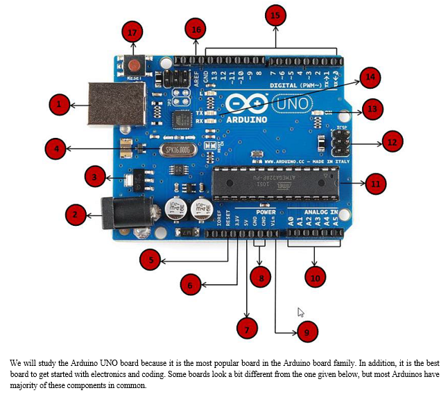
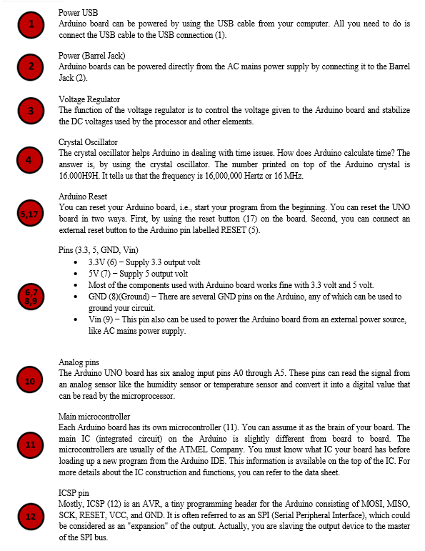
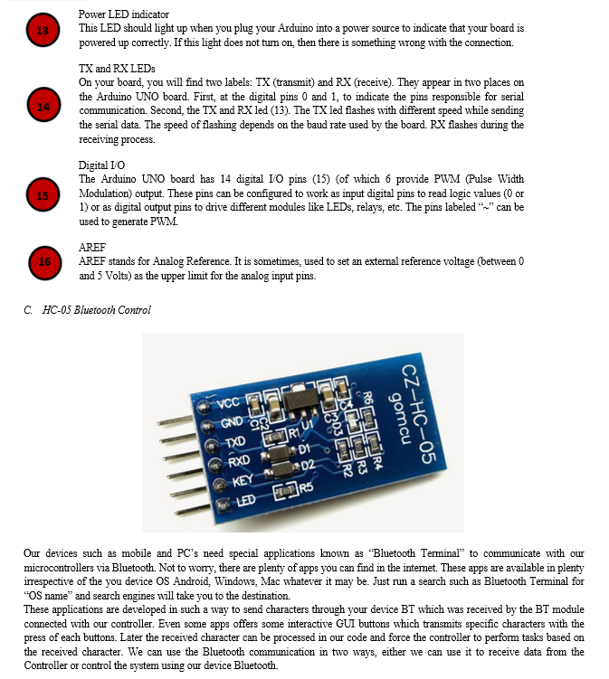
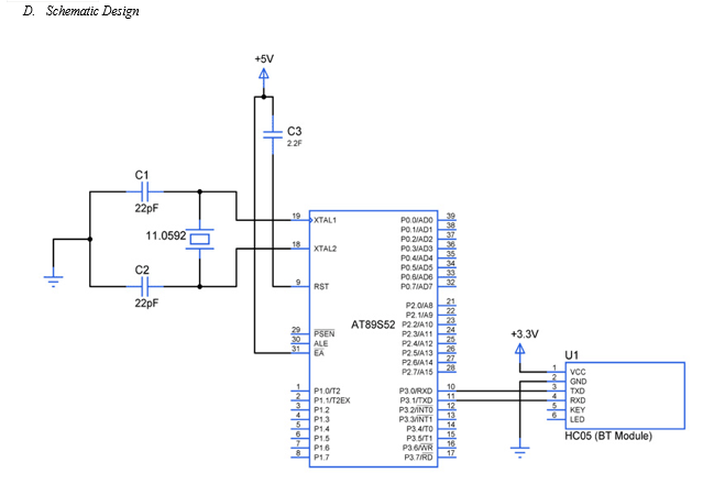
III. METHODOLOGY
A. Selection of Project
There are different types of microcontrollers available, among which we have chosen Arduino as our microcontroller. It was chosen because of its low cost and convenient operation. Choose wood as the base material of the production device. The model was designed using Solid Works software version 20.0, and then manufactured as shown in Figure 1. The material of choice for our model manufacturing is plywood. We chose this material because it provides enough strength for our model and it is easily available in the market at a reasonable price.
- Arduino Uno or similar microcontroller board
- Stepper motor or DC motor with appropriate motor driver
- Drill chuck or spindle
- Power supply for the motor
- Various mechanical components like shafts, bearings, and gears
- Limit switches for end stops
- Drill bits
- Frame or enclosure for the machine
- Various electronic components (resistors, capacitors, etc.)
- Connecting wires
- Power source for Arduino
a. Steps
- Design and Fabrication: Design the mechanical structure of the drilling machine. Consider factors like stability, rigidity, and safety. Fabricate the frame using suitable materials like aluminum extrusions or steel. Mount the motor, chuck, and other components securely.
- Motor Control Circuit: Connect the motor to the motor driver, and the motor driver to the Arduino. If you're using a stepper motor, ensure that the motor driver can handle stepper motor control. If using a DC motor, make sure to use an appropriate driver for it.
- Programming: Write the Arduino code to control the motor. You'll need functions to start, stop, and control the speed and direction of the motor. Implement safety features such as emergency stop and limit switch detection to prevent accidents.
- User Interface (Optional): You can add a user interface to control the drilling machine. This could be a simple LCD screen and a few buttons or a more advanced interface using a touchscreen or a smartphone app.
- Testing and Calibration: Test the machine to ensure that it drills accurately and reliably. Calibrate the motor control to achieve the desired drilling depth and speed.
- Safety Considerations: Ensure that all safety measures are in place. This includes enclosing moving parts, adding emergency stop buttons, and implementing software-based safety features.
- Final Touches: Once everything is working correctly, add any final touches such as painting the frame or adding branding.
b. Challenges to Consider
- Precision: Achieving precise drilling requires careful calibration and mechanical design.
- Overheating: Motors and motor drivers can overheat during prolonged use. Consider adding cooling fans or heat sinks if necessary.
- Power Supply: Ensure that the power supply can deliver enough current to drive the motor without overheating or causing voltage drops.
- Noise: Motors can be noisy, especially at higher speeds. Consider noise reduction measures if noise is a concern.
By following these steps and considering the challenges, you can fabricate and automate a drilling machine using Arduino successfully.
B. Fabrication
Fitting a drilling machine with Arduino control involves integrating the Arduino into the existing setup and establishing communication between the Arduino and the components of the drilling machine. Here's a step-by-step process to guide you through:

- Understand the Drilling Machine
a. Examine the Existing Setup: Understand the components and how they work together in the drilling machine. Identify the motor, power source, control mechanisms, and any safety features.
2. Prepare the Arduino Setup
a. Select the Arduino Board: Choose an appropriate Arduino board (e.g., Arduino Uno) based on the requirements of your project.
b. Gather Components: Collect the necessary components such as motor drivers, sensors (if needed), wires, and power supplies.
3. Mechanical Integration
a. Mounting the Arduino: Choose a suitable location to mount the Arduino board within the drilling machine enclosure. Ensure it's secure and protected from dust and debris.
b. Connect Motor to Motor Driver: Connect the motor to the motor driver (if not already done). Ensure proper wiring and connections to prevent short circuits or damage to the components.
4. Electrical Connections
a. Connect Motor Driver to Arduino: Wire the motor driver to the Arduino following the manufacturer's instructions. Typically, this involves connecting digital pins on the Arduino to control inputs (e.g., direction and speed) on the motor driver.
b. Power Supply: Connect the power supply for the motor to the motor driver. Ensure the voltage and current ratings are compatible with the motor and motor driver.
5. Sensor Integration (Optional)
a. Limit Switches: If your drilling machine has limit switches for end stops or safety purposes, wire them to the Arduino to detect the machine's position.
6. Programming
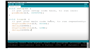
a. Write Arduino Sketch: Develop an Arduino sketch (program) to control the motor based on user input or predefined parameters. Include functions for starting, stopping, and controlling the speed and direction of the motor.
b. Implement Safety Features: Incorporate safety features such as emergency stop functionality and limit switch detection in your code to ensure safe operation of the drilling machine.
7. Testing and Calibration
a. Test Motor Control: Upload the Arduino sketch and test the motor control functionality. Verify that the motor responds correctly to commands from the Arduino.
b. Calibration: Fine-tune the motor control parameters (e.g., speed, acceleration) and sensor readings if necessary to achieve the desired performance and accuracy.
8. Integration and Final Checks
a. Secure Wiring: Ensure all connections are secure and properly insulated to prevent electrical hazards.
b. Check for Interference: Test the Arduino-controlled drilling machine under various conditions to ensure there's no interference between the Arduino and other components.
9. Safety Considerations
a. Enclosure: If the drilling machine is open, consider enclosing it to protect users from moving parts and electrical components.
b. Emergency Stop: Install an emergency stop button that cuts power to the motor in case of emergencies.
c. User Training: Provide adequate training to users on operating the Arduino-controlled drilling machine safely.
IV. LITERATURE REVIEW
There's a growing interest in using Arduino for fabricating and automating drilling machines, particularly for small-scale applications.
Here's a breakdown of key points gleaned from relevant research:
A. Motivation
- Cost-Effectiveness: Compared to expensive CNC machines, Arduino offers a low-cost solution for automating drilling processes. This makes it attractive for hobbyists, small workshops, and educational institutions [1, 2].
- Precision and Repeatability: Manual drilling can be imprecise in terms of depth and consistency. Arduino-controlled systems address this by enabling programmed drilling depths and repetitive actions, leading to improved quality and efficiency [2].
B. Design Considerations
- Functionality: The core functionality involves controlling the drilling machine's movement (typically along a single axis) and the drill's activation. This is achieved using Arduino's digital outputs to drive stepper motors or DC motors [1, 2].
- Accuracy: Studies highlight the importance of achieving good dimensional accuracy and surface finish in the drilled holes. This might involve incorporating feedback mechanisms (e.g., limit switches) for precise positioning [1].
C. Applications
- Prototyping and Small Batch Production: Arduino-controlled drilling machines are suitable for creating prototypes or producing small batches of parts requiring precise drilling patterns [2].
- Educational Tool: These systems can serve as educational tools for students to learn about automation, control systems, and basic machining principles [1].
D. Limitations
- Complexity for Large-Scale Work: While effective for small-scale applications, Arduino-controlled drilling machines might lack the processing power and control features needed for large-scale industrial drilling tasks [1, 2].
- Safety Considerations: Research around Arduino-controlled drilling machines often focuses on the technical aspects. It's crucial to ensure proper safety measures are implemented during design and operation [1, 2].
E. Future Directions
- Advanced Functionality: Future research could explore integrating additional functionalities like automatic tool change, sensor feedback for real-time adjustments, and user interfaces for improved control [1, 2].
- Standardization and Open-Source Designs: Developing standardized designs and open-source software libraries could further promote the adoption of Arduino-controlled drilling machines in various applications [1, 2].
In conclusion, Arduino offers a promising approach for fabricating and automating drilling machines, particularly for cost-conscious applications requiring precise drilling. As research progresses, we can expect advancements in functionality, user-friendliness, and safety protocols.
V. RESULTS
The key takeaway from the literature review is that Arduino-controlled drilling machines offer a cost-effective and precise solution for small-scale automation and fabrication.
Here's a breakdown of the results:
A. Advantages
- Affordable alternative to expensive CNC machines
- Improved accuracy and repeatability compared to manual drilling
- Suitable for prototyping, small batch production, and education
B. Limitations
- Less powerful for large-scale industrial applications
- Safety considerations need to be addressed during design and operation
C. Future Potential
- Integration of advanced functionalities (automatic tool change, sensor feedback)
- Development of standardized designs and open-source resources
Guide Name
Under the esteemed Guidance of
Mr. Ch.Ram prasad, M. Tech., M.S.
Assistant Professor
Conclusion
Arduino-controlled drilling machines offer a compelling solution for small-scale automation and fabrication. Their affordability and programmability make them ideal for prototyping, small batch production, and educational settings. They deliver improved precision and repeatability compared to manual drilling. However, complexity limitations make them less suitable for large-scale industrial applications. Future advancements in functionalities, open-source resources, and safety considerations hold promise for expanding the capabilities and reach of Arduino-controlled drilling machines..
References
[1] \"Arduino Cookbook\" by Michael Margolis [2] \"Arduino Programming in 24 Hours, Sams Teach Yourself\" by Richard Blum: [3] https://www.arduino.cc/ [4] https://github.com/arduino [5] https://forum.arduino.cc/t/suggestions-for-books-on-arduino-code/1182106
Copyright
Copyright © 2024 G. Lokesh, B. Suresh, B. Jay Krishna, A. V. V. Manikanta, Ram Prasad. This is an open access article distributed under the Creative Commons Attribution License, which permits unrestricted use, distribution, and reproduction in any medium, provided the original work is properly cited.

Download Paper
Paper Id : IJRASET63657
Publish Date : 2024-07-17
ISSN : 2321-9653
Publisher Name : IJRASET
DOI Link : Click Here
 Submit Paper Online

