Ijraset Journal For Research in Applied Science and Engineering Technology
- Home / Ijraset
- On This Page
- Abstract
- Introduction
- Conclusion
- References
- Copyright
Analysis of the Feasibility of a Diagrid Bracing System in Tall Buildings
Authors: Mr. Prathmesh P. Kulkarni, Er. C. A. Prasad, Dr. L. G. Patil
DOI Link: https://doi.org/10.22214/ijraset.2023.54595
Certificate: View Certificate
Abstract
The primary goal of this study is to provide a superior lateral load-resisting system. In this study, the diagrid structural system is considered, with the shear wall core present at the center part of the building and the diagrid bracings provided at the outer periphery of the structure, which is formed of steel material. The diagrid, which is made up of inclined diagonal steel sections, allows the diagonal member to function axially to resist lateral loads. Due to its structural effectiveness and versatility in architectural planning, the diagrid structural system has recently been used in tall buildings. A 14-story Diagrid composite building is selected, and its analysis and design results are presented. The Diagrid bracing system is connected to the full bays, the diagrid bracing system is connected to the mid-end bays, and the diagrid bracing system is connected to the end bays these are the three different types of models that have been studied. The diagrid bracing system has been modeled by using structural steel material, and the remaining structure has been modeled by using concrete material. A standard 60 m x 60 m floor plan has been considered. FEM-based software called ETABS has been used to model and analyze structures. A PT slab and a PT band beam have been used in the model frame for the span of 10 m. By considering all possible load combinations, all structural members made of steel and concrete are analyzed by IS: 800:2007 and IS: 456:2000, respectively.
Introduction
I. INTRODUCTION
Bracing systems are often employed in the creation of skyscrapers. It is followed by mega frame structures, diagrid structures, and three-dimensional (3D) space structures. In multistory buildings, bracing systems are often employed as a lateral stability mechanism. The Diagrid bracing system is an important structural system for providing stiffness and strength to withstand lateral loads. It is a quite an effective and affordable technique for lateral force resistance. The word ‘diagrid’ is the combination of the word ‘diagonal’ and ‘grid’. A component of the bracing system, which evolved from the traditional bracing system, is a diagrid system. It includes enormous diagonal bracings on the building's exterior, which is typically visible to the public; as a result, it also serves as an aesthetic element for architects. Thus, the field of structural engineering produces a lot of innovative ideas, such as the bare frame, beam-column moment frame, etc. This structural system is appropriate and easy to build. However, it has drawbacks, such as their poor lateral load resistance at higher heights. These lateral loads are mostly caused by wind and seismic forces. As we raise the height of the structure, wind forces begin to govern over seismic forces.
Different structural systems are developed to resist lateral forces, which include:
- Moment Frame with the Structural Wall System,
- Structural Wall System,
- Structural Wall System with Flat Slab Floor System,
- Core and Outrigger Structural System,
- Structural Wall + Frame Tube System,
- Tube-in-Tube Structural System,
- Multiple Tube System, etc.
The recent and most popular structural system that is in existence is the “diagrid structural system”. This type of structure is very reliable from the structural point of view, and it has been in use for a decade.
II. OBJECTIVES
- To compute lateral load shared by the core element, periphery columns, and internal columns.
- To analyze diagrid structures, study the diagrid systems with their changing positions to resist the lateral load with different configurations.
- To create and analyze the structural models and to review and report the following parameters:
a. To propose different configurations of cross diagonal bracing system connected to full bays, mid-end bays, and end bays and present results.
b. To observe the effect of diagrid on the minimization of lateral deflection of the structure.
c. To examine the structure’s behavior in terms of structural parameters such as modal participation mass ratio, max story drift, max story displacement, etc.
III. LITERATURE REVIEW
K. S. Moon., (2011) in his paper entitled, analyzed the structural performance and efficiency of the diagrid system in large structures with intricate shapes. The rate of twisting and the angle of tilting were studied using parametric structural models. The diagrid structure is modeled as a cantilever beam one end fixed on the ground and the other hanging. According to the repeating diagrid design, it was divided longitudinally into modules. Each module had a single level of diagrids that covered several stories. It is concluded that the core structures resist gravity loads while the perimeter diagrids resist the impending lateral load.
K. Jani & P. V. Patel., (2013) analyzed and designed a diagrid structural system for high-rise steel buildings. In his study, the buildings with different story heights are considered, such as thirty-six, fifty, sixty, seventy, and eighty-story diagrid steel structures are analyzed and designed. Based on finite elements for modeling, ETABS software is used. The entire structure was designed using IS 800-2007. A building’s structural design of the building is dominated by lateral loads because of seismic and wind effects. The internal core of the structure resists the lateral load acting on it. The internal structural system typically comprises of a braced frame with a shear wall core that resists lateral loads from the center. The external structural system consists of a framed tube and a braced frame, with internal columns and peripheral diagonal columns each resisting one of the two types of loads: gravity and lateral. Therefore, the internal columns should be designed for gravity loads only. Diagrid buildings typically do not need a core since diagrids on the building's exterior can support lateral shear.
R. D. Deshpande et al., (2015) contrasted structural systems with diagrids and conventional structures. The modeling and analysis of structural members were done using ETABS software. For the structure's analysis and design, dynamic wind loads across and along the wind direction were considered. The study's primary goal was to assess the efficacy of conventional and diagrid structural constructions. The diagrid structural system outperforms all performance evaluation criteria, including efficiency and sustainability. Comparing the construction to a traditional building with the same size and features, it exhibits comparatively less deflection. Greater weight reduction makes the structure lighter and increases its resistance to lateral stresses. When compared to the typical orthogonal building, which required 15255 tonnes of steel, Diagrid used 11247 tonnes, which is approximately 28% less. The diagrid structure featured a greater accessible area, reduced deflection, and used 28% less steel than a conventional structure.
K. Kamath et al., (2016) analyzed a diagrid structure's performance using non-linear static pushover analysis. The models under study had a circular floor layout and an aspect ratio H/B value that ranged from 2.67 to 4.26. The external bracing used in the study had angles of 59, 71, and 78 degrees. The base's breadth was fixed at 12 meters while the structure's height was adjusted in accordance. Using plastic hinges and the moment-curvature connection, the element's non-linear behavior was modeled in accordance with FEMA 356 specifications. The structure was subjected to a lateral load that increased gradually throughout the analysis until the desired displacement was achieved. The top story of the structure was gradually changed during the pushover study using the displacement control approach such that the necessary horizontal forces were going to push the structure laterally. The parameters assessed for the evaluation of the structure's seismic response include base shear and roof displacement. Studies revealed that the performance of the structure is significantly impacted by the brace angle and aspect ratio.
IV. METHODOLOGY
A. Modeling and Analysis
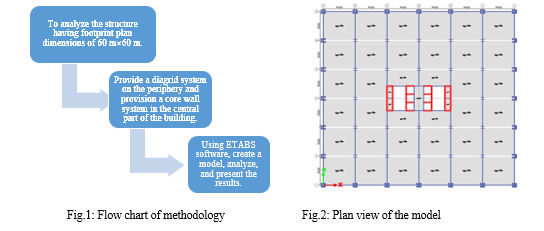
In this study, the 14-story structure with 60 m x 60 m footprint plan dimensions has been considered. The story height is 4.2 m. Pairs of bracing are placed on the building's exterior in diagrid constructions. Cross bracing connected to end, mid & end, end bays that three different models are considered about its location, and the no of bays in which it is provided. The span length between each column is 10 m. A continuous wide beam with dimensions of 1500 mm by 750 mm is provided for the structure. These beams are only spanning in one direction.
slabs with a thickness of 250 mm are provided to span over 10 m which will be considered in the design for the PT slab.
Exterior columns are 1500mm x 1500mm in dimension.
Interior columns are 1000 mm x 1000 mm in dimension.
To model Diagrid-Bracing, ISMB 500 steel section was used.


V. RESULTS
A. Base Shear & Deflection of wind & Earthquake Forces
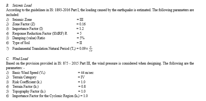
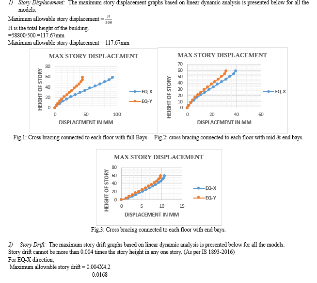
The building is primarily subject to two forms of loads. such as lateral loads and gravitational loads. The lateral loads comes into the picture because of earthquakes and wind forces. The table below shows the average value of all model’s Base shear and deflection for wind and earthquake force thus, it can be concluded that the earthquake forces are more dominant than the wind forces.
|
Forces |
Base shear |
Deflection (mm) |
|
Earthquake forces |
33347.95 |
100 |
|
Wind forces |
3771.98 |
10 |


VI. ACKNOWLEDGMENT
It gives me great pleasure to offer my heartfelt gratitude and sincere appreciation to my external guide, Er. C. A. Prasad, Metey engineering consultancy Pvt. Ltd, Hyderabad. and internal guide Dr. L. G. Patil, Department of Civil Engineering SGGSIE&T, Vishnupuri, Nanded, for giving me constant encouragement, supervision, scholarly guidance, and prompt advice throughout the research work.
Conclusion
1) After analysing the different models, it has been found that the shear wall core and outer peripheral columns attract 90% of the lateral load and all internal columns attract only 10% of the lateral load, as a result, internal columns might only be designed for gravity loads. 2) The table below lists the lateral loads experienced by the inner columns, shear wall core, and exterior columns for each of the three models. Model no Model name Load on External column (%) Load on Shear wall (%) Load on Internal column (%) 1 Cross bracing connected to each floor with end bays 51% 39% 10% 2 Cross bracing connected to each floor with mid & end bays 67.23% 29.78% 2.99% 3 Cross bracing connected to each floor with full bays 50% 39.67% 10.48% 3) The cross bracing connected to each floor model is workable to carry the lateral load efficiently. In this case, the external column takes fifty or more than fifty percent of the load, and the internal column takes ten or less than 10% of the load. 4) The cross bracing connected to each floor with a mid-end bays model is more workable to carry the lateral load efficiently. In this case, the external column takes 67.23% of the load, the shear wall core takes 29.78%, and the internal column takes 2.99% of the load so the internal column may be designed for gravity load only.
References
[1] Gu M. And Quan Y., “Across-Wind Loads of Typical Tall Buildings\", Journal of Wind Engineering and Industrial Aerodynamics 2004, pp.1147-1165. [2] Kim J., Jun Y., and Lee Y.H., “Seismic Performance Evaluation of Diagrid System Buildings\", 2nd Specialty Conference on Disaster Mitigation, Manitoba, June 2010. [3] Moon K.S., “Material-Saving Design Strategies for Tall Building Structures\", CTBUH 8th World Congress, Dubai, March 2008. [4] Leonard J., “Investigation of Shear Lag Effect in High-Rise Buildings with Diagrid System\", M.S. thesis, Massachusetts Institute of Technology, 2007. [5] Moon K.S., “Dynamic Interrelationship between Technology and Architecture in Tall Buildings\", Ph.D. dissertation, Department of Architecture, Massachusetts Institute of Technology, 2005. [6] IS: 875(Part-3)-1987. Code of practice for design loads (other than earthquake) for buildings and structures, wind loads. Bureau of Indian Standard, New Delhi. [7] IS: 1893(Part-I)-2002. Criteria for Earthquake Resistant Design of Structures. Bureau of Indian Standard, New Delhi. [8] IS: 800-2007. General Construction in Steel - Code of Practice. Bureau of Indian Standard, New Delhi. [9] ETABS Nonlinear Ver. 9, Extended Three-Dimensional Analysis of Building Systems, Computers and Structures Inc. Berkeley, CA USA, 2006 [10] Jani Khushbu, “Analysis and Design of Diagrid Structural System for High Rise Steel Buildings”, M. Tech. Dissertation, Nirma University, Ahmedabad, 2012.
Copyright
Copyright © 2023 Mr. Prathmesh P. Kulkarni, Er. C. A. Prasad, Dr. L. G. Patil. This is an open access article distributed under the Creative Commons Attribution License, which permits unrestricted use, distribution, and reproduction in any medium, provided the original work is properly cited.

Download Paper
Paper Id : IJRASET54595
Publish Date : 2023-07-03
ISSN : 2321-9653
Publisher Name : IJRASET
DOI Link : Click Here
 Submit Paper Online

