Ijraset Journal For Research in Applied Science and Engineering Technology
- Home / Ijraset
- On This Page
- Abstract
- Introduction
- Conclusion
- References
- Copyright
Flow Analysis of Centrifugal Compressor using ANSYS
Authors: Garima Awasthi, B. K. Chourasia, S. Rai
DOI Link: https://doi.org/10.22214/ijraset.2024.63784
Certificate: View Certificate
Abstract
The aerodynamic and structural designs of the impeller are vital to the functioning of the entire compressor stage in centrifugal compressors. In contrast to previous years, there has been a greater demand for industrial centrifugal compressors to operate with greater efficiency and operational range. Although the efficiency of low-pressure-ratio centrifugal compressors has nearly achieved its maximum, intermediate and high-pressure ratio machines still lag behind the state-of-the-art in terms of efficiency. Maintaining maximum efficiency while extending the working range is a challenging task in centrifugal compressor design. Furthermore, a single design must be usable globally due to product globalisation, even in the face of technological disparities and variances in electricity frequency of up to 10 percent in some nations. Often operating at different rotational speeds, centrifugal compressors add another layer of complexity to the impeller structural design. A full-3D impeller design that is optimised for both structural integrity and aerodynamic performance is shown in this study .For air conditioning systems of the future, centrifugal compressor performance must be improved. This research focusses on systematic numerical simulation, a computationally efficient method of optimising centrifugal compressor performance. ANSYS simulations are used in conjunction with a thorough literature review on the aerodynamic behaviour of materials used in centrifugal compressors. For the purpose of performing flow simulations under subsonic circumstances with suitable boundary conditions and grid independence checks, geometric modelling was completed using CATIAV5R22 and imported into ANSYS. Tests were conducted using various aluminium materials and mass flow rates, and enhanced efficiency findings were confirmed by comparison with experimental data. Materials Processing and Characterisations is in charge of peer review.
Introduction
I. INTRODUCTION
The technique of keeping a controlled interior climate is known as air conditioning. All around the world, including the arid regions of Africa and Antarctica, there are humans. There are very few temperate zone areas where year-round comfort is possible without air conditioning. Artificial cooling has long been thought to be advantageous. Primitive cooling methods like snow, ice, and cold water have been used by humans throughout history, but they were considered a luxury rather than a need. It was unclear what the fundamental principles of atmospheric evaporation were. In the past, humans warmed themselves by lighting open fires in caverns. In today’s world, air conditioning (AC) systems are essential for preserving indoor thermal comfort and air quality in all types of buildings—residential, commercial, and industrial. The air conditioning compressor, a mechanical device that compresses refrigerant—a necessary component for the heat exchange process that powers the refrigeration cycle—is crucial to the operation of these systems. The components of the air conditioning system include a compressor for compressing refrigerant, an evaporator for evaporating refrigerant, a condenser for condensing refrigerant, two expansion devices for throttling refrigerant, and refrigerant injection following branching.
II. CENTRIFUGAL COMPRESSOR
By definition, centrifugal compressors are fluid-dynamic devices that raise a fluid’s pressure by transforming mechanical energy into potential energy. They are not like pumps in that they work by first speeding the flow through rotating blades and then slowing it down in a diffuser to raise the static pressure. In contrast, a piston’s displacement causes a pressure rise in a pump; during the device’s entire operation, the fluid remains at rest. Another distinction has to do with how the machine operates. When pressure is raised through fluid displacement, one speaks of positive displacement compressors; in other cases, when pressure is raised by the action of revolving blades, one speaks of dynamic compressors, or turbomachinery, when mechanical energy is provided by a turbine. Automotive engines frequently use dynamic compressors to boost performance. In contrast to volumetric compressors, which need large amounts of space and weight to function, dynamic compressors provide a significant rise in pressure with a very small increase in weight and size.
This is mostly because of the high velocities that the flow reaches as a result of interacting with the rotating elements. Second, compared to volumetric compressors, the portion of internal volume devoted to the flow at a given flow rate is substantially larger.
A. Centrifugal Compressor Diagram
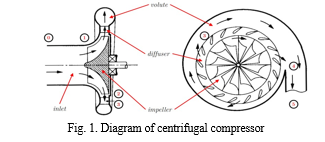
The four primary components of a centrifugal compressor are the inlet, impeller, diffuser, and volute. To ensure a specific degree of pressure increase, each of them is necessary. Each compressor is unique from the others primarily due to the arrangement, dimensions, and form of its parts; the overall design, however, can be boiled down to these four elements. It displays the centrifugal compressor’s qualitative structure. The image serves as a reference point for the entirety of the thesis and reports on the customs implemented for each significant site. Radial compressors are typically used in conjunction with radial turbines to create turbochargers in automotive applications. In this setup, the turbine’s rotation converts the thermal energy of the combustion exhaust gases into mechanical energy and produces torque, which is then transferred to the compressor via a rotating shaft. As a result, the turbine and compressor are rotating at the same speed.
III. LITERATURE REVIEW
- Jian and Hu’s (2008) [2] goal is to determine the axial-flow compressor rotor performance by comparing the outcomes of rotors with and without casing treatment, with and without intake pressure distortion. In order to perform this numerical analysis, unstable 3D Navier Stokes equations were utilised. NUMECA FINE was the tool utilised to carry out the flow simulation. The steady-state simulations of a single blade passage are first performed by taking use of the symmetry present in the circumferential grooves. By taking a tenth of the rotor blade passages in the compressor stage, an extra 3D time accurate analysis is generated. It is evident from this study that the compressor stage efficiency is increased by the groove casing treatment. This study’s flow conditions were restricted to low-speed Mach numbers, which also meant that tip leakage was reduced to minimal losses.
- When the rotor blade experiences vibration phenomena, the performance of an axial-flow compressor was investigated by Min, Duffy, Choi, Provenza, and Kray (2013) [3] for various pressure load circumstances. The primary goal of this research work is to lessen this effect through an examination of piezoelectric vibration control. This will assist in creating blade models that are thinner, more capable, and less susceptible to vibration-related damage. The goal of the research is to compare computational and experimental results while first analysing a finite element composite model coupled with a resistor (R), an inductor (L), and a capacitor (C) (RLC) circuit to replicate spinning blade circumstances. The findings demonstrate the major advantages of reducing the blades’ piezoelectric vibrations. To adapt it to the engine blade system of commercial aeroplanes, however, more research is required.
- Suder et al. (2001) [4] set out to investigate the impact of steady tip injection on compressor stability using a single rotor stage. Finding the best way to maximise compressor stability for a specific injected flow level was another goal of their effort. The methodology of the work involved further experimental investigation on the injector configuration and its settings, followed by the use of CFD simulations with a mass-injection model to explore the fluid mechanics process by which tip injection promotes compressor stability. In order to investigate maximum stabilisation criterion, the injection parameters—such as flow momentum, velocity, and injector distribution—were changed. The CFD analysis led to the conclusion that injector effectiveness is dependent on the injector exit axial velocity and momentum, and that injectors increased stability by reducing blade loading and incidence at the tip. The experimental findings suggested that the mass averaged axial velocity at the blade tip is the parameter that directly correlates with range extension and that it is unaffected by the configuration of the injectors. Although the study only looked at one rotor stage, the authors think that adding injectors to the intake and mid-stage might improve the stability of a multistage compressor.
- In an axial compressor operated under transonic circumstances, Cong-Truong Dinh, Heo, and Kim (2015) [5] evaluated blade tip injection using NASA rotor 37. In addition, a brief overview of casing groove was given. 3D Navier-Stokes equations served as the foundation for the performance study. The study looks into how operational and dimensional characteristics affect performance metrics like adiabatic efficiency, total pressure ratio, and stall margin. The combination of tip ejection and injection in a casing groove was shown to be more effective than using injection alone. To improve the compressor’s performance, additional geometry optimisation in the ejection and injection combination can be carried out.
- SUN A transonic flow compressor blade stall initiation model was established by Xiaofeng, Dakun , and Weiwei (2011) [6]. This model takes into account the impacts of shock waves and stability. In order to obtain steady equations for the solution of an unsteady flow field, a set of homogeneous equations is derived using the mode-matching technique. Experimental data and numerical analysis are used in the research. The impact of centrifugal force caused by radial velocity has not been taken into account in this model, which could provide more accurate findings.
- A numerical investigation on the rotor’s tip clearance flow under transonic compressor circumstances was carried out by Ren and Chunwei (2016) [7]. The Spalart-Almaras turbulence model is discretised in physical space using 3D Navier-Stokes equations by the use of a discontinuous Galerkin approach. The rotor has a blockage indicator installed in order to determine the amount of obstruction in the transonic flow. The obstruction that affects the tip clearance flow increases at first and then diminishes as the cross-section advances downstream. When the blade clearance is introduced in a mass flow rate condition that is 98
- Zhihui and Liu (2017) [8] improved how blade-end treatment was applied to axial-flow compressors. The loading distributions of the blades are altered in spanwise directions by the blade-end treatment. Through optimisation of the blade end treatment, there was less loss in the shroud area. According to experimental and numerical studies, tip leakage losses cannot be effectively reduced by applying the end bend. In the compressor, NASA Rotor 35 was taken into account. In order to optimise it and validate the flow mechanisms, genetic algorithms and an artificial neural network model were used. Combining the optimisation algorithms with the summarised flow control mechanisms is a preferable approach to take into consideration because of the limitations on processing power. This will lower the computational expenses.
- The acoustics in a two-stage axial compressor with a changeable pitch and the impact on performance when five various blade tip patterns are used were studied numerically by Xuemin, Zhang, and Chunxi (2017) [9]. A fan model is numerically simulated as part of the computational process by using CFD with various blade designs. According to the study’s findings, the direct groove tip outperforms double, forward, and reverse step groove tips. A reverse groove tip’s effectiveness is constrained to low mass flow rates.
- Shaobing and Jingjun (2016) [10] carried out a numerical analysis to ascertain the performance variance at various locations of a blade tip winglet for a highly loaded compressor rotor subjected to the transonic regime.
- Poursaeidi, Tafrishi, and Amani (2017) [11] looked atthe effects of solid particles that erode the compressor’s blades during the entry stage. Both computational and experimental analysis were used in the investigation. The rotor blades in the configuration were made of AISI Custom 450 stainless steel. The leading edge around the shroud case, which is the hub and tips of the stator blades, is where the erosion was most successful, depending on the paths taken by the quartz and sand particles. Thus, the relationship between erosion rate and angle—which reaches its maximum at 20° and becomes negligible at 90°—is demonstrated. But it was found that the inlet guide vanes erode at the lowest rate because the solid particles have no effect on the suction surface.
- Zhou, Zhao, Cui, and Jianzhong (2017) [10] looked intothe axial effect of recirculation in the slots and examined the flow characteristics at four distinct points near the blade tip. Through the use of unstable numerical simulations, the NASA rotor 67 numerical model was created using EURANUS. According to the findings, moving slots upstream or downstream resulted in less benefit. It is determined that the stall margin improvement is more significantly impacted by the recirculation intensity in the slots.
- In order to use the Brayton cycle while using solar power, Daabo, Saad Mahmoud, Al-Dadah, and Al Jubori (2017) [12] carried out numerical study on variable stage axial and radial turbines. CFD is used to calculate the efficiency and power production at different boundary conditions, as well as to visualise the flow characteristics inside the turbine. The findings showed that, under off-design conditions, the dual stage turbine outnumbers the single-stage turbine in terms of power delivered. The ideal arrangement between the single stage radial turbine and the dual-stage axial turbine may have been found through additional investigation.
- A study on the effects of circumferential grooves casing treatment in an axial-flow compressor was carried out by Mao, Liu, and Zhao (2018) [14]. In order to identify unstable flow behaviour and the reasons underlying it, the effects are examined on counter-rotating compressor stages, thereby improving stability. EURANUS International’s CFD solver was used to do the simulations. Only two rotors were used because of computational cost limitations. The findings indicate that while there is a significant improvement in performance close to the stall zone, the groove casing treatment has little influence at the point of maximum efficiency. Because there are more than one blade, the actual performance numbers are lower than the obtained ones. Reid and Moore (1978) conducted well calculated theoretical and practical research on high-loaded and high-speed axial-flow compressors.
- Wang, Lu, Liu, and Hu (2018) [14] conducted an unsteady numerical research for tip clearance flow on a compressor operating in transonic conditions. A CFD solver entered the compressor’s first stage rotor, and computations were done both steadily and unsteadily. The findings demonstrated that on a multi-passage construction, the rotational instability phenomena takes place along the circumferential direction. Each blade exhibits synchronous oscillations under the coswirl inlet conditions because of the weak interaction between the shock near the stall area and the tip leakage vortex.
IV. METHODOLOGY
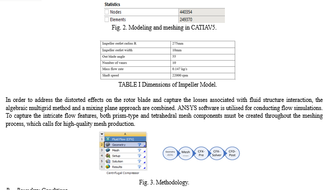
The work’s technique is shown in Fig. 2. The software utilised for this thesis project is Ansys Workbench, with the CFD code CFX. The work flow and the module used for CFD simulations are displayed in the figures below. A geometry can be produced using CATIAV5R22 or Design Modeller. It can also be imported from a CATIA program that is utilised externally. After the geometry is finished, the mesh cell is used to divide it. The geometry is divided into smaller cells in this stage by applying a grid, and each cell will subsequently be solved for. Subsequently, the setup cell incorporates boundary conditions such as temperature, pressure, rotational speeds, turbulence models, etc. After completing this, the CFX-Solver can be used to remedy the issue. Post-processing the solver’s result file is the last step. This is completed in CFD-Post using either graphical vector fields or text fields for the parameters.
The description of the models used in classification is as follows-
A. Geometrical Modelling and Meshing
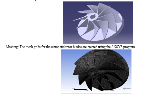
CATIAV5R21 is used to build the centrifugal compressor’s entire geometry. The complex design of the compressor can be precisely modelled with the help of this tool.
B. Boundary Conditions
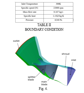
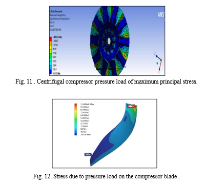
Sufficient boundary conditions are implemented at subsonic velocities to guarantee the dependability of the numerical examination outcomes. The simulations are run at different mass flow rates, and to improve accuracy, a grid independence check is carried out. The simulations are finished using subsonic flow parameters and atmospheric sea level settings. For the baseline analysis, flow was initially finished using standard sea level conditions. The overall temperature at the input is fixed to 300 K. For the base line study, a solid material known as aluminium (Al) was chosen as the medium. Afterwards, distinct materials were chosen for the centrifugal compressor’s structural and flow analyses. The three-dimensional Navier Stokes equations in this work are solved using the turbulence model K-e used for the fluid flow investigation. 22,000 rpm was chosen as the starting blade speed for the base line circumstances. The centrifugal compressor mass flow rate of 0.167 kg/sec is the specified boundary condition, which is chosen normal to the boundary in the direction specification procedure. simulations that are calculated from the inlet and chosen as a reference zone. The air’s specific heat value in the far field domain was chosen to be 1.4. The implicit approach and the flux type ROE-FDE were used in order to improve the consistency of the centrifugal compressor blade vortices. Selected under spatial discretisation is the first order upwind far field. Iterations of the flow begin at the compressor flow domain’s inlet. In order to improve the trustworthiness of the flow simulation results, the convergence requirements for this flow analysis are set at 0.00001. Following the convergence criteria’s successful completion, the ANSYS module provided the full flow solver, which is also shown below. The structural analysis was done for the improved aero mechanical features once the flow simulation was finished. The tip clearance gap was kept at 0.31 throughout the analysis to provide a more efficient flow. Additionally chosen is the non-slip, smooth, and adiabatic default scaled wall function. The flow analysis treats all of the simulations as subsonic steady states, with a time step of 0.5 to 1.0 for the convergence solution. Double precession model was chosen in order to produce the most accurate centrifugal compressor simulation findings in this paper work.In this structural analysis, 6240 pa of pressure was applied. In order to do the structural analysis, a hollow shaft for the fixed support and blades that were regarded as the fluid-solid interface (FSI) were created. Determining the effects of load on the physical structure and its components is essentially the goal of the structural study of centrifugal compressors. All structures that need to support the intended load are included in the scope of this kind of pressure load analysis. With success, the compressor blade (10 faces) was finished. Total deformation, force reaction, moment reaction, equivalent stress, and maximum primary stress were the results of the integrated fluid structural interaction (FSI) analysis. For improved consistency, the same conclusions were verified using experimental data sourced from published works.
V. RESULTS AND DISCUSSION
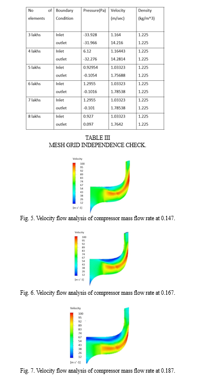
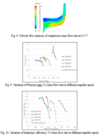
The flow margin between the surge and choke points served as the foundation for the whole numerical analysis. The flow solver successfully finished the baseline analysis in accordance with the off-design circumstances using the initial boundary conditions. The simulation’s output and the experimental data agree quite well. After that, the analysis was repeated using a new choice of materials for the various mass flow rate circumstances at 100 percent design speed. Finding the surge point proved to be a challenging task for both the structural and flow studies of centrifugal compressors. However, because of the component’s friction and pressure losses, the compressor’s flow behaviour somewhat oscillated under the original mass flow rate settings. The flow convergence solution did, however, continue to maintain at 2000+. The analysis also shows that, in comparison to the baseline analysis, the new operating range values were attained at the maximum adiabatic efficiency. Furthermore, at 22,000 rpm, the compressor impeller’s slower speed has a higher mass flow rate. A grid independence check was conducted for all the parameters of the blade. The change in the mesh size was parameterized by the change in the global size factor. Number of mesh nodes ranging from 3 lakhs to 8 lakhs was considered. The result attained stability after 4 lakhs nodes in most of the properties. Table 3 show the grid independence. Additionally, the obtained value has been verified by the outcome of the experiment. To get the most performance out of the centrifugal compressor at various grid sizes and mass flow rate values, a research of grid independence has been conducted. The mass flow rate and suitable grid size that exhibit the highest pressure ratio have been identified. Through a study of grid independence, it was discovered that density remained nearly constant with just small variations throughout the simulation. therefore density is not discussed. Additionally, it was noted that the compressor blade’s velocity varied according to the mass flow rates and the flow separation across the blade. The mass flow rate range of 0.147 kg/sec to 0.187 kg/sec was studied in fig.5-8. The figure 5 below illustrates how there is a significant amount of flow separation on the suction side of the compressor blade at a mass flow rate of 0.147. On the other hand , the fig.7 illustrates mass flow rate at 0.187 kg/sec does not vary significantly within the relatively limited range of the mass flow rate. Under all flow circumstances, the pressure side of the blade experiences the velocity propagation at 100 percent of its design speed. Plots showing the compressor’s RPM and pressure ratio at maximum value, both within the surge and choke regions, indicate the adiabatic efficiency.
The highest stress that the shroud side can withstand following the structural study calculation. The structural analysis’s performance likewise veered to the blade’s shroud side. When compared to the baseline analysis, the work that was performed and reached at 23000 RPM produced the best matching results. The entire analysis was kept at the design speed pressure of 100 percent, as stated in the conditions. Nonetheless, since the baseline study was finished during the flow analysis process, the centrifugal compressor’s calculations are at full design speed. The results of the numerical analysis were displayed in Figs. 11–12. The equivalent stress, total deformation, maximum primary stress, and stress resulting from pressure load on the blade were also well computed.
Conclusion
This comprehensive structural and numerical analysis work’s primary contribution is the use of CFD to identify centrifugal compressor performance. At 23000 RPM and a mass flow rate of 0.167 kg/sec, the maximum performance was achieved. There is less fluid loss to the compressor impeller blade due to the stress levels found higher at the shroud side than the hub side. The simulation’s was established at a mass flow rate of 0.167 kg/s . A study on grid independence has been conducted in an effort to the change in the global size factor. Number of mesh nodes ranging from 3 lakhs to 8 lakhs was considered. The result attained stability after 4 lakhs nodes in most of the properties.Table 3 show the grid independence maximise the pressure ratio following the completion of numerous simulations on various grid sizes. The highest pressure ratio was discovered to be attained at four lakhs element size and different mass flow rates at the intake. The obtained findings demonstrate that the new pressure ratio outperformed the baseline. At a mass flow rate of 0.167 kg/s as the impeller speed increases pressure ratio and isentropic efficiency increases. Consequently, it was determined that improved performance was attained at 0.167 kg/s. According to the structural analysis, the compressor is capable of maintaining its structural integrity while operating. Therefore, it may be concluded that the structural analysis of the centrifugal compressor indicates that there has been no deformation at the specified boundary conditions
References
[1] Mostefa, B., Kaddour, R., Embarek, D., Amar, K. (2021). Analysis and Optimization of the Performances of the Centrifugal Compressor Using the CFD. International Journal of Heat Technology, 39(1). [2] Jian, H., Hu, W. (2008). Numerical investigation of inlet distortion on an axial flow compressor rotor with circumferential groove casing treatment. Chinese Journal of Aeronautics, 21, 496–505. doi:10.1016/ S1000-9361(08)60166-1 [3] Min, J. B. Duffy, K. P., Choi, B. B., Provenza, A. J., Kray, N. 2013. “Numerical modeling methodology and experimental study for piezoelectric vibration damping control of rotating composite fan blades.” 11 June [4] Jian, H., Hu, W. (2008). Numerical investigation of inlet distortion on an axial flow compressor rotor with circumferential groove casing treatment. Chinese Journal of Aeronautics, 21, 496–505. doi:10.1016/ S1000-9361(08)60166-1 [5] Min, J. B. Duffy, K. P., Choi, B. B., Provenza, A. J., Kray, N. 2013. “Numerical modeling methodology and experimental study for piezoelectric vibration damping control of rotating composite fan blades.” 11 June [6] Suder, K. L., Hathaway, M. D., Thorp, S. A., Strazisar, A. J., Michelle, B. (2001, January). Bright compressor stability enhancement using discrete tip injection.Journal of Turbomachinery, 123(1), 14 - 23. [7] Dinh, C.-T., Heo, M.-W., Kim, K.-Y. (2015). Aerodynamic performance of transonic axial compressor with a casing groove combined with blade tip injection and ejection. Aerospace Science and Technology, 46, 176–187. doi:10.1016/j.ast.2015.07.006 [8] Xiaofeng, S. U. N., Dakun, S. U. N., Weiwei, Y. U. (2011). A model to predict stall inception of transonic axial flow fan/ compressors. Chinese Journal of Aeronautics, 24, 687–700. [9] Ren, X., Chunwei, G. (2016). A numerical study on the tip clearance in an axial transonic compressor rotor. Applied Thermal Engineering, 103, 282–290. doi:10.1016/j.applthermaleng.2016.04.082 [10] Hossein, K. (2017). Parametric study of injector radial penetration on stalling characteristics of a transonic fan. Aerospace Science and Technology, 66, 112–118. doi:10.1016/j.ast.2017.02.020 [11] Xuemin, Y., Zhang, J., Chunxi, L. (2017). Effect of blade tip pattern on performance of a twin-stage variable pitch axial fan. Energy, 126, 535e–563. doi:10.1016/j. energy.2017.03.057 [12] Zhou, X., Zhao, Q., Cui, W., Jianzhong, X. (2017). Investigation on axial effect of slot casing treatment in a transonic compressor. Applied Thermal Engineering, 126,53–69. doi:10.1016/j. applthermaleng.2017.07.165 [13] Alone, D. B., Kumar, S. S., Thimmaiah, S. M., Mudipalli, J. R. R., Pradeep, A. M., Srinivasan, R., Iyengar, V. S. (2016, September). Stability management of high speed axial flow compressor stage through axial extensions of bend skewed casing treatment. Propulsion and Power Research, 5(3), 236–249. doi:10.1016/j.jppr.2016.01.009 [14] Mao,X.,Liu,B.,Zhao,H.(2018).Numerical analysis of the circumferential grooves casing treatment in a counter-rotating axial flow compressor. Applied Thermal Engineering, 130,29-39.doi:10.1016/j.applthermaleng.2017.11.044
Copyright
Copyright © 2024 Garima Awasthi, B. K. Chourasia, S. Rai. This is an open access article distributed under the Creative Commons Attribution License, which permits unrestricted use, distribution, and reproduction in any medium, provided the original work is properly cited.

Download Paper
Paper Id : IJRASET63784
Publish Date : 2024-07-27
ISSN : 2321-9653
Publisher Name : IJRASET
DOI Link : Click Here
 Submit Paper Online

