Ijraset Journal For Research in Applied Science and Engineering Technology
- Home / Ijraset
- On This Page
- Abstract
- Introduction
- Conclusion
- References
- Copyright
Study of Fluid Flow and Heat Transfer in Microchannel Heat Sinks for Electronics Cooling Application
Authors: Kasukurthi Vardhan, C. Naga Bhaskar, S Venkateswara Rao
DOI Link: https://doi.org/10.22214/ijraset.2024.63895
Certificate: View Certificate
Abstract
Today’s age of rapid technological advancements has led to a significant rise in the demand for high-performance electronic chips with high power density. Effective thermal management of such high-power density systems is crucial for their performance, life and reliability. Growing trends of miniaturization and densely packed circuits have necessitated the development of optimized cooling methods, particularly for high-density electronic chips and flexible microelectronic devices. Amongst the presently available cooling techniques such as passive air cooling, forced air cooling, microchannel heat sink, liquid cold plates cooling and heat pipe, the microchannel heat sink technique stands out from the rest owing to its high rate of heat dissipation due to larger surface area to volume ratio. Current work explored three new enhancements in micro channel heat sink (MCHS) for electronic cooling. The new design have different geometry and different enhancement techniques compared with respect to the enhancement over their respective conventional domain. Three dimensional computational models based on finite volume approach were created incorporating the enhancement techniques and analysed numerically in ANSYS Workbench.
Introduction
I. INTRODUCTION
Electronic components are getting smaller and smaller, due to which heat generated per unit area is getting bigger. For example, the computers have moved from desktop to wrist watch. In 1970 only a few thousand transistors were placed in a chip, by 2006, one billion were fitted and in 2019, 60 billion transistors are packed in a chip. This results in generation of huge amount of heat in a small space. More than 70% of failure in electronic components is due to thermal mismanagement. Efficient removal of the heat is the major challenge faced by the electronics industry.
Electronics is now a multi trillion-dollar industry having a growth rate of 5 to 8%. Electronics has influenced the day to day activities of all human beings. Automotive, consumer electronics, computers, communication, medical, military are some of the applications of electronics. Electronic packaging is an art of providing a suitable environment to the electronic products for continuous reliable performance. Ergonomics, manufacturing, maintenance, thermal management, shock and vibration are some of the mechanical design aspects to be considered in electronics packaging. Since millions of circuits are placed in a small space, generation of large amount of heat (100 W/cm2 to more than 200 W/cm2) takes place. A suitable mechanism to remove this heat is required for prolonged life and reliability of electronic components.
Fan assisted air cooling for electronic components were prominent earlier but have reached the limit of cooling capacity. Water cooled (single phase) microchannel heat sink (MCHS) is one of the promising methods of thermal management of electronic component. Microchannel heat sink is a set of parallel channels having hydraulic diameter between 100 to 1000 microns, length of 5 mm to 35 mm and is fabricated directly on silicon wafer or on copper or aluminium block. Compact size, high surface to volume ratio, low coolant inventory, ability to be mounted on chip to form monolithic configuration are some of the important features of microchannel heat sink. Microchannels with rectangular shape and running parallel to each other are the conventional MCHS used by earlier researchers for heat removal from small spaces.
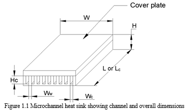
MCHS is described by overall dimensions such as length (L), breadth (W) and height (H) while the dimensions of a single channel are length (Lc), width (Wc) and depth (Hc) as shown in figure 1.1. The width of wall (Ww) separating the neighbouring channels is also an important dimension and is usually equals to channel width (Wc).
Silicon, copper or aluminium is commonly used material for MCHS. Water, Nitrogen, phase change materials and nano fluids are used as coolants. Water (Single phase and two phase) has been used by majority of researchers. Tuckerman and Pease [1] were the first researchers to use microchannels in electronic cooling in 1981. They etched microchannels 50 μm wide and 300 μm deep on the back side of silicon wafer. Using de-ionised water as coolant they were able to dissipate heat and attain thermal resistance of 0.09°C/W over 1cm2 area. Since then, huge amount of work is done in the development of microchannel heat sink for electronic cooling. Microchannels of various shape, size and materials have been designed and tested by researchers.
The maximum overall dimensions of conventional microchannel heat sink reported by researchers are 35mm x 35mm, while the average overall dimensions are 20mm x 20mm. The single phase, liquid cooled microchannel heat sink mostly has laminar flow type due to the short length scale of channel. If we consider a single microchannel, the velocity of the liquid near wall is zero and maximum at the centre of the channel creating a parabolic velocity profile; in thermal boundary layer the liquid near the wall surface gets heated while the one in the core region is unaffected by the heat. More heat transfer takes place at the entrance region due to thermo-hydraulic entrance effects, and the heat transfer reduces along the channel length resulting in thickening of boundary layer, sensible heat gain by the liquid and rise in temperature along the length of microchannel. Due to the shorter channel length, the liquid passes quickly through the channel and the core part of liquid is unable to remove heat generated at the channel base region.
Near the outlet region, high temperature gradient is present between wall surface and liquid in channel core which indicates less heat absorbed by the liquid. This is due to the thick boundary layer which is a major roadblock for the attainment of higher thermal efficiencies in microchannel. Thus, there are some issues with conventional microchannel heat sink which if sorted can improve its performance. A need is felt to have a mechanism to break the thick boundary layer and mix the liquid at different temperatures within the channel which leads to more heat removal from channel walls. Fundamentally, too, for better performance, it is better to have the flow in continuously developing state than a fully developed one in a channel.
Philips [3] extended the theoretical analysis of Tuckerman and Pease [1] to channels having small to large aspect ratios, for developing and fully developed flows, smooth and roughened channel surface. Variable property effects are included for the chip material and coolant. Thermal spreading at the periphery of simulated integrated heat source is also accounted for using simplified one-dimensional models. The numerical analysis results clearly showed that the same thermal performance can be obtained by increasing the channel width from that suggested by analytical results of Tuckerman and Pease [1]. Increasing the channel width causes the flow to become less fully developed at the channel exit. The larger widths help in keeping pumping power requirements below 10 W and are also easier to fabricate. For a heat source of 0.25 cm square heat source, the indium phosphide microchannel heat sink has been tested to a pressure drop of 414 kPa and a thermal resistance as low as 0.072 °C/(W/cm2).
Perret et al. [4] modeled and optimized microchannel design using silicon technology. Microchannels are fabricated using bulk micro-machining on backside of silicon wafer. Another wafer with inlet outlet nozzles and microchannel is fabricated and both wafers are joined by direct bonding technique. The configuration reduces the cooler overall dimensions, reduces the thermal resistance and is compatible with integrated circuits fabrication process. The heat sink dissipated heat flux of 100 W/cm2 with an increase in junction temperature by 60 °C.
Qu and Mudawar [5] investigated numerically and experimentally the pressure drop and heat transfer characteristics of single phase water cooled microchannel heat sink. Rectangular microchannel having a width of 231 μm and height of 713 μm were fabricated on copper block with polycarbonate plastic cover plate. The microchannel was subjected to two heat flux levels of 100 W/cm2and 200 W/cm2 and cooled by de- ionized water having Reynolds number from 139 to 1672. Numerical analysis was done by solving the conjugate heat transfer problem which involved the simultaneous determination of temperature field in both liquid and solid regions. They concluded that both experimental pressure drop and temperature data is in excellent agreement with numerical predictions.
II. NUMERICAL ANALYSIS OF MICROCHANNEL
Microchannels with rectangular shape and running parallel to each other are termed as the conventional MCHS. To improve the thermo-hydraulic performance of conventional MCHS, new enhancements are proposed. Three new MCHS designs viz. enhanced LV- MCHS, enhanced PF-MCHS and enhanced LP-MCHS which employ flow disturbance methods such as secondary channels and flow disturbing pins are described first and then analysed numerically.
A. Enhanced LV-MCHS
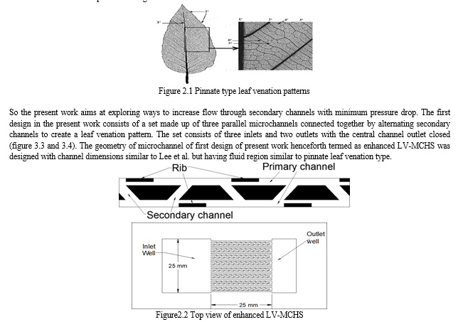
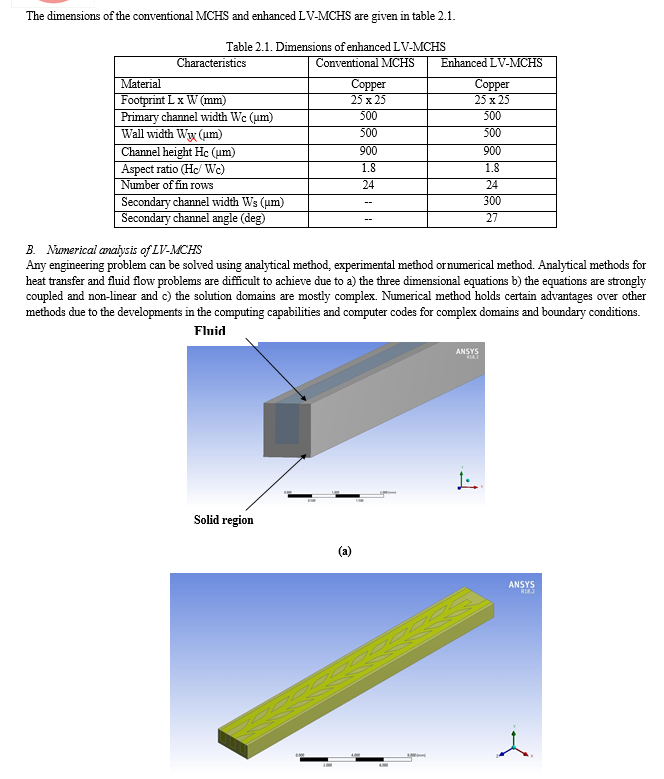
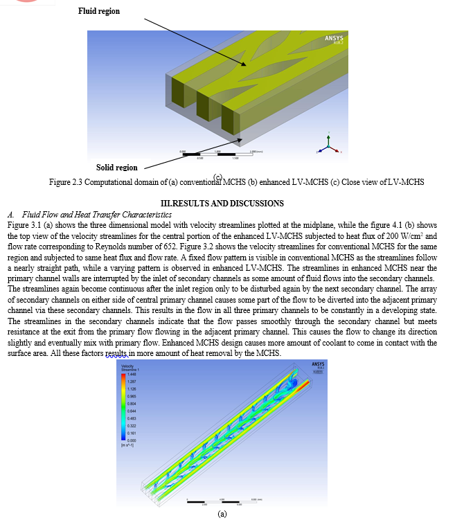
The enhanced LV-MCHS is based on leaf venation network that exist in nature. Leaf venation is branching of veins that spread across the leaf to provide structural support and transport of water, minerals and food energy from and to the plant. Different venation patterns are formed due to the presence of various orders of veins. In pinnate type leaf venation (figure 2.1), the primary (1st degree) and secondary (2nd degree) form the major structural veins of the leaf, while the tertiary (3rd degree) and higher order veins though of smaller size, cover the major portion of the leaf. Sample leaves of pinnate type venation were observed under Zeiss microscope (figure 3.2) and its dimensions noted. After studying the dimensions of various pinnate type leaves, the enhanced MCHS with leaf venation pattern is designed.
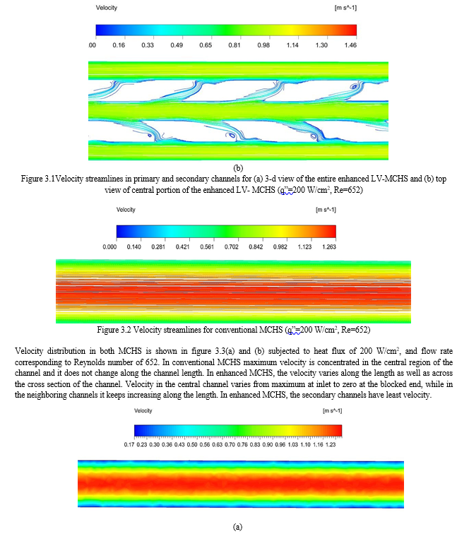
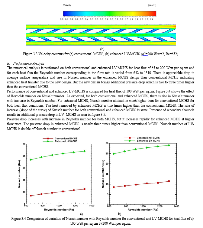
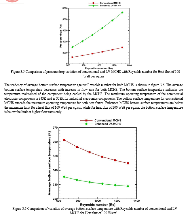
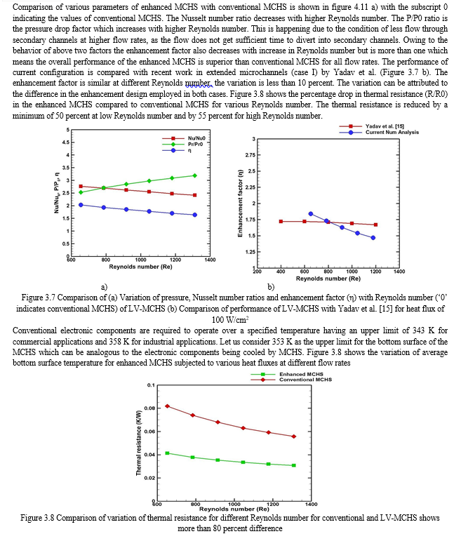
The bottom surface temperature is above the limit only for heat flux of 200 Watt per sq.cm. For the remaining heat fluxes, the bottom surface temperature is below the limit. Thus the enhanced LV- MCHS is suitable for heat flux of 150 Watt per sq.cm and also for heat flux of 200 Watt per sq.cm but using higher flow rates.
Conclusion
The main aim of this research was to develop new enhancement techniques in conventional MCHS which will increase their heat removing capability. Three dimensional computational models based on finite volume approach were created incorporating the enhancement techniques and analysed numerically in ANSYS WORKBENCH. Each computational model is checked for grid independence during meshing and the numerical results are validated with theoretical results and also with earlier research. The three designs have different geometry and different enhancement techniques. Hence, they are compared with respect to the enhancement over their respective conventional domain. Comparison of numerical results between three designs shows that the enhanced LV-MCHS has highest enhancement in Nusselt number (Nu/Nu0) but also has highest pressure drop ratio (Pr/Pr0). LP-MCHS has the lowest Nu/Nu0 and lowest Pr/Pr0. For a limiting surface temperature of 85°C, LV-MCHS handles the highest heat flux of 200 W/cm2.
References
[1] D. B. Tuckerman and R. F. W. Pease, “High-performance heat sinking for {VLSI},” {IEEE} Electron Device Lett., vol. 2, no. 5, pp. 126–129, May 1981. [2] M. Steinke and S. Kandlikar, “Review of single-phase heat transfer enhancement techniques for application in microchannels, minichannels and microdevices,” Int. J. Heat Technol., vol. 22, pp. 3–11, 2004. [3] R. J. Phillips, “Forced-convection, Liquid-cooled, Microchannel Heat Sinks,” Mech. Eng., vol. M.S., 1987. [4] M. Coyaud, C. Schaeffer, J. Boussey, and C. Perret, “Analytic modeling, optimization, and realization of cooling devices in silicon technology,” IEEE Trans. Components Packag. Technol., vol. 23, no. 4, pp. 665–672, 2000. [5] W. Qu and I. Mudawar, “Experimental and numerical study of pressure drop and heat transfer in a single-phase micro-channel heat sink,” Int. J. Heat Mass Transf., vol. 45, no. 12, pp. 2549–2565, 2002. [6] F. Mei, P. R. Parida, J. Jiang, W. J. Meng, and S. V. Ekkad, “Fabrication, assembly, and testing of Cu- and Al-based microchannel heat exchangers,” J. Microelectromechanical Syst., vol. 17, no. 4, pp. 869–881, 2008. [7] S. G. Kandlikar and W. J. Grande, “Evolution of Microchannel Flow Passages-- Thermohydraulic Performance and Fabrication Technology,” Heat Transf. Eng., vol. 24, no. 1, pp. 3–17, 2003. [8] P. S. Lee, S. V. Garimella, and D. Liu, “Investigation of heat transfer in rectangular microchannels,” Int. J. Heat Mass Transf., vol. 48, no. 9, pp. 1688–1704, 2005. [9] S. V. Garimella, V. Singhal, and D. Liu, “On-chip thermal management with microchannel heat sinks and integrated micropumps,” Proc. IEEE, vol. 94, no. 8, pp. 1534–1548, 2006. [10] W. Qu, I. Mudawar, S.-Y. Lee, and S. T. Wereley, “Experimental and Computational Investigation of Flow Development and Pressure Drop in a Rectangular Micro-channel,”J. Electron. Packag., vol. 128, no. 1, p. 1, 2006. [11] A. Ko?ar, “Effect of substrate thickness and material on heat transfer in microchannel heat sinks,” Int. J. Therm. Sci., vol. 49, no. 4, pp. 635–642, 2010. [12] A. Husain and K.-Y. Kim, “Thermal Optimization of a Microchannel Heat Sink With Trapezoidal Cross Section,” J. Electron. Packag., vol. 131, no. 2, p. 21005, 2009. [13] S. G. Kandlikar et al., “Heat Transfer in Microchannels{\\\\textemdash}2012 Status and Research Needs,” J. Heat Transfer, vol. 135, no. 9, p. 91001, Jul. 2013. [14] V. Yadav, K. Baghel, R. Kumar, and S. T. Kadam, “Numerical investigation of heat transfer in extended surface microchannels,” Int. J. Heat Mass Transf., vol. 93, pp. 612– 622, Feb. 2016. [15] A. Kosar and Y. Peles, “Thermal-Hydraulic Performance of {MEMS}-based Pin Fin Heat Sink,” J. Heat Transfer, vol. 128, no. 2, p. 121, 2006. [16] E. G. Colgan et al., “A Practical Implementation of Silicon Microchannel Coolers for High Power Chips,” {IEEE} Trans. Components Packag. Technol., vol. 30, no. 2, pp. 218–225, Jun. 2007. [17] F. Hong and P. Cheng, “Three dimensional numerical analyses and optimization of offset strip-fin microchannel heat sinks,” Int. Commun. Heat Mass Transf., vol. 36, no. 7, pp. 651–656, Aug. 2009. [18] H. Shafeie, O. Abouali, K. Jafarpur, and G. Ahmadi, “Numerical study of heat transfer performance of single-phase heat sinks with micro pin-fin structures,” Appl. Therm. Eng., vol. 58, no. 1–2, pp. 68–76, Sep. 2013. [19] Y. Jia, G. Xia, Y. Li, D. Ma, and B. Cai, “Heat transfer and fluid flow characteristics of combined microchannel with cone-shaped micro pin fins,” Int. Commun. Heat Mass Transf., vol. 92, pp. 78–89, Mar. 2018. [20] O. O. Adewumi, T. Bello-Ochende, and J. P. Meyer, “Constructal design of combined microchannel and micro pin fins for electronic cooling,” Int. J. Heat Mass Transf., vol. 66, pp. 315–323, Nov. 2013.
Copyright
Copyright © 2024 Kasukurthi Vardhan, C. Naga Bhaskar, S Venkateswara Rao. This is an open access article distributed under the Creative Commons Attribution License, which permits unrestricted use, distribution, and reproduction in any medium, provided the original work is properly cited.

Download Paper
Paper Id : IJRASET63895
Publish Date : 2024-08-06
ISSN : 2321-9653
Publisher Name : IJRASET
DOI Link : Click Here
 Submit Paper Online

