Ijraset Journal For Research in Applied Science and Engineering Technology
- Home / Ijraset
- On This Page
- Abstract
- Introduction
- Conclusion
- References
- Copyright
Advancements in Friction Stir Welding Techniques for Enhanced Performance in Aluminum Alloy Structures
Authors: Dasari Raja Rajeswari, Y. Rameswara Reddy
DOI Link: https://doi.org/10.22214/ijraset.2024.60565
Certificate: View Certificate
Abstract
Friction Stir Welding (FSW) is a solid- state welding method that can be utilized on both comparable and dissimilar materials. The technology is frequently utilized because it generates quality welds and avoids common issues like solidification and liquefaction cracks that are connected with fusion welding processes. The FSW of Aluminum 5086 and its alloys has been commercialized, and there is renewed interest in connecting dissimilar materials. However, before the process can be commercialized, research studies must be conducted to describe and set process windows. In particular, FSW has prompted researchers to try combining incompatible materials with different characteristics, such as Aluminum 5086, and sound welds with no or few intermetallic compounds have been formed. This paper reviews the present research on FSW between Aluminum 5086, including weld microstructure, mechanical testing, and production methods. Future research in this topic is also discussed. This project aims to maintain a rotational speed (rpm) of 850-1300. Welding speed (mm/min): 7.0–7.5. NASA uses friction stir welding to combine materials that are different or the same..
Introduction
I. INTRODUCTION TO FRICTION STIR WELDING
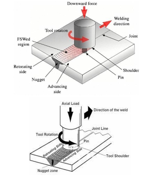
FRICTION STIR WELDING (FSW) was invented at The Welding Institute (TWI) of UK in 1991 as a solid–state joining technique, and was initially applied to aluminum alloys. In essence, FSW is very simple, although a brief consideration of the process reveals many subtleties. A rotating tool is pressed against the surface of two abutting or overlapping plates. The side of the weld for which the rotating tool moves in the same direction as the traversing direction, is commonly known as the advancing side and the other side, where tool rotation opposes the traversing direction, is known as the retreating side. An important feature of the tool is a probe (pin) which protrudes from the base of the tool (the shoulder), and is of a length only marginally less than the thickness of the plate. Frictional heat is generated, principally due to the high normal pressure and shearing action of the shoulder. Friction stir welding can be thought of as a process of constrained extrusion under the action of the tool. The frictional heating causes a softened zone of material to form around the probe. This softened material cannot escape as it is constrained by the tool shoulder. As the tool is traversed along the joint line, material is swept around the tool probe between the retreating side of the tool (where the local motion due to rotation opposes the forward motion) and the surrounding undeformed material. The extruded material is deposited to form a solid phase joint behind the tool. The process is by definition asymmetrical, as most of the deformed material is extruded past the retreating side of the tool.
II. DEFINITION
Friction Stir Welding is considered to be the most significant development in metal joining in a decade. In Friction Stir Welding no cover gas or flux is used, thereby making the process environmentally friendly, energy efficiency and versatility or it is a green technology?. The joining does not involve any use of filler metal and therefore any aluminum alloy can be joined without concern for the compatibility of composition, which is an issue in fusion welding. In FSW no cover gas or flux is used, and does not involve any use of filler metal so that the properties of the joints are improve compare to the parent metal. Friction stir welding can be applied to various types of joints like butt joints, lap joints, T butt joints, pipes and fillet joints with different thickness and different profile. FSW technique was initially developed for Al-alloys, it also has great potential for welding of Mg-, Cu-, Ti-, Al- alloy matrix composites, lead, some steels, stainless steels, and different material combinations, particularly those with close melting temperatures and similar behavior such as hot workability. However, cost effective stirring tools are needed for welding some of these materials such as metal matrix composites and those with high melting temperatures, i.e. steels and titanium alloys.
In this process, a specially consider important parameters, tool material, tool design, tool rotation, downward force and weld speed along the joint line, generating frictional heating that softens a material underneath the tool. The softened material flows around the tool through extensive plastic deformation and is consolidated behind the tool to form a solid-state continuous joint.
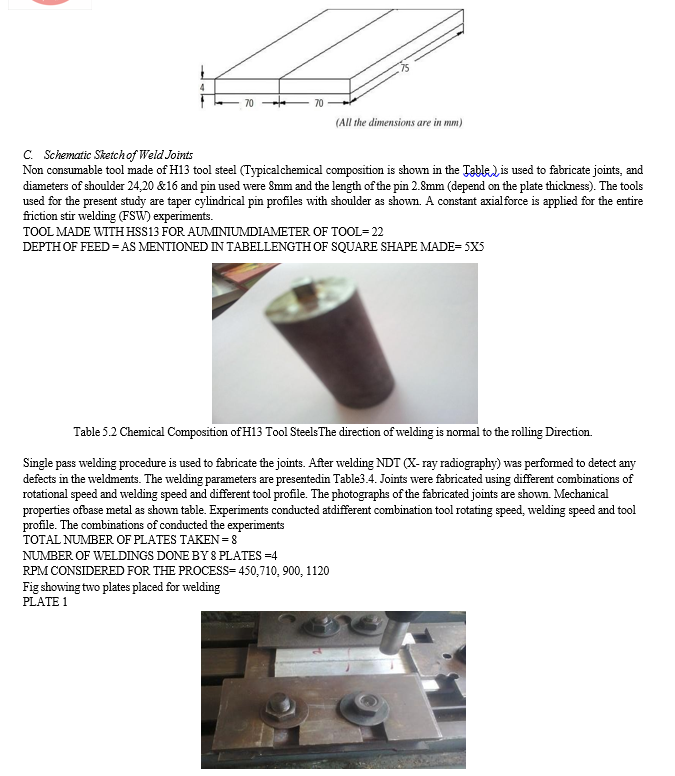
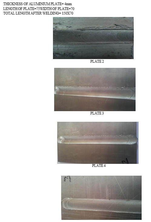
The plates are positioned in the fixture, which is prepared for fabricating FSW joints by using mechanical clamps so that the plate will not be separated during welding illustrated. The tool is fixed in the tool holder of the milling machine and the milling head is tilted with a rake angle of 00 to 30 to the vertical axis. The tool speed can be selected in the range between 710 to 1800 rpm based on the plate material and it thickness to be welded. Tool is lowered while in rotation and plunged in to the plates when the shoulder touches the plate, heat is generated. After a few second, table movement is given and it can be varied from 16 to 800 mm/min. This paper design of two newly developed tools which were used in the present work is illustrated in Figure. It should be noted that, in each design shape and size is same and having shoulder under surface is flat surface. The shoulder diameter is 18mm. The shoulder area in contact with work piece surface is same in all two cases. Two same shapes of the pin which were used flat shoulder profile with threaded pin. It should be noted that length of the pin is different in each case while surface area of the pin in contact with abutting base metal plates are different & depends upon pin length. For welding purpose Universal Milling Machine is used. Trial runs were conducted prior to conducting actual experiments. Other process parameter like mechanical performance of the welding, tensile strength is measured and the calculated value compared with the base material.
A. Methodology of FSW Process
In this process, a cylindrical-shouldered tool with a profiled threaded/unthreaded pin is rotated at a constant speed and fed at a constant traverse rate into the joint line between two pieces of plate material, which are butted together. The parts to be clamped rigidly onto a backing bar in a manner that prevents the abutting joint faces from being forced apart. The length of the pin is slightly less than the weld depth required and the tool shoulder should be in intimate contact with the work piece surface. The pin is then moved against the work piece or vice-versa. Frictional heat is generated between the wear resistant welding tool shoulder and pin, and the material of the work pieces. This heat along with the heat generated by the mechanical mixing process and the adiabatic heat with in the material, cause the stirred materials to soften without reaching the melting point.
As the pin is moved in the direction of welding the leading face of the pin, assisted by a special pin profile, forces plasticized material to the back of the pin whilst applying a substantial forging force to consolidate the weld metal. The welding of the material is facilitated by severe plastic deformation in the solid state involving dynamic recrystallization of the base material. The welded joints will be sliced using power hacksaw and then machined to required dimensions, American Society for Testing of Materials (ASTM E8M-04) guidelines should be followed for preparing the test specimens.
B. Process Parameters
FSW involves intricate material movement and plastic deformation. The tool geometry and welding parameters exert a significant effect on the microstructural evolution of the material.
Table I presents a brief summary of the grain size values for different aluminum alloys.
|
RPM |
FEED |
|
710 |
50 |
|
900 |
63 |
|
1120 |
100 |
|
1400 |
136 |
III. FRICTION STIR WELDING PROCESS
A. Flow Mechanisms and Tool Design
The metal flow and heat generation in the softened material around the tool are fundamental to the friction stir process. Material deformation generates and redistributes heat, producing the temperature field in the weld. But since the material flow stress is temperature and strain rate sensitive, the distribution of heat is itself governed by the deformation and temperature fields. In fact their control lies at the core of almost all aspects of FSW, for example, the optimisation of process speeds and machine loading, the avoidance of macroscopic defects, the evolution of the microstructure, and the resulting weld properties.
As noted above, almost all the material in the weld is extruded between the rotating pin on the retreating side and the surrounding material which is too cold and too lightly stressed to deform (see Fig.1). In its simplest form, this essential flow mechanism can be illustrated by two-dimensional simulations depicting streamlines round a rotating tool placed in a steady flow of material. Figure 3a shows streamlines past a cylindrical tool, redicted by computational fluid dynamics (CFD). A longitudinal weld seam is formed behind the advancing edge of the tool where the two flows come together.
Further modelling studies have investigated how this two-dimensional flow is perturbed by: the addition of tool features such as flats and flutes changes in the contact conditions between tool and workpiece, from sticking friction to slipping at a lower interfacial shear stress.
Predicted streamlines round a fluted tool are shown in b and c. Complete sticking generates a dead metal zone round the tool, whereas the flow interacts closely with the tool features when slipping takes place. Another characteristic of the process - a line initially perpendicular to the welding direction is swept into a backwards 'bulge' in the wake of the tool - can also be seen in Fig.3b and c. Marker experiments have confirmed this behaviour. One way of quantifying the mixing effect of the tool is the ratio of the swept volume to the pin volume. For 25mm thick plates this has found to be 1⋅1 : 1 for a cylindrical pin, 1⋅8 : 1 for the Whorl and 2⋅6 : 1 for the MX-Triflute pin, each having similar root diameters and lengths with the Triflute giving the more parallel sided weld zone. Further refinements include the Trivex tool which was designed to reduce the down and traverse forces required and the Triflat tool for thicker section materials
B. Experimental Procedure
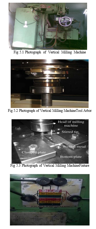
The experimental study includes the butt joining of 3 mm pure aluminum plates. The welding process is carried out on a vertical milling machine (Make HMT FM-2, 10hp, 3000rpm) as shown in Fig 5.1. Tool is hold in tool arbor as shown in Fig 5.2. Special welding jigs and fixtures are designed to hold two plates of 200 mm X 60 mm X 3 mm thickness as shown in fig 5.5.1. Table 5.1 shows the combinations of the tool rotational speed (RPM), welding speed (mm/min) and tool geometry and diameter of the tool shoulder to the diameter of the tool pin (Ds/Dp). These combinations are chosen based on the literature survey and the capability of the milling machine used for the experimental study. The schematic diagrams of tools used in this process are shown in Fig 5.5.2.

D. Advantages / Disadvantages of FSW for Aluminium Joining
The advantages of FSW for welding aluminium can be summarized as follows: as a solid state process it can be applied to all the major aluminium alloys and avoids problems of hot cracking, porosity, element loss, etc. common to aluminium fusion welding processes as a mechanised process, FSW does not rely on specialised welding skills; indeed manual intervention is seldom required no shielding gas or filler wire is required for aluminium alloys the process is remarkably tolerant to poor quality edge preparation: gaps of up to 20% of plate thickness can be tolerated, although this leads inevitably to a reduction in local section thickness since no filler is added the absence of fusion removes much of the thermal contraction associated with solidification and cooling, leading to significant reductions in distortion; however, it is not a zero distortion technique it is very flexible, being applied to joining in one, two and three dimensions, being applicable to butt, lap and spot weld geometries; welding can be conducted in any position excellent mechanical properties, competing strongly with welds made by other processes (see the section on 'Comparison with other joining processes') workplace friendly: there are no ultraviolet or electromagnetic radiation hazards as the absence of an arc removes these hazards from the process; the process is no noisier than a milling machine of similar power, and generates virtually zero spatter, fume and other pollutants the energy required at the weld for FSW lies between laser welding (which requires less energy) and metal inert gas (MIG) welding (which typically needs more) high welding speeds and joint completion rates: in single pass welds in thinner materials (down to 0?5 mm thickness), FSW competes on reasonable terms with fusion processes in terms of welding speed; in thicker materials, FSW can be accomplished in a single pass, whereas other processes need multiple passes. This leads to higher joint completion rates for FSW, even though the welding speeds may be lower. Thick plates can also be joined by FSW on either side various mechanical and thermal tensioning strategies can be applied during welding to engineer the state of residual stress in the weld (see the section on 'Residual stress control').

V. RESULT
- Aluminum is the best metal for friction stir welding process it gives better results when compared with different rpm and feed and as we increase the rpm the welding output is getting better.
- Tool profile used here is square of 5X5mm
- Strength of tool made is 50
- Materials used for making tool is H13
Conclusion
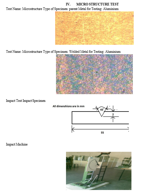
By conducting above experiment we can conclude that aluminium has the best properties for the process of friction stir welding. In this project we had undergone different rpm and feed for the aluminium and conducted several test like micro structure test, tensile test, etc. by observing all welding metals and process aluminium gives the better output. Aluminium in this process gives the better output of withstanding different conditions Welding of aluminium in friction stir welding process successfully obtained for different welding speeds, rotation speeds and different profiles. The following results were obtained. 1) At 1400 rpm tool rotates speed and 40/40mm/min traverse speed with square profile resulted in good mechanical properties. Joint efficiency is good 2) All fsw joints were failed at the retreating side this may be due to improper heat distribution at rending side. 3) In the welding of aluminium is not done done at 900 rpm tool rotates with a speed of 40mm/min of welding lack of heat generation. 4) Hardness variation is observing along cross-section of the welds it was observed that lowest hardness at retreating and beadt wen fusion zone and thermo mechanical affected zone. 5) By observing all speeds we can say that aluminium is giving better output.
References
[1] W.M. Thomas, I.M. Norris, D.G. Staines and E.R. Watts Friction Stir Welding – Process Developments and Variant Techniques. Paper presented at SME Summit, Oconomowoc Milwaukee USA Aug 3rd – 4th 2005. [2] Friction Stir Welding – An Update on Recent Developments. W.M. Thomas, S.A. Lockyer, S.W. Kalee and D.G. Staines. From a paper presented at ImechE Stressed Components in Aluminium Alloys 2nd April 2003. Birmingham UK. [3] K. R. Suresh, H. B. Niranjan, P. Martin Jebaraj and M. P. Chowdiah \" Tensile and Wear properties of Aluminium Composites\" Wear, 255 (2003), pp 638-642. [4] Majid Hoseini and Mohamood Mertian \"Tensile Properties of in-situ Aluminium- Alumina Composites\" Materials Letters 59 (2005), pp 3414-3418. [5] L. Ceschini, G. Minak and A. Morri \"Tensile and Fatigue properties of the AA6061/20 vol.% Al2O3 and AA7005/10 vol.% A12O3p Composites\" Composites Science and Technology 66 (2006), pp 333- 342. [6] Miroslav M. Mijajlovi, Nenad T. Pavlovi “Experimental studies of parameters affecting the heat generation in friction stir welding process” thermal science, Year 2012, Vol. 16, Suppl. 2, pp. S405-S417. [7] Moataz M. Attallaha, Hanadi, G. Salemb, “Friction stir welding parameters: a tool for controlling abnormal grain growth during subsequent heat treatment Materials Science and Engineering A 391 (2005) 51–59. [8] P. Bahemmat, A. Rahbari “Experimental study on the effect of rotational speed and tool pin profile on aa2024 aluminium friction stir welded butt joints” 2008 ASME Early Career Technical Conference October 3-4, 2008, Miami, Florida, USA. [9] Indira Rani M., Marpu R. N. and A. C. S. Kumar “A study of process parameters of friction stir welded AA 6061 aluminum alloy in o and t6 conditions ARPN Journal of Engineering and Applied Sciences VOL. 6, NO. 2, February 2011. [10] R.S. Mishraa, Z.Y. Mab “Friction stir welding and processing” Materials Science and Engineering R 50 (2005) 1–78. [11] Ahmed Khalid Hussain, Syed Azam Pasha Quadri “Evaluation of parameters of friction stir welding for aluminium AA6351 alloy International Journal of Engineering Science and Technology Vol. 2(10), 2010, 5977-5984. [12] R. Rai1, A. De, H. K. D. H. Bhadeshia and [13] T. DebRoy “Review: friction stir welding tools” Science and Technology of Welding and Joining 2011 VOL 16 NO 4. [14] Moataz M. Attallaha, Hanadi G. Salemb, “Friction stir welding parameters: a tool for controlling abnormal grain growth during subsequent heat treatment” Materials Science and Engineering A 391 (2005) 51–59. [15] S. Mandal, J. Rice, A.A. Elmustafa “Experimental and numerical investigation of the plunge stage in friction stir welding” journal of materials processing technology 2 0 3 ( 2 0 0 8 ) 411–419. [16] K. Kumar, Satish V. Kailas “The role of friction stir welding tool on material flow and weld formation Materials” Science and Engineering A 485 (2008) 367–374. [17] H. K. D. H. Bhadeshia and T. DebRoy “Critical assessment: friction stir welding of steels” Science and Technology of Welding and Joining 2009 VOL 14 NO 3.
Copyright
Copyright © 2024 Dasari Raja Rajeswari, Y. Rameswara Reddy. This is an open access article distributed under the Creative Commons Attribution License, which permits unrestricted use, distribution, and reproduction in any medium, provided the original work is properly cited.

Download Paper
Paper Id : IJRASET60565
Publish Date : 2024-04-18
ISSN : 2321-9653
Publisher Name : IJRASET
DOI Link : Click Here
 Submit Paper Online

