Ijraset Journal For Research in Applied Science and Engineering Technology
- Home / Ijraset
- On This Page
- Abstract
- Introduction
- Conclusion
- References
- Copyright
The Fundamental of Fiber Bragg Grating (FBG) Sensor
Authors: Muhammad Arif Bin Jalil
DOI Link: https://doi.org/10.22214/ijraset.2024.64038
Certificate: View Certificate
Abstract
An optical sensor known as an FBG is produced by laterally exposing a single mode fiber core to a strong UV laser light pattern on a regular basis. The exposure causes a sustained increase in the refractive index (ncore) of the fiber\'s core, resulting in fixed index modulation called grating (?). The grating inside the fiber optic core must reflect a certain wavelength of incoming light while transmitting all other wavelengths. This wavelength is referred to as the Bragg wavelength or Bragg linked to grating period. FBG functions as intended when a Bragg reflector is built on an optical fiber by taking use of the regular fluctuations in the refractive index of the single mode fiber core. When light travels through the FBG, certain wavelengths will be transmitted and others will be reflected. When the strain or temperature around the grating varies, a shift in the wavelength of the light reflected is observed.
Introduction
I. INTRODUCTION
Fibre Bragg Grating (FBG) have shown a great potential advantage in biomedical application over the past ten years [1] due to their prominent characteristics, which include their extremely small size, light weight, immunity to electromagnetic interference (EMI), electrical neutrality, and ability to be easily embedded into a structure without having any effects on the mechanical properties of the object under investigation[2][3].Fibre Bragg Grating was used as a photoacoustic (PA)detection method to detect the presence of malignancies because of its capacity to transform the absorbed energy entirely into heat without producing PA signals caused by scattering particles[4]. Because it combines light contrast and ultrasonic resolution, the photoacoustic approach is unique[5]. Due to its advantages of being noninvasive, having a high detection sensitivity, and being able to detect small element size, this approach is employed in the detection of tumors[6],[7].
A sensor can be made out of specifically constructed optical fiber. In a tiny portion of the fiber, the core refractive index of the optical fiber intended for sensor applications differs from that of the normal fiber core and cladding [8]. Usually, a periodic structure is introduced in that tiny portion of the optical fiber core. Fibre Bragg Gratings (FBG) are the name given to this region of the fiber core because it reflects specific wavelengths of light. When a dielectric waveguide's properties are regularly altered, the effective refractive index of the guide is also periodically altered [9],[10]. Alternatively, when a DBR is a structure composed of multiple, alternating layers of materials with variable refractive indices. FBG-based sensors are those whose sensitivity is determined by the Bragg wavelength shift of Fibre Bragg Gratings. The FBG is a periodic wavelength scale modification of the refractive index that is encoded in the fibre core segment. The light at a specific wavelength that satisfies the Bragg condition is reflected by Bragg gratings. When forward and back propagation modes at a particular wavelength couple, this reflection in a grating happens [11]. When the particular requirement e.g Bragg condition between the light wave vectors and the grating's vector number is met, the coupling coefficient of the modes is at its maximum:
(1)
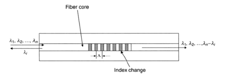
the grating period, the effective refractive index of the core, the effective wavelength of light known as the Bragg wavelength, and the diffraction order m. Figure 1 depicts the fibre Bragg grating's operating principle.
For a single FBG, there are theoretically an infinite number of Bragg wavelengths. The diffraction order Bragg wavelength changes for different values of m, as may be inferred from equation (1). In actuality, only one or occasionally two Bragg resonance wavelengths are used because there is a large spectral gap between the two. The second Bragg wavelength of the grating will be twice as short, at 750 nm, assuming the first one, m=1550 nm, is 1550 nm. However, the spectral range of the sources utilized for fiber is usually limited to 100 nm.
Additional Bragg peaks may show up if the refractive index modulation in FBG is not sinusoidal, as it usually is. For instance, the Fourier spectrum of a rectangular grating includes many modulation frequencies, which can lead to a number of Bragg peaks. Despite the fact that the majority of fiber-based gratings have essentially sinusoidal index modulation. There are several FBG structures; however, in this study, a uniform FBG was used for the experiment and analysis to examine how well an FBG functions as a sensor.
II. THE FUNDAMENTALS OF FBG SENSING PRINCIPLE
According to figure 1, the Fibre Bragg Grating (FBG) is a single mode fibre with a periodic refractive index , n modulation along its core. A fixed index modulation known as a grating is produced when a single mode optical fibre is exposed to strong UV radiation, which increases the reflective index of the fibre core[9]. The Bragg's wavelength which is the maximum reflectivity is the wavelength that is reflected when the FBG is exposed to a specific wavelength since the grating area's period is roughly half that of the input light's wavelength, as indicated in equation (2) [1][3][8].
(2)
Where neff is the effective refractive index of the fibre core, Λ is the FBG period, and λB is the Bragg grating wavelength in the free-space centre wavelength of the input light that will be back-reflected from the FBG. The fibre also transmits the other portion of the light.

Figure 1: Schematic diagram of a fiber Bragg grating. [14]
Two quantities in (1), namely temperature and strain, are susceptible to changes in external conditions.Effective index of the core ,neff and grating period Λ are these parameters. When the temperature varies, the thermo-optic effect causes the effective index to change, whilst the glass's thermal expansion causes the period to vary. When strain is applied, effective index changes as a result of the elasto-optic effect, whereas period changes as a result of the glass's elasticity, both of which are explained by Hooke's law. The overall Bragg wavelength will change by λB as a result of the effective index and period of the grating shifting as a result of strain and temperature changes. Therefore, the Bragg condition will produce an equation (3):
(3)
Since the final part of the formula represents the multiplication of two little amounts, it can be ignored. We shall arrive at the formula for the change of Bragg wavelength after including accounting for (1):
(4)
The Bragg wavelength will change if any of the aforementioned parameters changes. One can detect the change by comparing the associated Bragg wavelength shift with the reference.
III. REFLECTION AND TRANSMISSION OF LIGHT IN FIBER BRAGG GRATING
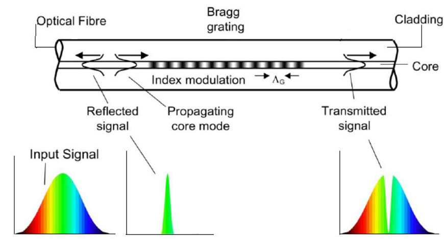
The refractive index of the fibre core is varied with a period of as seen in the above figure. The portion of light whose wavelength matches the wavelength of the fibre Bragg grating will be reflected back to the input end when a light source with a broad spectrum is fired into one end of the fibre, while the remaining light will flow through to the other end. The following diagram explains this reflection phenomenon.

Figure 2 : The reflection and Transmission Spectrum of an FBG. [15]
The following equation can be derived from the Bragg grating condition's requirement for momentum conservation:
(5)
where λB is the wavelength of the light reflected by the Bragg grating and neff is the effective refractive index of the fibre core.
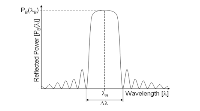
Fresnel reflection is the fundamental idea that drives fibre Bragg grating (FBG) operation. When light can reflect and refract at the interface of two media with different refractive indices. Over a predetermined length, the fibre Bragg grating will normally exhibit a sinusoidal refractive index fluctuation. As illustrated in Figure 3, the bandwidth, or the distance in wavelengths between the initial minima, is determined by Δλ where δn0 is the variation in the refractive index (n3-n2), and η is the fraction of power in the core.
(6)

Figure 3: The graph of Reflected Power versus wavelength of a Fiber Bragg Grating. [14]
IV. WORKING PRINCIPLE OF FIBER BRAGG GRATING
A single mode fibre core is laterally exposed to a periodic pattern of powerful UV laser light to create an optical sensor called an FBG. The exposure results in a long-lasting rise in the fiber's core's refractive index (), producing fixed index modulation known as grating (). The grating inside the fibre optic core must transmit all other light, as indicated in the picture below, while reflecting a specific wavelength of input light known as the Bragg wavelength (Bragg related to grating period). Equation provides the Bragg wavelength.
(7)
When a change in physical qualities takes place and is determined by equation, an interrogation unit, as illustrated in the above figure, is used to detect the shift in the reflected Bragg wavelength.
(8)
When pe is the strain-optic coefficient, T is the change in temperature, induced strain, thermal expansion coefficient, and thermo-optic coefficient are all present. According to the equation above, temperature and strain both affect Bragg shift. Pe = 0.22 and various coefficients are known for silica fibre.
V. FBG EQUATIONS FOR TEMPERATURE MEASUREMENT
The equation below provides the shift in the peak of the Bragg wavelength.
(9)
(10)
For fused Silica,
(11)
(12)
Bragg wavelength sensitivity to temperature,
(13)
VI. FBG EQUATIONS FOR STRAIN MEASUREMENT
A sensor's length, or strain, L, varies from its initial length when stress is applied to it. L/L is the equivalent strain over an applied stress to the fiber. Temperature adjustment is required because thermal expansion causes temperature to affect physical dimensions. Strain alone cannot be measured with an FBG sensor unless the impact of temperature on wavelength shift calculations is taken into account. To counterbalance the effect of local temperature on the FBG, this can be achieved by putting a temperature sensor along it. Therefore, we have subtracted eq. (10) from eq. (9) to yield eq. (5) below in order to measure strain.
Equation gives the wavelength shift proportional to the applied strain.
(14)
(15)
where p is the effective strain-optic constant, denoted as where e is the applied axial strain.
(16)
where v is the Poisson's ratio and p1 and p2 are parts of the strain-optic sensor. P1 = 0.113, P2= 0.252, V = 0.16, and N = 1.482 for a germanosilicate optical fibre. As a result, p has the value 0.22.
Bragg wavelength sensitivity to strain,
(17)
Conclusion
In the electrical and electronics sectors, an electronic sensor may malfunction in an environment with high voltage and electromagnetic interference. It is nearly impossible for a typical sensor to measure in these conditions. A good way to address this problem is to measure the parameters using an FBG sensor that is integrated into an optical fiber. Fiber bragg grating (FBG) sensors are multiplexed, lightweight, easy to install, and can sense various parameters at different points along a single sensor line, such as temperature, strain, load, and pressure. Conventional sensors need electricity to work. Optical fibre sensors don\'t require a power source to be put passively over hundreds of kilometers on transmission lines, gas pipelines, etc. because they are inert.
References
[1] E. Al-Fakih, N. A. Abu Osman, and F. R. Mahamd Adikan, “The Use of Fiber Bragg Grating Sensors in Biomechanics and Rehabilitation Applications: The State-of-the-Art and Ongoing Research Topics,” Sensors, vol. 12, no. 12, pp. 12890–12926, 2012. [2] T. Fink, Q. Zhang, W. Ahrens, and M. Han, “Study of ?-phase-shifted, fiber Bragg gratings for ultrasonic detection,” Fiber Opt. Sensors Appl. IX, vol. 8370, no. 7, pp. 1–7, 2012. [3] G. Wild and S. Hinckley, “Optical Fibre Bragg Gratings for Acoustic Sensors,” Int. Congr. Acoust., no. August, pp. 1–7, 2010. [4] A. Yarai and T. Nakanishi, “Fiber Bragg grating applied pulsed photoacoustic detection technique for online monitoring concentration of liquid,” J. Acoust. Soc. Am., vol. 123, no. 5, p. 3285, 2008. [5] C. Li and L. V Wang, “Photoacoustic tomography and sensing in biomedicine,” Phys. Med. Biol., vol. 54, no. 19, pp. R59–R97, 2009. [6] M. Xu and L. V. Wang, “Photoacoustic imaging in biomedicine,” Rev. Sci. Instrum., vol. 77, no. 4, p. 041101, 2006. [7] J. Xia, J. Yao, and L. V Wang, “Photoacoustic Tomography?: Principles and Advances,” Prog. eletromagnic Res., vol. 147, no. May, pp. 1–22, 2014. [8] E.Udd, Fiber Optic Sensors: An Introduction for Engineerings and Scientists (John Wiley and Sons, New York, 1991). [9] A.Cusano, A. Cutolo and M. Giordano, “Fiber Bragg Gratings Evanescent Wave Sensors: A View Back and RecentAdvancements”, Sensors, Springer-Verlag Berlin Heidelberg, 2008. [10] K.O.Hill and G. Meltz, “Fiber Bragg Grating Technology Fundamentals and Overview”, Journal of Lightwave Technology, Vol. 15,No. 8, August 1997. [11] G.P. Agrawal, Fiber-Optic Communication Systems, (John Wiley & Sons, 2002). [12] P. Fomitchov and S. Krishnaswamy, “Response of a fiber Bragg grating ultrasonic sensor,” Opt. Eng., vol. 42, no. 4, pp. 956–963, 2003. [13] M. A. Othman, M. M. Ismail, H. A. Sulaiman, et.al., “An Analysis of 10 Gbits / s Optical Transmission System using Fiber Bragg Grating ( FBG ),” IOSR J. Eng., vol. 2, no. 7, pp. 55–61, 2012. [14] https://www.fiberoptics4sale.com/blogs/archive-posts/95046406-what-is-fiber-bragg-grating [15] https://tempsens.com/blog/fiber-bragg-grating-based-sensors
Copyright
Copyright © 2024 Muhammad Arif Bin Jalil. This is an open access article distributed under the Creative Commons Attribution License, which permits unrestricted use, distribution, and reproduction in any medium, provided the original work is properly cited.

Download Paper
Paper Id : IJRASET64038
Publish Date : 2024-08-21
ISSN : 2321-9653
Publisher Name : IJRASET
DOI Link : Click Here
 Submit Paper Online

