Ijraset Journal For Research in Applied Science and Engineering Technology
- Home / Ijraset
- On This Page
- Abstract
- Introduction
- Conclusion
- References
- Copyright
Implementing Failure Mode & Effect Analysis(FMEA) on Framework Structure
Authors: Mr. Suraj. D. Bhagat, Mr. Hrithik. N. Bichakule, Mr. Aniket. B. Mali, Mr. Yash. A. Patil, Ms. Anuradha. S. Waghmare, Prof. Ufaq. U. Buch
DOI Link: https://doi.org/10.22214/ijraset.2024.62712
Certificate: View Certificate
Abstract
The Failure modes and effects analysis (FMEA) is one of the most practical design tools implemented in the product design to analyze the possible failures and to improve the design. The use of FMEA is diversified, and different approaches are proposed by various organizations and researchers from one application to another. The question is how to use the features of FMEA along with the design process. This research focuses on different types of FMEA in the design process, which is considered as the mapping between customer requirements, design components, and product functions. These three elements of design are the foundation of the integration model proposed in this research. The objective of this research is to understand an integrated approach of FMEA in the design process. Significantly, an integration framework is developed to integrate the design process and FMEA. Then, a step-by-step FMEA-facilitated design process is proposed to apply FMEA along with the design process. The analysis should always be started by someone listing the functions that the design needs to fulfil. Functions are the starting point of a well done FMEA, and using functions as baseline provides the best yield of an FMEA. After all, a design is only one possible solution to perform functions that need to be fulfilled. This way an FMEA can be done on concept designs as well as detail designs, on hardware as well as software, and no matter how complex the design.
Introduction
I. INTRODUCTION
Failure Mode and Effect Analysis (FMEA) is a risk management tool to proactively identify and assess the causes and effects pf potential failures in a system, thereby preventing them from happening. FMEA is a powerful tool to improve your project feasibility and life of the project.
Every day, companies are submissive to several risks that may influence the good sequences of their activities. Therefore, risk management to be proved as a good management philosophy that can reduce or limits negative effects of risks.
Introducing Failure Mode and Effect Analysis (FMEA) into a framework structure involves integrating it as a systematic method for identifying and prioritizing potential failures in a system, assessing their effects, and developing strategies to mitigate or eliminate them. In a framework structure, FMEA can serve as a proactive tool to enhance reliability, safety, and performance by anticipating and addressing potential weaknesses or vulnerabilities. It helps in making informed decisions regarding risk management and optimization of processes within the framework.
Failure mode and effect analysis [FMEA] is a risk management tool to proactively identify and assess the causes and effects pf potential failures in a system, thereby preventing them from happening. FMEA is a powerful tool to improve project feasibility and life of the project.
FMEA provides a structured framework for evaluating the potential failure modes of beams and columns, assessing their effects on structural performance and safety, and prioritizing mitigation strategies to minimize risks. By systematically analysing failure modes and their potential consequences, engineers can identify vulnerabilities early in the design or maintenance phase and implement targeted measures to enhance structural reliability and resilience.
II. METHODOLOGY
A. Theory of FMEA
First Failure Mode and Effect Analysis [FMEA] is a risk management tool to proactively identify and assess the causes and effects pf potential failures in a system, thereby preventing them from happening. FMEA is a powerful tool to improve your project feasibility and life of the pr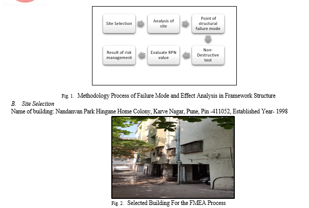 oject.
C. Analysis of Selected Site
- Location – (Geographical Location, Land use and zoning):
a. Geographical Location: Evaluate the site's geographical features such as topography, climate, and proximity to natural hazards (e.g., flood zones, seismic activity).
b. Land Use and Zoning: Assess the current and proposed land use regulations, zoning ordinances, and development plans governing the site. Consider compatibility with adjacent land uses, density restrictions, and environmental protection requirements
2. Infrastructure – (Demographics, Consideration):
a. Demographics: Analyze demographic data such as population density, age distribution, income levels, and employment rates in the surrounding area. This information provides insights into the potential customer base, workforce availability, and market demand.
b. Infrastructure Considerations: Evaluate the adequacy and condition of infrastructure facilities such as roads, utilities (water, sewer, electricity), telecommunications, and public services (schools, hospitals, emergency services). Consider the capacity to support existing and future development needs
3. Risk Factor
a. Identify and assess potential risks and hazards associated with the site, including natural disasters (e.g., floods, earthquakes, hurricanes), environmental contamination (e.g., soil or groundwater pollution), and man-made hazards (e.g., industrial accidents, terrorist threats).
b. Conduct a risk assessment to quantify the likelihood and consequences of these risks, and develop mitigation strategies to minimize their impact on the site and its occupants.
4. Stakeholder Analysis
a. Identify stakeholders who have an interest or influence in the site, including property owners, developers, government agencies, local residents, community organizations, and advocacy groups.
b. Analyze stakeholders' interests, concerns, and expectations regarding the site's development and operation. Consider their level of support or opposition, potential conflicts of interest, and opportunities for collaboration or engagement.
c. Develop a stakeholder engagement plan to communicate with and involve stakeholders throughout the planning, design, and implementation stages of the project, ensuring transparency, inclusivity, and accountability
5. Common Structural Failure Mode
a. Collapse: The structure loses its stability and collapses due to an inability to support the loads applied to it. This can occur suddenly and catastrophically.
b. Buckling: Buckling is a failure mode characterized by the sudden sideways deflection of a structural component, often due to compressive loads exceeding the critical limit
c. Shear Failure: Shear failure occurs when forces acting parallel to the plane of a material cause it to slide internally along that plane. This can result in the separation of structural elements.
d. Tensile Failure: Tensile failure happens when a material is subjected to excessive tensile (pulling or stretching) forces, causing it to rupture or break.
e. Fatigue Failure: Fatigue failure occurs over time due to repeated loading and unloading cycles, leading to the progressive weakening of the material and eventual failure, even under loads well below the material's ultimate strength.
f. Cracking: Cracking in concrete or other materials can be a precursor to failure. Cracks can form due to various factors, including overloading, settlement, or material deterioration.
g. Deformation: Excessive deformation or excessive movement beyond the structure's design limits can lead to failure. This can include excessive bending, twisting, or displacement.
h. Corrosion-Induced Failure: For structures made of materials like steel, corrosion can weaken the material and lead to structural failure over time.
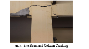
6. Selected Site Structural Issues:
a. Cracking in buildings:it crucial to identify potential failure modes, their causes, and the effects they can have on the structure, occupants, and operations. Here's how we can approach it:
The primary failure mode is cracking in structural or non-structural elements of the building. Cracks can occur in structural members like beams and columns.
The Main Cause of Cracking:
- Structural Overloading: Excessive loads or inadequate design can lead to stress concentrations and subsequent cracking in structural elements.
- Foundation Settlement: Differential settlement of the foundation due to soil movement or poor compaction can cause cracks in walls, floors, and other building elements
- Thermal or Moisture Movements: Fluctuations in temperature and moisture content can induce expansion and contraction in materials, leading to cracking over time.
- Material Defects or Incompatibility: Poor quality materials, improper mixing, or incompatible materials used in construction can result in weakened areas prone to cracking.
- Environmental Factors: Exposure to harsh weather conditions, seismic activity, or aggressive chemicals can accelerate the deterioration of building materials and promote cracking.
- Construction Practices: Inadequate reinforcement, improper curing, or improper installation techniques during construction can contribute to cracking
b. Potential Effect:
- Structural Integrity: Reduced load-bearing capacity, instability, or collapse.
- Water Intrusion and Damage: Moisture damage, Mold growth, and deterioration of finishes
- Aesthetic Concerns: Detract from visual appearance, affect value or marketability.
- Safety Hazards: Tripping hazards, especially in high-traffic areas.
- Operational Disruption: Necessitate repairs, causing disruption to occupants or business operations.
By systematically analysis the site potential failure mode of cracking in a building and its effects, stakeholders can prioritize actions to mitigate risks, enhance safety and structural integrity, and preserve the functionality and value of the building over time.
???????III. NON-DESTRUCTIVE TESTING
A. Rebound Hammer Test
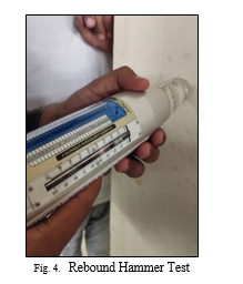
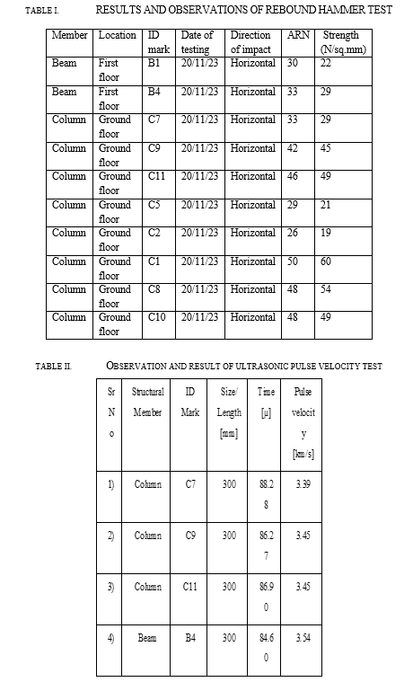
Rebound hammer test method is most useful and common non- destructive test performed on concrete. For checking the uniformity of concrete in laboratory as well as in the field. It works on the principle that the rebound of an elastic mass depends on the hardness of the surface against which the mass impinges. The rebound value indicated by the hammer is related empirically to the compressive strength of concrete. Rebound hammer are thus able to provide a quick estimate of the quality of concrete.
The rebound hammer test is a non-destructive method used to assess the compressive strength of concrete. Here is a basic procedure:
- Prepare the Surface: Ensure the surface of the concrete to be tested is clean and free from loose particles or dust
- Calibrate the Hammer: Before starting, calibrate the rebound hammer according to the manufacturer's instructions. This typically involves hitting a reference test anvil and adjusting the instrument to a specific value.
- Select Test Points: Decide on the locations where you'll conduct the tests. Typically, these points are chosen randomly to represent different areas of the concrete structure.
a. Perform the Test
- Hold the rebound hammer perpendicular to the surface of the concrete.
- Ensure the protective cap is in place to avoid damage to the hammer.
- Press the plunger against the concrete surface and release it. The rebound hammer will then strike the surface, and the rebound distance will be recorded by a scale on the hammer.
- Take several readings at each test point to ensure accuracy. Typically, 8 to 15 readings are taken per test point.
- Record Results: Record the rebound values obtained at each test point.
- Analysis Results: Compare the rebound values to a correlation chart provided by the manufacturer. This chart correlates rebound values to compressive strength.

B. ???Ultrasonic Pulse Velocity Test:
Ultrasonic pulse velocity test method is works on the principle that the velocity of pulse passing through any solid material is primarily dependent upon the density and the elastic properties of the material. Density and elastic properties of a material are related to the strength of the material.
The ultrasonic pulse velocity (UPV) test is a non-destructive technique used to assess the quality of concrete, the presence of cracks, voids, or other defects. Here a basic procedure:
- Preparation
- Ensure the concrete surface is clean and free from debris.
- Set up the testing equipment according to the manufacturer's instructions.
2. Calibration: Calibrate the equipment using a reference block of known thickness and material properties.
3. Coupling: Apply a thin layer of coupling agent (usually water or gel) to ensure good contact between the transducers and the concrete surface
4. Transducer Placement:
- Place one transducer (usually a transmitter) on the surface of the concrete at one end of the testing path.
- Place the other transducer (receiver) on the surface at the other end of the testing path, ensuring a straight line between them.
5. Testing:
- Trigger the equipment to send ultrasonic pulses from the transmitter to the receiver.
- Measure the time taken for the pulse to travel through the concrete.
- Repeat the test at multiple locations on the concrete surface, especially where defects are suspected.
C. Evaluate The RPN Processes
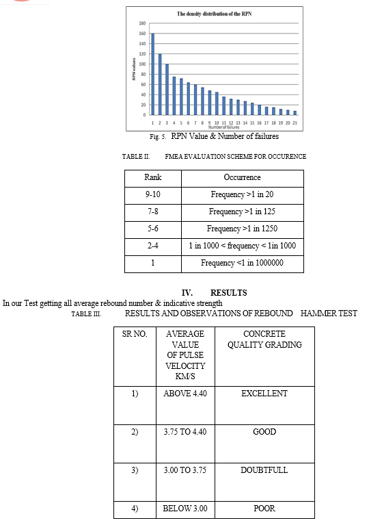
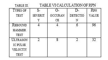
Risk Priority Number (RPN) is a numerical ranking of the risk on each possible failure mode, made up of the arithmetic product of the three elements: severity of the effect, the likelihood of occurrence of the cause, and the likelihood of detection of the cause
Definition of symbols:
- S = Severity ranking ( seriousness of something bad or unpleasant)
- = Occurrence ranking ( how frequently a particular failure mode is likely to occur)
- D = Detection ranking ( likelihood of detection of the failure mode/cause )
- RPN = (S x O x D)
 ???????
Conclusion
A Risk Priority Number (RPN) value of 96 falls within the low-risk category according to the typical thresholds used in many industries. This indicates that while there are identified risks associated with the analyzed process or system, they are relatively minor in severity, occurrence, and detection. In conclusion, the RPN value of 96 suggests that the identified risks, although present, do not pose an immediate threat to the integrity, safety, or functionality of the system. However, it is essential to remain vigilant and monitor these risks over time to ensure they do not escalate or compound into more significant issues. In conclusion, analysis for ultrasonic pulse velocity (UPV) the Risk Priority Number (RPN) 32 serves as a vital tool for assessing and managing risks inherent in the UPV testing process. Through systematic identification and quantification of potential risks, the RPN methodology offers a structured approach to prioritize areas requiring attention. By assigning severity, occurrence, and detection scores to each identified risk, the analysis enables stakeholders to focus on critical factors that could impact the reliability and accuracy of UPV measurements. Overall, while an RPN value of 96 & 32 indicates a relatively low level of risk, it underscores the importance of proactive risk management practices and ongoing vigilance to maintain the integrity and reliability of the system. In conclusion, the amalgamation of Failure Mode and Effects Analysis (FMEA) with rebound hammer and ultrasonic pulse velocity tests has provided a comprehensive framework for evaluating and prioritizing structural risks associated with concrete constructions. Through this holistic approach, we have gained valuable insights into potential failure modes, their effects, and the likelihood of occurrence, enabling informed decision-making to enhance structural integrity and safety. The utilization of rebound hammer and ultrasonic pulse velocity tests has facilitated the identification of critical parameters influencing the structural performance of concrete elements. These non-destructive testing methods have allowed us to assess the quality, homogeneity, and integrity of concrete, enabling early detection of defects and vulnerabilities
References
[1] Bashir Salah a, Mohammed Alnahhal b, Mujahid Ali “Risk prioritization using a modified FMEA analysis in industry 4.0” [2] Jianxin You, Shuqi Lou, Renjie Mao, Tao Xu. “An improved FMEA quality risk assessment framework for enterprise data assets” [3] Thu Ya Mon “Hazards identification & risks assessment for high-rise building construction by failure mode and effects analysis [FMEA] & prevented by OH&S management system.” [4] Mohammed Almarwae. “Structural Failure of Buildings: Issues and Challengs” [5] SHOU QING WANG et al “Risk Management Framework For Construction Project in Developing Countries” [6] Mahdi Bahrami, Danial Hadizadeh Bazzaz, S. Mojtaba Sajjadi “Innovation and Improvements In Project Implementation and Management; Using FMEA Technique” [7] Mohammed fadhil dulaimi, shou qing wang, Shou qing wang “Risk management framework for construction project in developing countries” [8] Olushola Akinshipe, Clinton Aigbavboa, Nokulunga Mashwama, Wellington Didibhuku Thwala “Failure of Construction Projects: Exploring the Impacts on the Society” [9] Hemant Gain, Anjay Kumar Mishra. “Risk Analysis in Road construction Using Failure Mode and Effect Analysis.” [10] Chandrasekhar Putcha, Subhrajit Dutta, Jessica Rodriguez. “Risk Priority Number for Bridge Failures.”
Copyright
Copyright © 2024 Mr. Suraj. D. Bhagat, Mr. Hrithik. N. Bichakule, Mr. Aniket. B. Mali, Mr. Yash. A. Patil, Ms. Anuradha. S. Waghmare, Prof. Ufaq. U. Buch. This is an open access article distributed under the Creative Commons Attribution License, which permits unrestricted use, distribution, and reproduction in any medium, provided the original work is properly cited.

Download Paper
Paper Id : IJRASET62712
Publish Date : 2024-05-25
ISSN : 2321-9653
Publisher Name : IJRASET
DOI Link : Click Here
 Submit Paper Online

