Ijraset Journal For Research in Applied Science and Engineering Technology
- Home / Ijraset
- On This Page
- Abstract
- Introduction
- Conclusion
- References
- Copyright
Analysis of Induction Based Wireless Power Transfer Scheme
Authors: Santosh Arcot
DOI Link: https://doi.org/10.22214/ijraset.2023.54635
Certificate: View Certificate
Abstract
Wireless power transfer scheme has become quite popular in recent times and used in various applications including consumer electronics, and electrical vehicle chargers. Although the power transfer scheme based on magnetic induction is knowledge, the relationship between efficiency of power transfer scheme with the ferrite core cross sectional area is not well understood. Surfaces with symmetrical ferrite core cross section area, will have good magnetic coupling while unsymmetrical cross-sectional surfaces with smaller overlap of magnetic flux, will suffer from high leakage inductance and excessive losses. Since majority of the wireless charging applications use non-uniform magnetic surfaces, the efficiency of real power transfer across primary and secondary windings tends to be lower and will require additional compensating circuitry or complex control algorithm. Unless a thorough understanding of leakage inductance is performed, wireless power topology will suffer from excessive resonant power circulation and output regulation will become unstable. Compensating circuit added at the secondary output can decrease overall reliability and increase BOM (Bill of material) cost. In this paper, wireless power transfer scheme is reviewed, and a theoretical model is provided. Analysis will be presented for various leakage inductances including the impact of operating frequency and line/load conditions.
Introduction
I. INTRODUCTION
The objective of this paper is to review wireless power transfer schemes and highlight the impact of leakage inductance due to varying cross-sectional area of magnetic material. Analysis is presented to analyse closely coupled magnetic assembly and contrast against non-uniform cross-sectional surfaces. As wireless power transfer mechanism is adopted into various applications starting from simple electronic chargers to electrical vehicles, it is important to understand various applications and differentiate wireless power transfer mechanisms adopted in each application. Efficiency of wireless power transfer scheme is severely impacted by the changing leakage inductances and additional regulating circuit may be needed to compensate for magnetic coupling loss between various ferrite core shapes. In this paper, analysis of magnetic coupling between two leakage inductance values is provided and methods to regulate output voltage are discussed. Mathematical model with analytical results is provided.
II. POWER TRANSFER TOPOLOGY AND LITERATURE SURVEY
Inductive wireless power transfer systems tend to be expensive, bulky and have physical limitations [3]. Dynamic wireless power transfer systems are particularly problematic as the magnetic path shifts both in time and distance. Two coils based wireless power transfer studies shows efficacy of power transmission is higher with symmetrical coils and for unsymmetrical shaped coils, largest transmission will ensure increased efficiency [1]. Magnetic flux distribution area of the ferrite determines the power transfer efficiency. As discussed in [2], the larger the size to gap ratio of the coupler is, the higher the k is; the thicker the wire and the larger the ferrite section area is, the higher the efficiency.
The Magnetic induction based wireless power transfer scheme is quite popular and used in many applications namely, phone charges, electrical vehicle charger and commercial LED lighting. This technology is best suited to transmit power between short distances with complicated geometrical structures like electrical car chargers. Although the implementation of power circuit can get extremely difficult, the magnetic resonance is able to transfer 60 W power is transferred at a 2-m distance [3]. Several theoretical models for wireless power transfer scheme exists and most of them are based on the resonant mode between primary and secondary side of magnetic transformer. The high-frequency primary current will induce magnetic field, on the receiving coil and by resonating with the secondary compensation network, the transferred power and efficiency are significantly improved [5]. With ultrahigh frequency of operation, split-ring loop design is shown to significantly reduce resistance and increase the Q-factor, thereby maximizing efficiency [9]. Studies show that inductive magnetic coupling devices when the operating frequencies are not the resonant frequency are still able to achieve higher efficiency over long transmission distances [10].
To maintain higher power transfer efficiency throughout load conditions, a compact planar & low-cost wireless power transfer link using matching circuit is presented [11]. Use of coupled capacitor based wireless power transfer topology was verified through a separation distance of 16mm at 500MHz [12]. Several theoretical models are also presented in literature like the leakage length models for E-core and U-core transformers with concentric windings [13]. Given the sensitivity of leakage inductance and its impact on operational frequency, precise leakage models are developed using Finite element analysis [14].
III. THEORETICAL MODEL AND SIMULATION MODEL
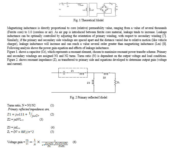
Figure 1. shows a theoretical model for a wireless power transfer circuit with a transmitting section and a receiver side. Below analysis will refer to transmitting section as primary coil or winding, and receiver section as secondary coil or winding. Leakage inductance (Lleak) is dependent on airgap between transmission and receiver windings while magnetizing inductance (Lm) is dependent on core material.


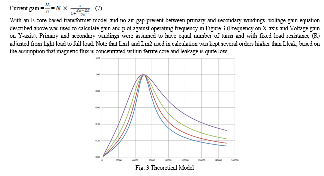
Linear region of the plot indicates stable operating frequency range and limiting operation within this region will ensure highest power transfer efficiency. For operating frequencies outside the linear region, a small perturbation in load will result in large output voltage swing and circuit could be unstable. Additional regulatory circuit will be necessary to ensure output voltage will not overshoot at light loads. Efficiency can be increased by choosing appropriate size of Cr, turns ratio and limiting operating frequency within the linear region of operation.
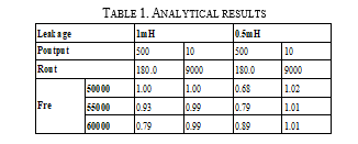
As explained previously, ferrite core without airgap provides a linear operating region and control scheme can be easily tuned to achieve maximum efficiency. This is primarily due to the low ratio between leakage inductance and magnetizing inductance. When air gap is introduced between primary and secondary windings or if the gap tends to vary both in magnitude and direction, leakage inductance tends to dominate and power topology becomes complex to deliver power transfer at maximum efficiency. Using the reluctance equation [4], we know that larger air gap length (lc) is directly proportional to the leakage inductance and an increase in air gap will reduce magnetic flux lines that would normally cross the secondary winding, thereby decreasing overall power transfer efficiency. For a given capacitance (Cr), turns ratio and fixed output power, rapidly changing Lleak will shift LC resonant circuit, and this will result in excessive primary current (for a given load). This is illustrated in Table 1, which shows Voltage gain analysis (equation 6) while leakage Lleak is changed from 0.5milliHenry (mH) to 1milliHenry (mH). Since the gain has changed significantly, output voltage tends to vary a lot. Hence an external regulator is needed to ensure output voltage is kept constant, both at no load and at full load conditions. This analysis was performed using excel calculation and results were plotted for load from 10watt (light load) to 500watt (full load).

With frequency of operation set between 50KHz to 60KHz, voltage gain will drastically shift from unity gain to a much lower value. For this analysis, we use equal magnetising inductance (Lm1 = Lm2) of 30.17mH with unity turns ration (N = 1), resonant capacitor of 0.01UF (Cr) and input voltage of 400Vdc.
Based on the analysis performed at various frequencies, light load tends to have higher gain and will drop as load is increased and operating frequency is shifted. This change gets exaggerated with different leakage inductances. If circuit operates close to resonant frequency, there is also a propensity for overvoltage and other stability issues at light load. This is partly due to unity gain and less immunity to circuit tolerances. To prevent overshoot, a pre-load resistor, with complex control loop may be needed. Such mitigations could help prevent the over voltage condition and provides additional safety measures, at the expense of increased cost, reduced efficiency and reliability. Alternatively, impedance matching transformer can help improve resonant waveform and achieve better output regulation. This approach will require additional a secondary side resonant tank designed with high quality factor and ensure near sinusoidal waveform [6]. This impedance matching technique will however result in a higher primary current, for a given output load condition. Since the component stress is directly proportional to the amount of circulating current, component losses will rise and will likely degrade overall power transfer efficiency. Therefore, overall analysis shows that a large leakage inductance resulting from a shifting air gap can complicate power system design and result in excessive product cost and reduce reliability.
IV. ACKNOWLEDGMENT
The author acknowledges that the research is conducted independently and there is no conflict of interest regarding the publication of this paper.
Conclusion
With complex geometrical surfaces like Electric vehicle charger, leakage inductance is going to be a dominating factor and such applications will suffer due to ever changing leakage inductance. Hence complex control mechanism is needed to address the need to regulate output voltage, reduce switching loss, and improve overall power transfer efficiency. In this paper, theoretical model for closely coupled magnetic surfaces was presented and was further analyzed to determine leakage inductance effect. Analysis was performance using theoretical equations and data presented as evidence. Voltage gain variation over a range of operating frequencies was also compared and it was found to result in a rapid shift the output voltage. This makes the implementation of Analog based control loop extremely difficult and using adequate safety mechanism could result in catastrophic conditions like overvoltage and circuit shutdown. This is evidence by 10% drop in voltage gain for 0.5mH variation in leakage inductance. This issue can be partly addressed by using Digital controllers, which present an ease of implementation. Closed loop control using digital means are best suited for applications with large inductance change. In some cases, impedance matching circuit may be necessary to ensure control loop stability. For future work, analysis presented in this paper will be extended to different cross-sectional surfaces and resulting leakage inductance will be analyzed for its impact on transfer efficiency.
References
[1] A. Zakarya, A. Yasir, and Y. Ahmad, \"Efficiency Examination of The Circular Coils with Two Types of Cross-Sections for WPT System,\" In Proceedings of the 1st International Multi-Disciplinary Conference Theme: Sustainable Development and Smart Planning, pp. 28-30 , 2020. [2] A. K. A. Kurs, R. Moffatt, J. D. Joannopoulos, P. Fisher, and M. Soljacic, “Wireless power transfer via strongly coupled magnetic resonances,” Science, vol. 317, no. 5834, pp. 83–86, 2007. [3] Siqi Li, Member, IEEE, and Chunting Chris Mi, Fellow, IEEE, Wireless Power Transfer for Electric Vehicle Applications, National Academy of Engineering, pp. 37-46, VOL. 3, NO. 1, 2015. [4] University of Colorado website [Online] Available: https://www.engr.colostate.edu/ECE562/98lectures/l25.pdf, pp-14. [5] Li. S and Mi, C .C. \"Wireless power transfer for electric vehicle applications,\" IEEE journal of emerging and selected topics in power electronics, no. 3(1), pp. 4-17, 2014. [6] University of Colorado website [Online] Available: https://scholar.colorado.edu/downloads/dr26xx59w, pp-32. [7] Laszlo Balogh, “A Practical Introduction to Digital Power Supply Control”, Texas Instruments, [Online] Available: https://www.ti.com/lit/ml/slup232/slup232.pdf. [8] Omar Abdelatty, Xiaoyu Wang, Amir Mortazawi, “Position-insensitive wireless power transfer based on nonlinear resonant circuits”, IEEE Transactions on Microwave Theory and Techniques, Volume 67, Issue 9, pp.3844-3855, March 2019. [9] Jingchen Wang 1 , Mark Paul Leach 1, Eng Gee Lim 1,*, Zhao Wang 1, Rui Pei 2, Zhenzhen Jiang 1 and Yi Huang, “Printed Split-Ring Loops with High Q-Factor for Wireless Power Transmission”, Electronics, 2021, MDPI, [Online] Available: https://www.mdpi.com/2079-9292/10/22/2884. [10] Ho, S.L.; Wang, J.; Fu, W.; Sun, M. A Comparative Study Between Novel Witricity and Traditional Inductive Magnetic Coupling in Wireless Charging. IEEE Trans. Magn. 2011, 47, 1522–1525. [11] Falavarjani, M.M.; Shahabadi, M.; Rashed-Mohassel, J. “Design and Implementation of Compact WPT link using Printed Spiral Resonators”. Electron. Lett. 2014, 50, 110–111. [12] Hany A . Atallah, “Compact 500 MHz Coupled Resonators Design Analyzed by J-Inverters for Wireless Power Transfer (WPT) Utilization, “, SVU-International Journal of Engineering Sciences and Applications, pp. 70-75, 2021. [13] R. Schlesinger and J. Biela, \"Leakage Inductance Modelling of Transformers: Accurate and Fast Models to Scale the Leakage Inductance Per Unit Length,\" 2020 22nd European Conference on Power Electronics and Applications (EPE\'20 ECCE Europe), Lyon, France, 2020, pp. 1-11. [14] Mogorovic, M.; Dujic, D. Medium frequency transformer leakage inductance modeling and experimental verification. In Proceedings of the Energy Conversion Congress and Exposition (ECCE), Cincinnati, OH, USA, 1–5 October2017.
Copyright
Copyright © 2023 Santosh Arcot. This is an open access article distributed under the Creative Commons Attribution License, which permits unrestricted use, distribution, and reproduction in any medium, provided the original work is properly cited.

Download Paper
Paper Id : IJRASET54635
Publish Date : 2023-07-06
ISSN : 2321-9653
Publisher Name : IJRASET
DOI Link : Click Here
 Submit Paper Online

