Ijraset Journal For Research in Applied Science and Engineering Technology
- Home / Ijraset
- On This Page
- Abstract
- Introduction
- Conclusion
- References
- Copyright
Integrated Fault Detection System for Underground Lines Using ESP32 and LORA Communication Using IOT
Authors: C. E. Mohan Kumar, Jaya Prasanth B R, Logesh Kumar S
DOI Link: https://doi.org/10.22214/ijraset.2024.60499
Certificate: View Certificate
Abstract
This paper introduces an advanced fault detection system tailored for underground line infrastructure, featuring the integration of ESP32 microcontroller technology and LORA communication protocols. The primary objective of this system is to enhance the reliability and efficiency of fault detection processes, crucial for maintaining the integrity of underground lines. At the core of this system lies the ESP32 microcontroller, serving as the central processing unit responsible for coordinating various functionalities. The detection mechanism incorporates six toggle switches strategically positioned along the underground lines, each assigned to monitor a specific location segment. In the event of a fault occurrence, the corresponding toggle switch is triggered, promptly initiating the fault detection process. Upon fault detection, the system seamlessly orchestrates the transmission of GPS location data to a LORA communication device. This data transmission mechanism ensures rapid dissemination of critical information regarding the fault\'s precise location. Additionally, an LED indicator is employed to provide immediate visual feedback, enabling quick identification of fault occurrences. Moreover, a LCD display unit offers real-time updates on the system\'s operational status, facilitating efficient monitoring and management. On the receiving end, the LORA communication device securely receives the transmitted data and forwards it to the cloud infrastructure using IOT technology. This cloud integration enables seamless data aggregation, storage, and analysis, empowering stakeholders with valuable insights into underground line health and performance.
Introduction
I. INTRODUTION
The scope of the project encompasses the design, development, integration, testing, deployment, and maintenance of an advanced fault detection system tailored for underground line infrastructure, with a focus on enhancing reliability and efficiency in fault detection processes.
- Safety (no end of life events or high energy open secondaries).
- High accuracy and linearity (no saturation effects). Digital secondary outputs.
- Flexible Form Factor (F3) current transducers (CT) (allowing mounting at ground or low potential
- (<10 kV) on any current carrying conductor without breaking the circuit).
- Isolation (sensors immune to nearby magnetic fields and currents).
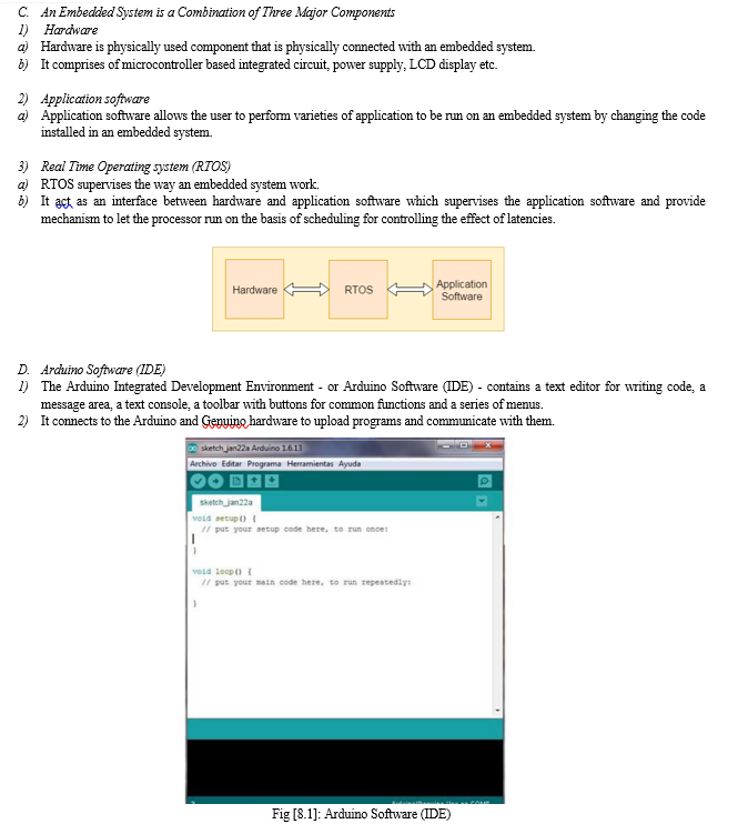
A. Experiment Set Up
- Embedded System Architecture
Designing of an embedded system
2. Basic Structure Of An Embedded System
Let's see the block diagram shows the basic structure of an embedded system.

- Sensor: Sensor used for sensing the change in environment condition and it generate the electric signal on the basis of change in environment condition. Therefore it is also called as transducers for providing electric input signal on the basis of change in environment condition.
- A-D Converter: An analog-to-digital converter is a device that converts analog electric input signal into its equivalent digital signal for further processing in an embedded system.
- Processor & ASICs: Processor used for processing the signal and data to execute desired set of instructions with high-speed of operation. Application specific integrated circuit (ASIC) is an integrated circuit designed to perform task specific operation inside an embedded system.
- D-A Converter: A digital-to-analog converter is a device that converts digital electric input signal into its equivalent analog signal for further processing in an embedded system.
- Actuators: Actuators is a comparator used for comparing the analog input signal level to desired output signal level for providing the error free output from the system.
B. Embedded System Implementation
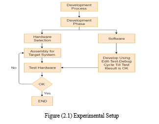
- Design Steps Required For The Development Of Embedded System
Designing steps required for embedded system are different from the design process of another electronic system.
Let's see a flow chart represent the design steps required in the development of an embedded system:
2. Embedded System Tools And Peripherals
a. Compiler
Compiler is used for converting the source code from a high-level programming language to a low-level programming language. It converts the code written in high level programming language into assembly or machine code. The main reason for conversion is to develop an executable program. Let's see the operations performed by compiler are:
- Code generation
- Code optimization
- Parsing
- Syntax direct translation
- Preprocessing
b. Cross-Compiler
If a program compiled is run on a computer having different operating system and hardware configuration than the computer system on which a compiler compiled the program, that compiler is known as cross-compiler.
c. Decompiler
A tool used for translating a program from a low-level language to high-level language is called a decompiler. It is used for conversion of assembly or machine code to high-level programming language.
d. Assembler
Assembler is embedded system tool used for translating a computer instruction written in assembly language into a pattern of bits which is used by the computer processor for performing its basic operations. Assembler creates an object code by translating assembly language instruction into set of mnemonics for representing each low-level machine operation.
3. Debugging Tools In An Embedded System
Debugging is a tool used for reducing the number of error or bugs inside a computer program or an assembled electronic hardware.
II. LITERATURE SURVEY
A fiber wrapped around the power conductor will have an induced Faraday effect creating false current signals. (In some cases, a ~10 km link can have a ~100 Arms pickup signal.) Also, as the power cable vibrates due to wind loading and ground motion, additional optical noise is present. This is due to the macro and micro bend loss in the cable. These unwanted signals interfere with the power line current measurement and are problematic and erratic over time. The objective of this study was to evaluate the water quality of the Cabra River through the use of aquatic macro invertebrates implementing the EPT and BMWP/Pan indexes. The diversity of orders and families of macro invertebrates was quantified, giving a total of 9460 individuals, distributed in 9 orders and 44 families. According to the BMWP/Pan, points P1 and P2 presented good quality waters from January to March, except for P2 which registered regular quality in February. P3 presented a transition from good quality waters to polluted waters from January to March. According to the EPT, points P1 and P2 presented waters of good quality from January to March. This paper presents a way for endeavoring cable voltage drop variation in the current. The transmitter unit with step up transformer has been used to locate the fault by a fault distance location by using an optimizing technique. The injecting a number of pulses in to the faulted cable in [11] proposed scheme aims to model and test the two popular cable Detecting an incipient fault in the underground cable is also a fault location methods i.e. Murray and Varley loop. In order to reduce the induced voltage of the metal sheath of the high-voltage cable, the metal sheath of the high-voltage cable is usually cross-connected in the transposition box of the cable cross-interconnection. In the process of reconnecting the cable line, the transposition is easy to be connected backwards, or even wrong. In addition, there will be many situations such as moisture, water intrusion, external force damage, resulting in cross-interconnection failures in the metal sheath of the high-voltage cable. Cross connect faults need to be dealt with in time. The paper analyzes the cross-connect faults of 110kV XLPE high-voltage cables, and uses PSCAD electromagnetic transient software to model and simulate. Simulation results summarize the characteristics of grounding current changes under different sheath faults. The results can provide a theoretical basis for the fault detection of the cable cross transposition system. We report a 3-D-stackable 1S1R passive cross-point resistive random access memory (RRAM). The sneak (leakage) current challenge in the cross-point RRAM integration has been overcome utilizing a field-assisted super linear threshold selector. The selector offers high selectivity of >107, sharp switching slope of 1011. Furthermore, we demonstrate 1S1R integration in which the selector sub threshold current is 102 memory ON/OFF ratio and >106 selectivity during cycling. Combined with self-current-controlled RRAM, the 1S1R enables high-density and high-performance memory applications.
III. METHODOLOGY
The outline of the IOT based Vehicle Carbon Monoxide Observing, Ready and Controlling Framework is displayed in Figure. Arduino Uno R3 is an open-source microcontroller which its board depends on ATmega328P. It has 14 computerized pins for information or result, which six of them can be utilized as PWM results, and six simple data sources. It very well may be fueled with a USB association or outer power supply 8 - 12 V. GSM SIM900A module (Small scale V3.8.2) is worked with double band GSM/GPRS. The sensor must run through high-heating and low-heating cycles to get proper measurements. The sensor requires a heater voltage that cycles between 5 V (high-heating) for 60 s and 1.4 V (low-heating) for 90 s. During the low-heating phase, CO is absorbed on the plate for measurement. During the high-heating phase, absorbed CO and other compounds evaporate and cleared from the sensor plate for the next measurement. The detection ranges from 10 to 1,000 PPM carbon monoxide. The output of the sensor is an analogue value, which needs to be converted to the level of carbon monoxide in PPM value. The higher the concentration of the carbon monoxide, the higher the voltage output.
The sensor is recommended to do calibration to adjust the sensitivities. A transfer is an electrically worked switch that works with a somewhat low voltage to turn on or switch off a high voltage circuit. It tends to be utilized to detach the connector at the vehicle start framework and mood killer the motor.
The transfer has Regularly Open (NO) contact, Ordinarily Shut (NC) contact furthermore, Normal (COM). COM is the middle terminal. For NO, the transfer will be in open contact state and no ongoing streams through when the transfer isn't set off. Then again, NC permits current stream when the transfer isn't set off. As the component of switching off the vehicle motor will require a wiring to the vehicle start framework, subsequently a Drove is used to address the vehicle in this undertaking and model improvement. Assuming the Drove is on, it shows that the vehicle motor is running. The Drove will be associated with the transfer and Arduino Uno.
The hand-off will go about as a change to switch off the Prompted demonstrate the motor is switched off. The vehicle or the Driven and transfer are known as the actuator of the framework. MIT Application Creator is an open-source web application that is used to make a completely practical Android application for cell phones or on the other hand tablets. It is straightforward and simple to utilize.
The application is written in Java and Kawa Plan. In this venture, the Android application is customized with the MIT Application Designer. Arduino IDE is an open-source programming to compose code and program the Arduino board. It can work on Windows, Linux, and Macintosh operating system X. The program is written in C or C++.The sketch can be transferred to the board by utilizing the USB B type link.
The cycle running in the Arduino board can be checked utilizing the chronic screen. Thing Speak is an open-source IOT application stage that permits ongoing sensor information assortment and stores the information in the cloud secretly or freely over the organization. Channel should be made to send and store information. It gives Programming interface keys for sending information to the channel and perusing the information from the channel [22]. In this venture, two Thing Speak channel, which is the Thing Speak Status Channel and Thing Speak Actuator Channel is made to store the information gather, which may not be timely or accurate enough to prevent significant crop damage. Existing pest management techniques may not.
IV. EXISTING SYSTEM
Technicians manually inspect underground lines, visually searching for signs of faults such as damaged cables, insulation issues, or loose connections. This approach is limited in terms of accuracy and efficiency. Inspecting a vast network of underground lines requires significant time and effort. Locating faults can be challenging, especially in large-scale distribution networks.
V. PROPOSED METHOD
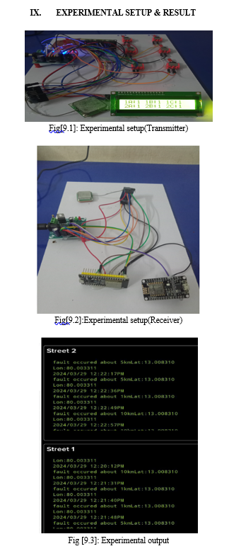
When a toggle switches is turned on, indicating a fault simulation the microcontroller records corresponding position on the grid. The system employs advanced algorithms to calculate the exact fault location based on the registered position and the known grid layout. The system is connected to an internet of things (IOT) platform through Wi-Fi or Ethernet.
Once a fault is detected and its location is determined the system updates the IOT platform with the fault information including the position on the grid. The system enables the precise detection and location of underground line faults. By monitoring the states of toggle switches and employing advanced algorithms, it can accurately pinpoint the exact location of a fault with in the simulated kilo meter distance.
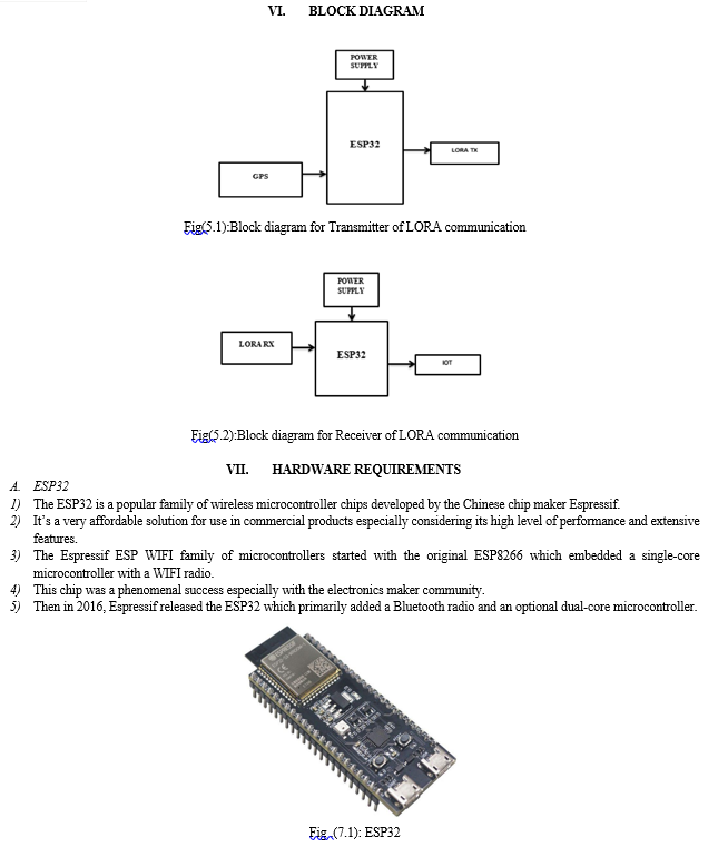
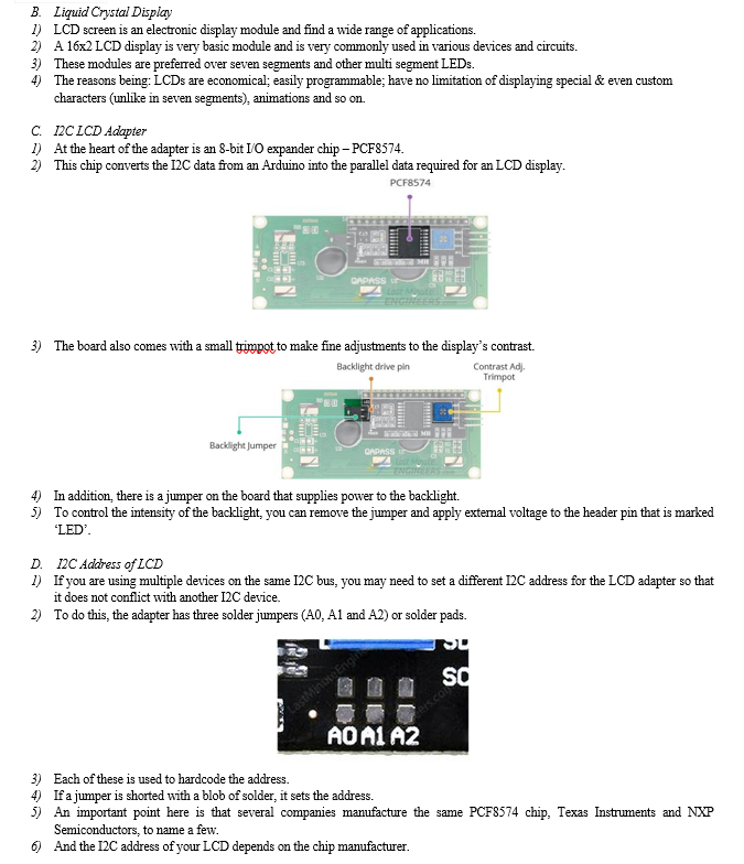
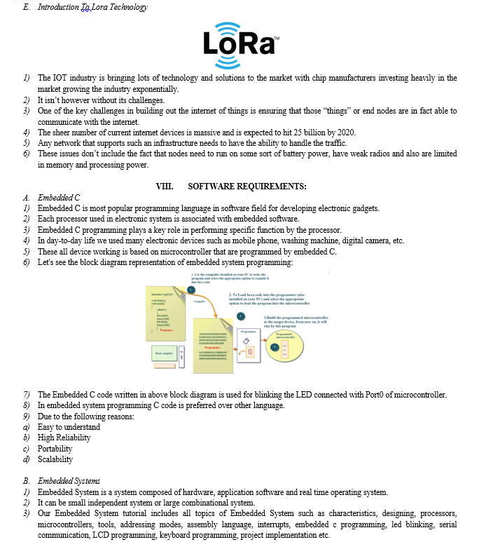
It offers a practical solution for underground lines fault detection without the need for expensive specialized equipment. The proposed fault detection system for underground line infrastructure integrates ESP32 microcontroller technology and LORA communication protocols.
It employs six toggle switches along the lines, each monitoring a specific segment. Upon fault detection, triggered switches initiate GPS data transmission via LORA. An LED indicator offers immediate feedback, while a LCD display provides real-time operational updates, enhancing system reliability.
At its core, the ESP32 microcontroller orchestrates fault detection processes, ensuring efficient coordination. When a fault occurs, the corresponding toggle switch triggers GPS data transmission via LORA, swiftly relaying precise location information. An LED indicator offers instant visual cues for fault identification, complemented by a LCD display providing real-time operational status updates.This system, integrating advanced microcontroller and communication technologies, aims to enhance the reliability and efficiency of underground line fault detection processes.
Conclusion
This article presents a novel PV array fault diagnosis scheme capable of distinguishing SC line fault from the MCPS effect. Unlike the traditional arts, the proposed scheme neither requires additional sensors and equipment nor disconnects the system for curve-scanning, which can bring additional cost or interruption. Instead, the proposed method diagnoses the faults based on the advanced concept of real-time identification during the regular MPPT process. The fault-detection algorithm can easily be incorporated into most of the currently installed PV array systems without hardware change. Besides, the judgments are based on system SLTC, which have been proven to be robust against complications and disturbances. The merits of the proposed scheme are verified by simulations and experiments.
References
[1] U. Khalil et al., “Comparative analysis of photovoltaic faults and performance evaluation of its detection techniques,” IEEE Access, vol. 8, pp. 26676–26700, 2020. [2] M. K. Alam, F. Khan, J. Johnson, and J. Flicker, “A comprehensive review of catastrophic faults in PV arrays: Types, detection, and mitigation techniques,” IEEE J. Photovolt., vol. 5, no. 3, pp. 982–997, May 2015. [3] M. Köntges et al., Review of Failures of Photovoltaic Modules. Paris, France:International Energy Agency, 2014. [4] A. F. Murtaza, M. Bilal, R. Ahmad, and H. A. Sher, “A circuit analysisbased fault finding algorithm for photovoltaic array under L-L/L-G faults,” IEEE J. Emerg. Sel. Topics Power Electron., vol. 8, no. 3, pp. 3067– 3076, Sep. 2020. [5] R. Hariharan, M. Chakkarapani, G. Saravana Ilango, and C. Nagamani, “A method to detect photovoltaic array faults and partial shading in PV systems,” IEEE J. Photovolt., vol. 6, no. 5, pp. 1278–1285, Sep. 2016. [6] S. Roy, M. K. Alam, F. Khan, J. Johnson, and J. Flicker, “An irradiance independent, robust ground-fault detection scheme for PV arrays based on spread spectrum time-domain reflectometry (SSTDR),” IEEE Trans. Power Electron., vol. 33, no. 8, pp. 7046–7057, Aug. 2018. [7] U. Khalil et al., “Comparative analysis of photovoltaic faults and performance evaluation of its detection techniques,” IEEE Access, vol. 8, pp. 26676–26700, 2020. [8] M. K. Alam, F. Khan, J. Johnson, and J. Flicker, “A comprehensive review of catastrophic faults in PV arrays: Types, detection, and mitigation techniques,” IEEE J. Photovolt., vol. 5, no. 3, pp. 982–997, May 2015. [9] M. Köntges et al., Review of Failures of Photovoltaic Modules. Paris, France: International Energy Agency, 2014. [10] A. F. Murtaza, M. Bilal, R. Ahmad, and H. A. Sher, “A circuit analysisbased fault finding algorithm for photovoltaic array under L-L/L-G faults,” IEEE J. Emerg. Sel. Topics Power Electron., vol. 8, no. 3, pp. 3067– 3076, Sep. 2020. [11] R. Hariharan, M. Chakkarapani, G. Saravana Ilango, and C. Nagamani, “A method to detect photovoltaic array faults and partial shading in PV systems,” IEEE J. Photovolt., vol. 6, no. 5, pp. 1278–1285, Sep. 2016. [12] S. Roy, M. K. Alam, F. Khan, J. Johnson, and J. Flicker, “An irradiance independent, robust ground-fault detection scheme for PV arrays based on spread spectrum time-domain reflectometry (SSTDR),” IEEE Trans. Power Electron., vol. 33, no. 8, pp. 7046–7057, Aug. 2018. [13] U. Khalil et al., “Comparative analysis of photovoltaic faults and performance evaluation of its detection techniques,” IEEE Access, vol. 8, pp. 26676–26700, 2020. [14] M. K. Alam, F. Khan, J. Johnson, and J. Flicker, “A comprehensive review of catastrophic faults in PV arrays: Types, detection, and mitigation techniques,” IEEE J. Photovolt., vol. 5, no. 3, pp. 982–997, May 2015. [15] M. Köntges et al., Review of Failures of Photovoltaic Modules. Paris, France:International Energy Agency, 2014. [16] A. F. Murtaza, M. Bilal, R. Ahmad, and H. A. Sher, “A circuit analysisbased fault finding algorithm for photovoltaic array under L-L/L-G faults,” IEEE J. Emerg. Sel. Topics Power Electron., vol. 8, no. 3, pp. 3067– 3076, Sep. 2020. [17] R. Hariharan, M. Chakkarapani, G. Saravana Ilango, and C. Nagamani, “A method to detect photovoltaic array faults and partial shading in PV systems,” IEEE J. Photovolt., vol. 6, no. 5, pp. 1278–1285, Sep. 2016. [18] S. Roy, M. K. Alam, F. Khan, J. Johnson, and J. Flicker, “An irradiance independent, robust ground-fault detection scheme for PV arrays based on spread spectrum time-domain reflectometry (SSTDR),” IEEE Trans. Power Electron., vol. 33, no. 8, pp. 7046–7057, Aug. 2018. [19] M. K. Alam, F. Khan,J.Johnson, and J. Flicker, “PV ground-fault detection using spread spectrum time domain reflectometry (SSTDR),” in Proc. IEEE Energy Convers. Congr. Expo., 2013, pp. 1015–102. [20] T. Pei, L. Li, J. Zhang, and X. Hao, “Module block fault locating strategy for large-scale photovoltaic arrays,” Energy Convers. Manag., vol. 214, 2020, Art. no. 112898. [21] Y. Hu et al., “Online two-section PV array fault diagnosis with optimized voltage sensor locations,” IEEE Trans. Ind. Electron., vol. 62, no. 11, pp. 7237–7246, Nov. 2015. [22] P. Jain et al., “A digital twin approach for fault diagnosis in distributed photovoltaic systems,” IEEE Trans. Power Electron., vol. 35, no. 1, pp. 940– 956, Jan. 2020.
Copyright
Copyright © 2024 C. E. Mohan Kumar, Jaya Prasanth B R, Logesh Kumar S. This is an open access article distributed under the Creative Commons Attribution License, which permits unrestricted use, distribution, and reproduction in any medium, provided the original work is properly cited.

Download Paper
Paper Id : IJRASET60499
Publish Date : 2024-04-17
ISSN : 2321-9653
Publisher Name : IJRASET
DOI Link : Click Here
 Submit Paper Online

