Ijraset Journal For Research in Applied Science and Engineering Technology
- Home / Ijraset
- On This Page
- Abstract
- Introduction
- Conclusion
- References
- Copyright
Laminar Flow Heat Transfer Studies in a Twisted Square Duct for Constant Wall Temperature
Authors: Rambir Bhadouriya
DOI Link: https://doi.org/10.22214/ijraset.2024.58090
Certificate: View Certificate
Abstract
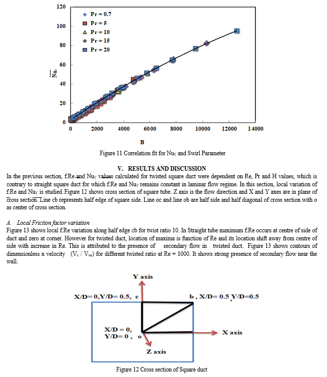
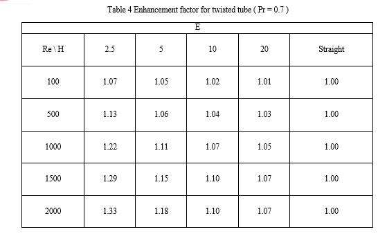
Three dimensional analysis of steady fully developed laminar flow inside twisted duct of square cross section flow area is studied for Reynolds number range of 100 – 2000 using a commercially available software. Twist ratio used are 2.5, 5, 10 and 20. Heat transfer results are generated for a uniform wall temperature case for Prandtl number range of 0.7 to 20. Maximum values for the product of friction factor and Reynolds number is observed for a twist ratio of 2.5 and Reynold number of 2000. Maximum Nusselt number is observed for the same values along with Prandtl number of 20. Correlations for friction factor and Nusselt number are developed involving swirl parameter. Local distribution of friction factor ratio and Nusselt number across a cross-section is presented. Heat transfer enhancement for Reynold number of 2000 and Prandtl number of 0.7 for twist ratio of 2.5, 5, 10, and 20 are 33 %, 18 %, 10 % and 7 % respectively. The results are significant because it will contribute to development of compact heat exchanger.
Introduction
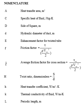
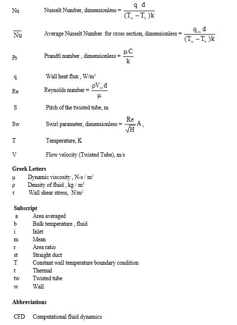
I. INTRODUCTION
Heat transfer enhancement techniques can be classified either as passive, which require no direct application of external power, or as active, which require external power. The effectiveness of both types of techniques is strongly dependent on the mode of heat transfer. This may range from single-phase free convection to dispersed-flow film boiling. Twisted duct works on the principle of passive enhancement technique. One of the ways of heat transfer enhancement is to create swirl in the flow.
In ducts, heat transfer augmentation by means of secondary flow is obtained either by means of an insert (e.g. twisted tape) in straight duct or by using a twisted duct. Twisted duct used in heat exchanger not only enhances heat transfer inside the ducts but also outside in duct to duct space. Thus, the mixing of the fluid is significantly improved. Swirl induced flow inside the duct is expected to enhance the heat transfer coefficient by an amount similar to that of twisted tape or turbulator inserts. Todd (1977) investigated a general problem of twisted tube.
He simplified the Navier-Stokes equations under large twist ratio assumption in the rotating coordinates which were solved by a regular perturbation method. Author defined the large twist ratio as ratio when change in twist angle (θ) of cross section of duct with respect to direction of flow (z) is very small (dθ/dz <<1). He derived a fourth order partial differential equation for the stream function and showed that it is identical to the equation for the small transverse displacement of a clamped elastic plate under a constant loading. Although, this analysis is applicable for a pipe of any cross section with proper boundary conditions, its validity is limited only to a large twist ratio elliptic pipe.
Masliyah and Nandakumar (1981a and 1981b) numerically studied the fully developed steady laminar flow through twisted square ducts with rotation coordinates system. Axial conduction in fluids was neglected to preserve the two dimensional nature of the problem. The temperature along the periphery is assumed to be constant for each wall. However, this constant temperature might be different for each of the four walls.
The swirling motion enhanced the heat transfer for a twist ratio of 2.5 and Reynolds number range of 1-1000. Similar expected enhancement was not observed for other twist ratios. Later Xu and Fan (1986) pointed out discrepancy in the viscous dissipation term adopted by Masilyah and Nandakumar (1981a and 1981b).
Chang et al. (1988) studied laminar flow in a twisted elliptic tube for large twist ratios (H = 21, 53, 106) using finite difference method. The effect of twist ratio and aspect ratio of ellipse is investigated with respect to their role in determining the axial and circumferential velocities and streamline patterns. Bishara (2010) numerically studied laminar, periodically fully developed single phase flow of a Newtonian fluid in helically twisted tube with constant wall temperature boundary condition for Re range of 10-1000 and Pr of 3.
Elliptical tubes with aspect ratio 0.3, 0.5 and 0.7 and twist ratio of 6, 9 and 12 were considered. Twisted elliptical tube showed considerable heat transfer enhancement compared to straight tube. Yang et al. (2011) experimentally evaluated performance of five twisted elliptical tubes. Aspect ratio (major diameter / minor diameter) of elliptical tubes used was in the range 1.49 to 2.15 and twist ratio range covered was 17.4 – 32.8. Water was used as the working fluid for Re range of 600 – 55000 covering laminar, transition and turbulent regime. They concluded that for twisted duct flow remains laminar for Re ≤ 2300. In twisted tube heat transfer enhancement is higher for laminar regime compared to transition and turbulent flow regime.
Literature review suggests that heat transfer and flow resistance charactertics of fluid flow inside twisted duct was studied. Numerical studies done on twisted elliptical tube are for Re range of 10 – 1000 and Pr range of 3 – 5. Twist ratios employed are in range of 6 – 106.
There is not much literature available on twisted square duct. Numerical solutions for entire laminar flow regime are not available. Prandtl number range covered is narrow.
Twist ratio used are high which will not contribute much to heat transfer enhancement studies. Literature does not address mechanism of heat transfer enhancement. Studies are discrete and there is a need for an equation to predict friction factor and heat transfer solution for a wide range of Reynold number and Prandtl number.
In the present study, an effort is made to study the pressure drop and heat transfer in a twisted square duct for a Reynolds number ranging from 100-2000 and Prandtl number ranging from 0.7 - 20. FLUENT is used as the CFD tool to generate the fluid flow and heat transfer distribution in a square twisted duct for a range of twist ratios (2.5 – 20). Heat transfer enhancement mechanism is explained by providing local distribution of friction factor and Nusselt number in duct cross section. Objective is to generate correlation to predict friction factor and Nusselt number for entire range of parameters studied.
II. COMMON TERMINOLOGY OF TWISTED SQUARE DUCT
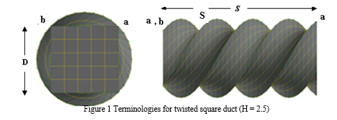
Common terminologies associated with twisted duct have been highlighted in Fig. 1 are as follows
- Pitch (S): The distance between two consecutive points along the length of tube where the orientation of tube cross section exactly coincides to each other. Cross section rotates by 360° along one pitch distance.
- Twist Ratio (H): It is the geometrical parameter used to describe flow through twisted ducts. It is defined as the ratio of the pitch (S) to hydraulic diameter (d) of the duct.
III. NUMERICAL METHODOLOGY
FLUENT software has the ability to provide solution of fluid flow and heat transfer by using periodic flow concept. Periodic flow conditions exist when the flow pattern repeats over some length L, with a constant pressure drop across each repeating module along the flow direction. In the case of twisted duct, as the geometry of duct repeats, a suitable modelling length (S/4) of twisted duct was considered and periodic flow concept was utilized to obtain the solution. As for periodic flows, such problems can be analysed by restricting the numerical model to a single module of periodic length. This permits the use of a scaled model and reduces the computational time. Based on the experimental investigation of Yang et al. (2011) flow is considered to be laminar for studied Re range of 100 – 2000. Prandtl numbers considered are 0.7, 5, 10, 15 and 20. Twist ratio considered are 2.5, 5, 10 and 20. Three dimensional models are used in the analysis with hexahedron mesh elements. Peripherally and axially uniform wall conditions boundary conditions are used. Body forces due to gravity are neglected. Solutions are obtained for steady state, incompressible, hydrodynamically and thermally developed flow using FLUENT (version 6.2.16).
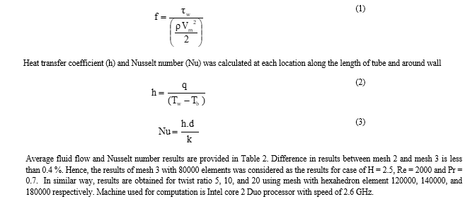
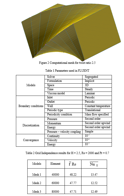
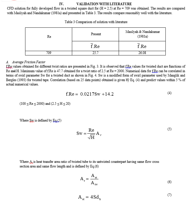
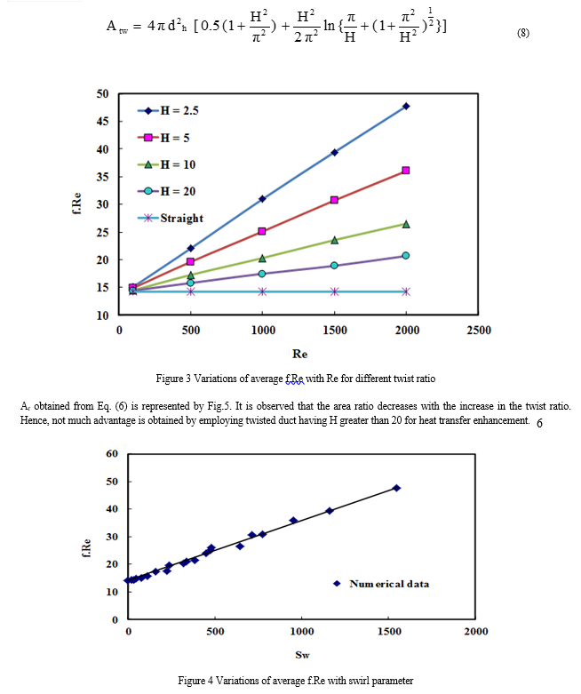
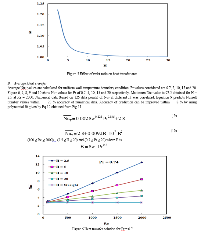
Common calculation methodology adopted in the present study is one case (H = 2.5, Re = 2000 and Pr = 0.7) of solution is presented. Twisted square duct (H = 2.5) of periodic Length (S/4) is meshed with hexahedron elements. Three meshes with elements 40000, 60000 and 80000 are generated. Figure 2 shows meshed model for twist ratio 2.5 with 80000 elements. Fluid flow and heat transfer solution is obtained in FLUENT as per the parameter listed in Table 1. Wall temperature (Tw), bulk temperature (Tb), heat flux (qw) and shear stress (τw) data is obtained from FLUENT at different location along the length of the duct. Friction factor can be obtained from wall shear stress as


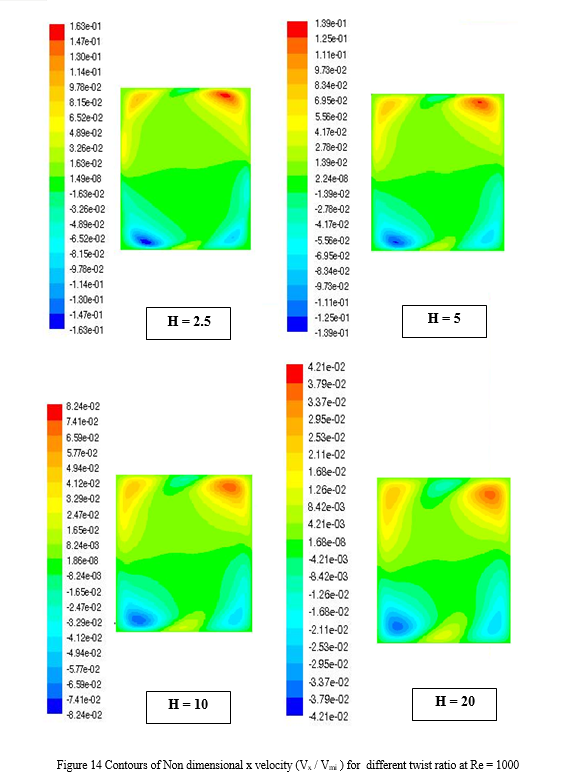
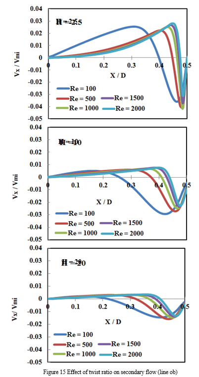
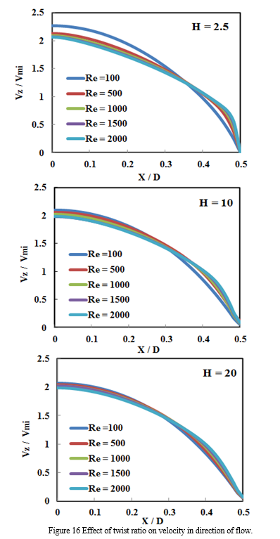
Region. Also it is seen that magnitude of secondary flow is higher for small twist ratio. To analyse it further Vx and Vz component of velocities are plotted for different twist ratios. Figures 15 and 16 shows Vx and Vz component of velocities respectively along line ob. Velocities are non-dimensionalized with respect to mean inlet velocity (Vmi). It is seen from Fig. 15 that secondary flow reduces with increase in twist ratio. From Fig.16 it is observed that maximum Vz occurs at center of duct and it is 2.1 times that mean inlet velocity or mean velocity at given cross section for H= 2.5 & Re = 2000. It can be concluded that Vx (same as Vy) component of velocity is mainly responsible for creating swirl in flow and it is more effective at smaller twist ratios. Contrary to straight square duct where Vx and Vy component of velocities are nearly zero compared to Vz component, twisted duct shows comparable values of this components. Vx and Vy components of velocities observed are maximum for H = 2.5 and is about 2.56 % of inlet mean velocity. It is also seen that location of maximum value of Vx and Vy velocity component is in region of X/D = 0.3-0.5, which is near wall region. For a given twist ratio, as Re is increased, location of maximum value of x and y component shifts towards wall. For a given Reynolds number as twist ratio is decreased location of maximum of x and y component shifts towards wall. X and y components of velocity generated (also referred as secondary flow) are result of swirling motion occurring inside the twisted tube. As magnitude and location of secondary flow are function of Re and twist ratio, Shear stress at wall and hence f.Re values will also be function of the same. Observation leads to conclusion that swirling motion (secondary flow) is responsible for higher f.Re values and it distribution at given cross section in case of twisted duct.
B. Local heat Transfer Variation
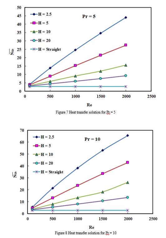
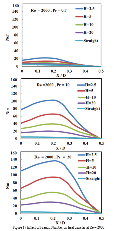
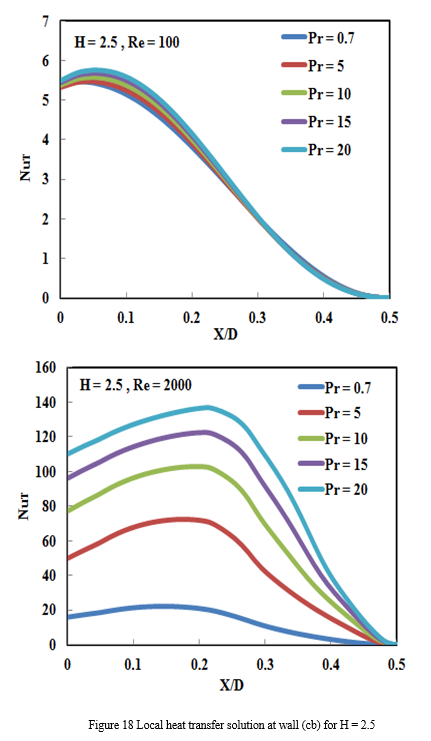
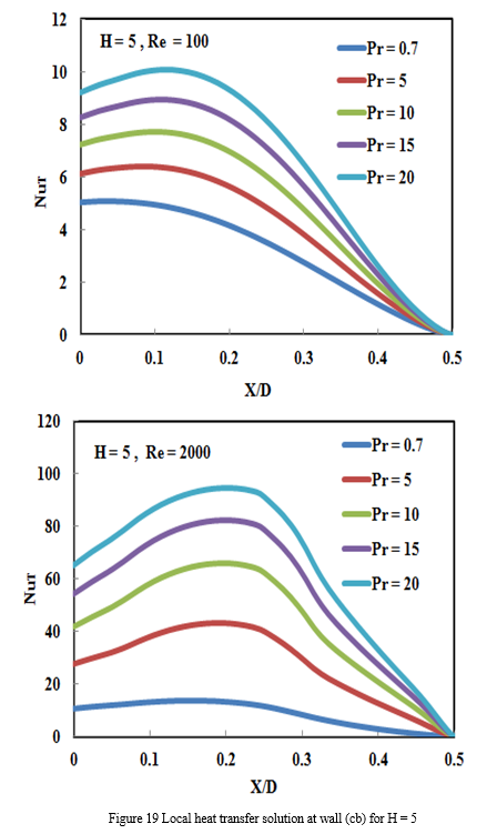
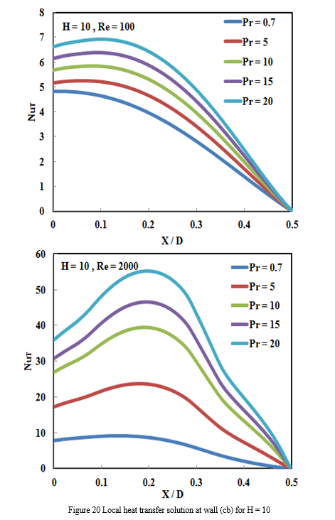
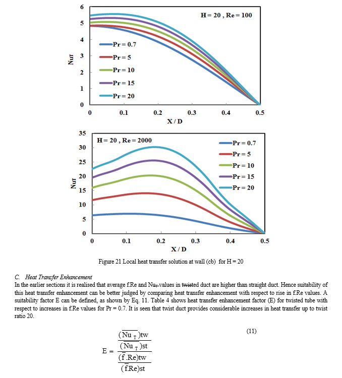
In the earlier section, it was found that NuT values for twisted square ducts were dependent on Re and Pr values. In this section local Nusselt number variation along the wall has been analysed. Figure 17 shows local NuT variation along cb at Re = 2000. It is seen that for same twist ratio as Nu increases with Pr. It is observed that at given Re and Pr as twist ratio decrease NuT increases. Also at given Re and H as Pr increase NuT values increases. Figure 18, 19, 20 and 21 shows NuT solutions for twist ratio 5, 10, 15 and 20 respectively. It is seen that location of maximum NuT is not at center of edge (point c) as expected for straight duct .Location of maximum NuT point depend on H and Re. Location of maximum NuT point shifts away from point c with increase in the magnitude of secondary flow. This is important observation as it will determine location of maximum heat flux point on duct wall.
Conclusion
In the present work, fluid flow and heat transfer solution had been obtained for fully developed laminar flow with uniform peripheral wall temperature boundary condition. Reynolds number range considered was 100 – 2000 and Prandtl number was 0.7 – 20. Twist ratio used was 2.5, 5, 10 and 20. Average friction factor and Nusselt number correlation are generated in terms of swirl parameter. Maximum average Nusselt number was reported was for H = 2.5 at Re = 2000. Nusselt number was found to be direct function of Re and Pr and inverse function of H. Local distribution of friction factor and Nusselt number are provided and it is found that location of maxima changes with Reynolds number, Prandtl number and twist ratio. Comparison of heat transfer enhancement with respect to friction factor had been provided in terms of enhancement factor. Maximum value of enhancement factor for Pr = 0.7 is 1.33 and it is for H = 2.5 at Re = 2000. It is found that twisted tube enhancement heat transfer in the studied range of parameters hence it is good substitute for straight tube in heat exchange equipment’s operating under similar parameters. These will contribute in one way for development of compact heat exchanger.
References
[1] Bishara F., 2010. Numerical simulation of fully developed Laminar flow and Heat transfer in Isothermal Helically Twisted tubes with Elliptical cross-section, M.S. Thesis, University of Cincinnati, Cleveland state, USA. [2] Chang K.S., Choi J.S. and Kim J.S., 1988. Laminar fluid flow in a Twisted Elliptic tube, KSME Journal, Vol.2, No.1, pp. 44-51. [3] Manglik R.M. and Bergles A.E., 1993. Heat transfer and Pressure drop Correlations for Twisted –Tape inserts in isothermal flows, Journal of Heat transfer, Vol.115, pp. 881-889. [4] Masliyah J.H. and Nandakumar K., 1981a. Steady Laminar flow through Twisted pipes - Fluid flow in Square tubes, ASME journal of Heat Transfer, Vol. 103, n4, pp.785-790. [5] Masliyah J.H., and Nandakumar K., 1981b. Steady Laminar flow through Twisted pipes - Heat transfer in Square tubes, ASME journal of Heat Transfer, Vol. 103, n4, pp. 791-795. [6] Todd L., 1977. Some comments on steady Laminar flow through Twisted pipes, Journal of Engineering Mathematics, Vol.11, pp. 29-48. [7] Xu C.G. and Fan D.N., 1986. Some Remarks on the Helical Cartesian coordinates system and its application, ASME J. Heat transfer, 108, pp. 483-486. [8] Yang S., Zhang L. and Xu H., 2011. Experimental study on Convective heat transfer and flow resistance characteristics of water flow in Twisted Elliptical tubes, Applied Thermal Engineering, 2011, Article in press, pp. 1-11.
Copyright
Copyright © 2024 Rambir Bhadouriya. This is an open access article distributed under the Creative Commons Attribution License, which permits unrestricted use, distribution, and reproduction in any medium, provided the original work is properly cited.

Download Paper
Paper Id : IJRASET58090
Publish Date : 2024-01-18
ISSN : 2321-9653
Publisher Name : IJRASET
DOI Link : Click Here
 Submit Paper Online

