Ijraset Journal For Research in Applied Science and Engineering Technology
- Home / Ijraset
- On This Page
- Abstract
- Introduction
- Conclusion
- References
- Copyright
Designing of Light Weight Hall Thrusters with Key Discharge Parameters
Authors: Kaveesh Kanagaraj, Maharajan N V, Riya Dewangan, Swarina Arthur James
DOI Link: https://doi.org/10.22214/ijraset.2024.60696
Certificate: View Certificate
Abstract
A study was conducted to design and fabricate a light-weight Hall thruster with all key discharge parameters. Hall thrusters are firmly used as the primary electric propulsion in the current field of space propulsion. The concepts of electric and magnetic fields are studied to improve the thrust and specific impulse of the light-weight Hall thruster. This model is intended to work within a range for certain near-Earth missions. The Hall thruster is designed in CAD software with all the required parts, dimensions and the materials that had to be used for its light weight consideration. The compact Hall thruster’s key discharge parameters are discussed and designed accordingly in order to produce a higher thrust-to-power ratio.
Introduction
I. INTRODUCTION
Hall effect Thrusters are rapidly emerging as a technology to become the most common form of electric propulsion in space. Electric propulsion thrusters are an attractive option for wide range of missions in space. It could be used for various purposes such as orbital maneuvering, spacecraft attitude and orbit control. Electric propulsion uses safe inert gases such as Krypton or Xenon to produce thrust in a quasi-plasma state, unlike chemical rockets. Although, chemical rockets are known for its higher thrust, electric propulsion have ability to produce higher specific impulse (Isp), change in velocity achieved by kilogram of propellant. The working of Hall effect Thrusters is simple. A plasma is formed withing an annular channel where an axial electric field is formed to accelerate and eject plasma ions to generate thrust. The plasma is usually formed by bombarding a gaseous propellant with high energy electron trapped by a radial magnetic field. The HET gets its name from the azimuthal drift-enabled Hall current that results from trapped electrons at any point within the annular channel being able to "drift" in a direction perpendicular to both fields due to the radial magnetic and axial electric fields. The electric and magnetic field are deeply looked into as its going to reflect with the overall performance and efficiency of this electrostatic thruster. Aiming to provide higher thrust as light weight the electric field and magnetic field are designed accordingly. The aim of this paper is to design light weight hall thrusters with key discharge parameters. The context of research comes with a CAD model of Hall thruster which is a single anode-layer. The importance of light weight hall thrusters is well known for missions in LEO (lower earth orbital) and MEO (medium earth orbital) with CubeSat and autonomous geo-spatial positioning satellites, requires lower weight to maintain the velocity radially with respect with the earth’s centre of mass. Also, light weight Hall thrusters can reduce large economic costs for its orbital positioning in space. This paper also deals primarily with the key discharge parameters required for the thruster to maintain precise control over the ionization distribution. Taken into considerations of the discharge parameters such as discharge voltage, magnetic field strength and propellant mass flow rate which plays a crucial role in determining how efficiently propellant is ionized and distributed with in the thruster channel. These parameters are very important in designing and developing hall thrusters.
II. HALL EFFECT THRUSTER DESIGN CONSIDERATIONS
High specific Impulse of hall effect thrusters could be understood from the rocket equation below

Where V is the necessary change in spacecraft velocity for the mission, g is the gravitational acceleration (at the Earth's surface), and Isp is the specific impulse. The initial and final spacecraft masses are Mi and Mf, respectively. Equation 1 demonstrates that we should maximize the specific impulse in order to maximize the useful payload. Systems that rely on chemical propellants have a limited specific impulse of 200–400 seconds. However, specific impulses in the range of several hundred to several thousand seconds are produced by electric propulsion systems. Any thruster system's objective is to accelerate ions, which are particles with a finite mass as opposed to electrons' insignificant mass. It is helpful to take into account the ions' total kinetic and electric potential energy at a very high level.
The design of our light weight hall thruster employs two coils concentric to the discharge channel. High coil currents greater than 5 A are necessary for the inner coil to achieve magnetic shielding of the channel walls. Due to their small heat conduction paths and high currents, the electromagnet’s temperatures are likely higher than the maximum operating temperature of conventional enamelled copper cables. The electromagnets use a nickel wire with glass fiber insulation that can tolerate constant temperatures of up to 450°C in order to prevent damage. Due to the thick insulation layer, the wire diameter is significantly larger than that of an enamelled copper wire with the same conductor cross-section area. To obtain adequate coil windings, the thruster needed to be extended in the axial direction. [1]
III. CONCEPT OF ELECTRIC AND MAGNETIC FIELD
Electrons confined in the main channel bombard the propellant, causing it to become ionized. A magnetic field that is radial traps electrons. After that, an axial electric field is supplied to cause electrons to drift in the direction of , producing an azimuthal velocity (a drift-enabled Hall current). The electric field produced by the device is used to accelerate ionized propellant away from the thruster and to move electrons from the cathode into the channel. Because the cathode has a lower voltage than the anode, electrons generated by it are pulled into the channel. Electrons need to travel at a specific speed in order to remain trapped in the channel since the magnetic field is what holds them there. [3]
The electric field of the device is used to accelerate ionized propellant away from the thruster and to transfer electrons from the cathode into the channel. Electrons generated by the cathode are attracted into the channel because of the cathode's negative potential in relation to the anode. [3]
Electrons need to travel at a specific speed in order to remain trapped in the channel since the magnetic field is what holds them there. They stay in the channel's plasma for a while, but ultimately, they run out of energy due to collisions with the wall or other particles (such neutrals). An electron returns to the circuit and is transferred back to the cathode when it reaches the anode at the bottom of the channel.[3][2]
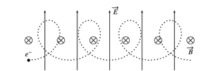
FIG.1 An electron in a homogenous electric and magnetic field experiencing E B drift follows a cycloidal trajectory. In the magnetic field, the electron has a tendency to circle anticlockwise; however, the electric field imposes an extra constant acceleration, which makes the electron move more quickly near the bottom of the circle. A constant rightward drift velocity is the end result.[4]
IV. HOW LIGHT WEIGHT HALL THRUSTERS INCREASE THE EFFICIENCY IN TERMS OF ELECTRIC AND MAGNETIC FIELD
A. Electric Field
- Thrust-to-Weight Ratio: In applications like satellites or deep space missions where reducing spacecraft mass is crucial, lightweight Hall thrusters are frequently utilized. These thrusters can produce more thrust in relation to their own weight at increasing electric field intensities, which raises the thrust-to-weight ratio.
- Performance: Increased thrust output and specific impulse are two benefits of the greater electric field intensities. This makes it possible for lightweight Hall thrusters to effectively generate the thrust needed for a variety of mission scenarios.
B. Magnetic Field
- Ion Control: Precise control of the paths of ions inside the thruster requires precisely calibrated magnetic field settings. Lightweight Hall thrusters may maximize the acceleration and direction of ions, leading to more effective thrust generation, by precisely sculpting the magnetic field.
- Plume Expansion: Exhaust plume expansion can be managed with the use of intricate magnetic field designs. Thruster designers may control the density and shape of the plume by varying the magnetic field, which minimizes interactions with spacecraft components and lowers the possibility of damage or interference. [4]
V. DESIGNING OF THE MAGNETIC FIELD FOR LIGHT WEIGHT THRUSTERS
Permanent magnets and electromagnets are two simple ways to create the required magnetic field. Permanent magnets have the advantages of dependability, not requiring a power source, and not producing excess heat during operation; however, they are constrained by Curie temperature and field strength and are not changeable. The only limits on the magnetic field produced by electromagnets are the heat rating of the current-carrying wire and the power supply that is available. In either scenario, directing the field into the required shape requires the use of a magnetic shunt which works on the principle of ferromagnetism. [1]
Even if there is a significantly excessive positive electric potential gradient, the electrons cannot approach the anode due to the sufficiently strong magnetic field. However, because of their comparatively greater mass in relation to the mass of the electrons, ions are unaffected by the magnetic field. The migration of these electrons is known as the Hall Effect. The azimuthal direction is shown by the Fleming left hand rule, the cross arrangement of the electric and magnetic fields causes electrons to form the Hall Current. [3]
VI. MAGNETIC LENS FOR LIGHT WEIGHT THRUSTERS
The longevity and performance of HETs are directly impacted by the magnetic lens design. The magnetic field is highest close to the exit plane and rapidly decreases to zero right before the anode surface in an ideal magnetic lens. In order to prolong thruster life and lessen ion bombardment of the channel walls, the magnetic field lines curvature may also be engineered [1]. The thruster will fail when the channel walls are eroded because the plasma will be in close contact with the electromagnetic coils. A magnetically shielded thruster is one that is made with a magnetic lens that almost completely blocks out this bombardment; these thrusters need intricate designs that are outside the purview of this study. A magnetic circuit made up of one centre coil and several outer coils is used to form the magnetic lens.
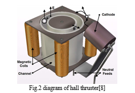
Magnetic Field Strength: Lightweight and heavy-weight Hall thrusters may have different magnetic field strengths inside their lenses. Higher magnetic field strengths can be used in lightweight thrusters to ensure effective ion acceleration and control, while heavier thrusters may require lower magnetic field strengths because of their bigger size and distinct operating requirements.
Ion Control: To enable effective thrust generation and plasma confinement, the magnetic lens in lightweight Hall thrusters is optimized to offer precise control over ion trajectories. The magnetic lens of heavy-weight rockets might be less concerned with precise ion control and more with overall plasma stability and performance.[5]
VII. KEY DISCHARGE PARAMETERS
A. Discharge Voltage
A discharge voltage is the amount of battery voltage available for the mission at any given point while the battery is discharging. The discharge voltage directly affects the electric field strength within the discharge channel. Higher discharge voltage creates stronger electric field, which can accelerate electrons to higher energies, which might produce higher thrust. As, the discharge voltage directly affects the distribution of electric field, the moment of ions and electrons, their density during the discharge process affect the performance of the thruster. These electrons with the energy collide with the propellant atoms, leading to increased ionization rates. By creating a particular channel structure that reduces the interaction between the particles and the channel walls, one can change the discharge channel structure. This increases the ionization rate, which in turn increases the thrust. However, excessively higher discharge voltages can also lead to:
- Electron-wall interactions: High-energy electron could bombard the thruster wall which could lead to erosion and reduced life span.
- Secondary electron emission: The collision between high-energy electrons and thruster walls can liberate secondary electrons contributing to discharge wall erosion.
Therefore, one important area of research to focus on is how discharge voltage affects the Hall propulsion system's performance.[6]
B. Magnetic Field Strength:
Hall thrusters create magnetic field through electromagnetic coils. AS, the magnetic field strength influences the trajectory of electrons within the thruster discharge channel. Stronger the electric field the electrons are confined tightly with higher ionization efficiency and also preventing them from reaching the thruster walls. However, an excessively strong magnetic field can also:
- Reduce electron mobility: Electrons become trapped within the magnetic field lines, hindering their ability to collide with propellant atoms and reducing ionisation efficiency.
- Limit ion acceleration: A strong magnetic field can impede the acceleration of ionised propellant species, negatively impacting thrust generation
Between the anode at the base of an annular channel and the hollow-cathode plasma generated outside the thruster channel, an axial electric field is created. It is not possible for electrons from this cathode plasma to stream straight to the anode due to a transverse (radial) magnetic field. Rather, the electrons spiral around the channel in the E B azimuthal direction (into the page) and along the magnetic field lines (as shown), diffusing to the anode and channel walls through collisional processes and electrostatic fluctuations. The propellant that is injected into the channel from the anode area is effectively ionized by the plasma discharge produced by the electrons in the crossed electric and magnetic fields. This plasma's ions bombard and sputter degrade the dielectric walls near the channel outlet, hence determining the thruster's lifespan. This plasma also bombards the dielectric wall with electrons, which deposits a large quantity of power in this area.
An axial electric field in the channel accelerates the ions to generate the thrust beam because the transverse magnetic field's lower axial electron mobility allows the applied discharge voltage to be spread along the channel axis in the quasi-neutral plasma. Consequently, even though a magnetic field is essential to the operation, Hall thrusters are referred to be electrostatic devices since the provided electric field accelerates the ions. [7]
C. Propellant mass flow rate:
The propellant mass flow rate is a crucial factor that determines the number of propellant atoms present within the thruster channel for ionization. A higher mass flow rate increases the density of neutral propellant, which can have several implications:
- Enhanced Collisions: With a higher mass flow rate, there are more propellant atoms present in the thruster channel. This increases the likelihood of collisions between electrons and propellant atoms, promoting higher ionization rates. The increased density of neutral propellant due to the higher mass flow rate facilitates more frequent interactions with electrons, resulting in enhanced ionization.
- Reduced Ionization Efficiency: However, at very high mass flow rates, there is a possibility that the available electrons might not be sufficient to ionize all the propellant atoms present. As a result, this can lead to a decrease in the overall ionization efficiency. This phenomenon occurs when the mass flow rate is so high that the available electrons cannot keep up with ionizing all the propellant atoms, leading to a reduction in efficiency.
- It's important to note that as the mass flow rate increases, larger quantities of propellant are utilized within the mission. Therefore, understanding and optimizing the propellant mass flow rate is essential for achieving efficient and effective thruster performance.[7]
- Summarizing Ionization Distribution: The spatial distribution of ionisation within a Hall thruster plays a critical role in thruster performance and operation. The ionization process in hall thrusters involves the ionization of propellant atoms in the discharge channel which are accelerated to produce thrust. The distribution of ionization is influenced by several factors such as discharge voltage, mass flow rate, magnetic field strength, and structure of the discharge channel. Here's how discharge parameters influence this distribution:
- Discharge Voltage: A higher discharge voltage can lead to a more uniform ionisation distribution across the multiple stages of the thruster. However, excessively high voltages can result in increased ionisation near the thruster entrance, leading to inefficiencies.
- Magnetic Field Strength: A gradually decreasing magnetic field profile across the stages can optimise ionisation distribution. A stronger magnetic field in the initial stages promotes efficient ionisation, while a weaker field in the later stages allows for improved ion acceleration.
- Propellant Mass Flow Rate: A moderate mass flow rate is crucial for achieving a balanced ionisation distribution. Too low of a flow rate can lead to underutilised ionisation potential, while too high a flow rate can create regions of under-ionisation within the thruster.
VIII. THRUSTER AND CATHODE DESIGN
A tiny, permanent-magnet HET that was created by the former Olin College team showed an unstable pulsed free using argon propellant. Four recommendations for significant design changes were made in correspondence with the previous team: utilize electromagnets to allow for real-time magnetic field variation; use krypton, a propellant that is more easily ionizable; and refrain from using a hollow cathode, which is prohibitively expensive to purchase and difficult to build. The thruster for this study was designed with fresh learning conducted as part of the independent study in mind, as well as design considerations.
The "tyranny of the rocket equation" is essentially a propellant weight concern: when more propellant is added to a spacecraft, the system mass increases and longer thruster burns are required to accelerate the increased system mass. This establishes a feasible cap on the volume of fuel transported, such as at a specific point, adding more propellant will only result in slight changes in velocity (v). Maximizing the propellant's exit velocity, or vex, will increase a thruster's momentum transfer efficiency while lowering the amount of propellant required to reach the target velocity. Through the use of electromagnetic fields, electric propulsion engines can accelerate propellant to much higher speeds than chemical rockets, acting as a class of thrusters which generate lower thrust than chemical rockets but with higher propellant exit velocities, much higher specific impulse could be obtained.[3]
The three parameters that define a thruster's initial design are thrust, specific impulse, and power. The unit of trust, T, stands for the force that the apparatus can produce. The specific impulse, or Isp, is the ratio of thrust to weight following propellant and stands for a rocket's ability to generate a net change in velocity effectively. Power in this context refers to the anode-to-cathode circuit's power, which is the ability of electrons to flow through the thruster channel's plasma from the cathode to the anode. Two of these numbers have to be selected when designing a thruster based on the requirements and constraints of the mission or spacecraft design.[3]
IX. SYSTEM INTEGRATION AND VACCUM CONSIDERATION
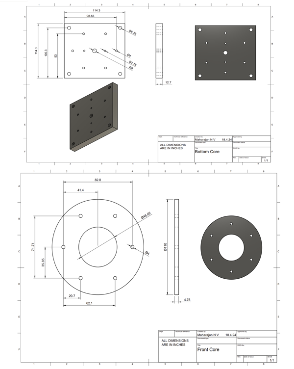
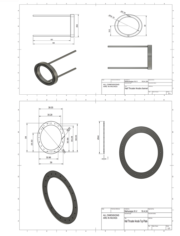
Keeping in track of our low weight design consideration, the interior parts of the hall thrusters are designed accordingly. The complexity of the system integration heavily depends upon the chamber, sensing suite and associated components.
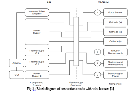
From Fig:1 we could observe the following wire connection with respect to the gas flow and off-gassing. As we know the gas discharges from the anode into the channel whereas the flow rate of the gas is controlled with omega FMA6502ST displayless gas controllers. As there is light magnetic shielding in the discharge channel due to sputtering, Gas lines leaks are checked even though we use an inert gas, we should minimize the usage of the fuel by considering the power and magnetic coupling. Wiring harness is a complicated task to bind the satellite in two regimes, that is between the air and vacuum side. A feed connector as in fig 1, connects both the air and vacuum region, thus wiring harness is very important for interior thermal property of the thruster to work stable in vacuum condition. Considering about outgassing, significant problem for chambers that have small at higher vacuum levels they are less capable to perform significant. Minimizing the use of volatile organic compounds or other gases keeps the discharge chamber clean. For instance, Kapton could be used for its electrical insulation and thermal conduction.[3][2]
X. AMOUNT OF PLASMA DENSITY IN A LIGHT WEIGHT HALL THRUSTER (1.5 TO 3 KW)
It is noteworthy that a Hall thruster plasma retains quasi neutrality; in the event that the plasma's total charge is biased in one direction, the plasma will either repel charges of the same sign as the bias or draw back charges of the opposite sign. The cathode and thruster anode are connected by a power supply. In order to neutralize the plume, this supply transfers electrons that were caught on the thruster anode and moved to the cathode, where they were released into the thruster's ion beam. The spacecraft would accumulate a net negative charge if this weren't the case since ions are ions that were released and ejected would be drawn back towards the thruster, reversing any momentum that was first obtained from firing them.[3]


XII. MATERIAL SELECTION ANALYSIS
A. Wall Material
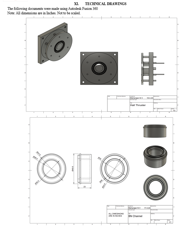
The wall material is usually made from mixture of Boron Nitride Ceramics as they possess a High thermal conductive nature, High thermal shock resistance as satellites are exposed to varying temperature fluctuations, low density and high dielectric strength. A comparative study has been done on analysis of performance of various other materials for wall material and the result came out to be a significant factor for material selection. The thrust performance of hall thruster and plasma characteristics are significantly affected by the nature of material used for the wall because of its dielectric or thermal properties.
B. Front and Back Plates
The front and back plates are commonly made from either stainless steel or thick iron bars as it ensures the longevity and promising thermal behaviour of the hall thruster under fluctuating temperature exposure.
C. Magnetic Coil
Aluminium is preferred over other magnetism exhibiting metals due to various reasons. For example, Copper is one of the good magnetisms exhibiting metal found commonly like Aluminium. But Aluminium has ~60% conductivity of copper while being around 30% of its weight. Therefore, usage of Aluminium is crucial due to its excellence in magnetism while being light weight.
D. Miscellaneous
Other parts such as the anode components are usually machined from materials like 316 Stainless Steel, Iron. Usage of Graphite is preferred for Anode component. For the insulation parts, ceramics of Alumina or Macor (Machinable Glass Ceramics) are used due to their non conductive less weight properties.
XIII. ALTERNATIVE MATERIAL SELECTION
Due to the emerging technology in Additive manufacturing methods, few components of the hall thruster have been made from 3D printing method and was analysed for its performance. A study has been conducted for the same using ULTEM material which is a family of Polyimide thermal resins known for its high thermos-resistance behaviour, High dielectric strength, stiffness and ease of machinability. It is one of the best-in-class thermoresistant polyimide resin that we can find. However, the study resulted in the failure of usage of ULTEM for not more than 30 seconds of operation as there was a formation of hotspot/failure mode on the wall of ULTEM discharge channel. This study helped in proving that thermos-resins are not suitable for any usable components in a hall thruster due to the extreme temperature fluctuation in outer space.
Also, there were other challenges that additive manufacturing possesses such as post-shrinkage cooldown effect, part accuracy of the printer used to print, surface finishing etc.
XIV. PROPELLANT SELECTION
Xenon is the majorly used propellant for hall thrusters due to its Lowest first ionisation potential, inert behaviour, comparatively higher mass. However, since it is used for almost every type of electric propulsion methods, its abundancy and availability in nature is reducing considerably. Therefore, the search for an alternative is on rise. Krypton is the widely used alternative for hall thruster due to its highly similar xenon like properties while having less mass. Moreover, Krypton produces 25% more specific impulse than xenon at higher discharge powers. Other options of propellants are also being studied such as condensable propellants, usage of Iodine but usage of any propellant comes with its own disadvantage. Since the aim of this study is to develop a less weight hall thruster, usage of krypton is preferred without sacrificing any performance of thrust and specific impulse.

Conclusion
From the design and overall parameters taken to design the Hall thrusters are governed accordingly, construction of light weight Hall thrusters are made possible from the following process and material selection. The CAD model demonstrates the design of the light weight Hall thruster with all discharge parameters taken into consideration. Electric and magnetic field should be focused primarily for producing higher thrust and specific impulse in a Hall thruster. Even though the Hall thrusters are light, they could produce higher thrust to power ratio. System integration and vacuum consideration are outlined to design the Hall thruster’s discharge channel accordingly. Light weight propulsion is very important for Low earth and medium earth orbital missions. Production of thrust for missions such as debris removal, radio-signal processing, CubeSat integrated thrusters could be easily accessible using this technology.
References
[1] Bozkurt, E., & ALEMDARO?LU, H. (2021). DESIGNING AND TESTING OF A 1.5 kW HALL EFFECT THRUSTER. [2] Jorns, B., Marks, T. A., & Dale, E. T. (2020). A Predictive Hall Thruster Model Enabled by Data-Driven Closure. In AIAA Propulsion and Energy 2020 Forum. American Institute of Aeronautics and Astronautics. https://doi.org/doi:10.2514/6.2020-3622 [3] Baird, Matthew, \"Designing an Accessible Hall Effect Thruster\" (2016). Honors Theses. 2697. https://scholarworks.wmich.edu/honors_theses/2697 [4] Oh, B., Countryman, A., Regassa, M., Clowes, A., Miner, G., Kemp, S., McAneney, S. C. “Mack,” Klein, M., & Lee, C. (2023). Design, fabrication, and testing of an undergraduate hall effect thruster. Journal of Electric Propulsion, 2(1), 6. https://doi.org/10.1007/s44205-023-00040-3 [5] Baird, Matthew, \"Designing an Accessible Hall Effect Thruster\" (2016). Honors Theses. 2697. https://scholarworks.wmich.edu/honors_theses/2697 [6] Petronio, F. (2023). Plasma instabilities in Hall Thrusters: a theoretical and numerical study. [7] Simmonds, J., Raitses, Y., & Smolyakov, A. (2023). A theoretical thrust density limit for Hall thrusters. Journal of Electric Propulsion, 2(1), 12. https://doi.org/10.1007/s44205-023-00048-9 [8] Stark, W., Gondol, N., & Tajmar, M. (2022). Concept and design of a hall-effect thruster with integrated thrust vector control. Journal of Electric Propulsion, 1(1), 21. https://doi.org/10.1007/s44205-022-00023-w [9] Thomas, C., Sommier, E., Gascon, N., & Cappelli, M. (2006). The Magnetic Interference Hall Accelerator. In Collection of Technical Papers - AIAA/ASME/SAE/ASEE 42nd Joint Propulsion Conference (Vol. 8). https://doi.org/10.2514/6.2006-4993 [10] Brown, N.P.; Walker, M.L.R. Review of Plasma-Induced Hall Thruster Erosion. Appl. Sci. 2020, 10, 3775. https://doi.org/10.3390/app10113775
Copyright
Copyright © 2024 Kaveesh Kanagaraj, Maharajan N V, Riya Dewangan, Swarina Arthur James. This is an open access article distributed under the Creative Commons Attribution License, which permits unrestricted use, distribution, and reproduction in any medium, provided the original work is properly cited.

Download Paper
Paper Id : IJRASET60696
Publish Date : 2024-04-21
ISSN : 2321-9653
Publisher Name : IJRASET
DOI Link : Click Here
 Submit Paper Online

