Ijraset Journal For Research in Applied Science and Engineering Technology
- Home / Ijraset
- On This Page
- Abstract
- Introduction
- Conclusion
- References
- Copyright
Design and Manufacturing of Compound Die
Authors: Prof. Jaware A. R., Shrikant Gite, Mahadev Jagtap, Aniket Godase, Sachin Jadhav
DOI Link: https://doi.org/10.22214/ijraset.2024.62047
Certificate: View Certificate
Abstract
The work deals with the development of a combined tool for improvement of a process to be done in piaggio product manufacturing plant. Research work deals with combining two press operations done separately. This operation is done for piaggio battery support bracket, cradle assembly, Bumper cargo. In the first pressing blanking process is done. And in the second operation a hole is pierced in the same product. The objective of research is to develop a tool and process for using a single press for performing dual operation. This is also to reduce downtime, reduce operator fatigue and thereby increase production. Elimination of one operation, one operator and reduction in processing time is also to be achieved.
Introduction
I. INTRODUCTION
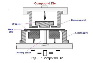
A die is a specialized tool used in manufacturing industries to cut or shape material using a press. Like moulds, dies are generally customized to the item they are used to create. Products made with dies range from simple paper clips to complex pieces used in advanced technology. Piercing dies are typically made by tool and die makers and put into production after mounting into a press. The die is a metal block that is used for forming materials like sheet metal and plastic. For the vacuum forming of plastic sheet only a single form is used, typically to form transparent plastic containers (called blister packs) for merchandise. For the forming of sheet metal, such as automobile body parts, two parts may be used, one, called the punch, performs the piercing, stretching, bending and blanking operation, while another part, called the die block, securely clamps the w/p and provides operation.

Design of sheet metal die is a large division of tool engineering, it has a rather complex and a fascinating subject which has its own importance and pertains to the added value of the particular industry. It is by far the most exacting of all areas of the general field of tool designing. The die designer originates the design of die employed, stamped and formed part from sheet metal, assemble the parts together and perform a variety of operations.
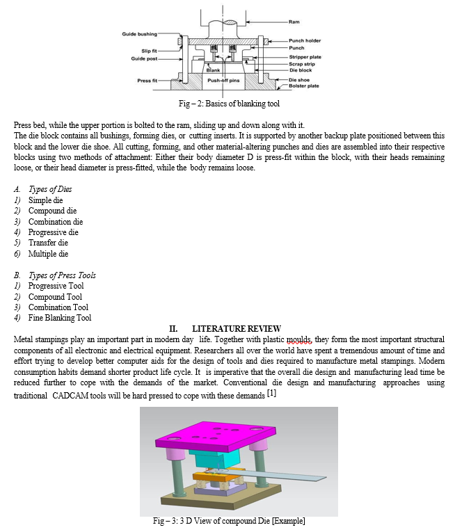
Basics of blanking and piercing tool - A blanking die produces a flat piece of material by cutting the desired shape in one operation. The finished part is referred to as a blank. Generally a blanking die may only cut the outside contour of a part, often used for parts with no internal features. Piercing is a shearing process where a punch and die are used to create a hole in sheet metal or a plate. The process and machinery are usually the same as that used in blanking, except that the piece being punched out is scrap in the piercing process. A die, as mounted in the press, is a complex action mechanism, producing parts in predetermined sequence. The lower half of the die, mounted, on the lower die shoe, is firmly attached to the

The fine blanking technology of cam were analysed, its blank layout was designed, the fine blanking source was calculated and stamping equipment selected. The fine blanking die clearance and rounded edge were determined. The fine blanking compound die structure was designed. The materials and heat treatment specifications of fine blanking mould work parts were selected and the gear plate structure designed. Practice shows that the process program used was reasonable [2] Due to the current trend towards lightweight design and multi-material design, the focus more than ever is on mechanical joining technologies, as thermic joining methods reach their limits with regard to joining of dissimilar materials. At the present time, the main mechanical joining technique for the realisation of innovative material mix in automotive construction is semi-tubular self-piercing riveting. [3]
The influence of the blank holder die gap size on the MDD process was investigated via experiments and FEM simulation. MDD is a typical type of micro forming technology that fabricates micro cup and box like products. The in process spring back occurs when the blank escapes from the blank holder, which is beneficial for reducing the drawing force. A small gap is preferred for reducing the non uniform distribution of the wall thickness on the drawn cup while not increasing the risk of fracture. [4]
Etsuro Katsuta and Hiroshi Morita concludes that in the dry piercing process steel sheets under nearly zero clearance is developed with use of the plasma nitride punch and die core system, High pressuring plays a key to reduce the occurrence of ductile fracture during the piercing process. The stress concentration at the punch edge corner and the core edge plays a role to make reliable micro piercing process. [5]
Based on the study of the piercing process of sheet assisted by magnetic medium, the paper puts forward that the factors such as loading speed, punch diameter, current intensity and sheet thickness are taken as the important process conditions. The traditional forming technology is difficult to meet actual needs of modern production.
III. OBJECTIVES
Aim of the project is to increase productivity, to reduce human effort, to reduce cycle time, to reduce labour cost, to design blanking and piercing die, to develop blanking and piercing die. Better product manufacturing capability in masses.
IV. METHODOLOGY
Steps involved in the entire process
- Press selection
- Die design
a. Design checked and approved
b. Final approval from department
3. Die manufacturing
a. Procurement of material
b. Machining of raw material type
c. Milling
d. Grinding
e.Turning
f. Material handed over to the fitting section
4. Fitting Section
a. Fitting of the top plate
b. Holder fitted on top plate and drilled, reamed and dowelled
c. Holder pocket CNC machined
d. Inserts drilling and counter boring for aligning screws
e. Holder is drilled and tap for inserts
f. Insert fitting on holders and drill reaming and dowelling
g Top plate ready for CNC
h. Top pad manufacturing dummy plate and ready for CNC
i. Fitting of the bottom plate
j. Bearing block for guide pillar drill cutter
k. Riser block drill cutter
l. Drill tap of bottom plate for bearing block and riser block
m. Fitment of the bearing block and riser block and drill reaming and dowelling
n. Insert drill cutter
o. Riser drill taps for inserts
p. Insert fitting and drill reaming and dowelling
q. Bottom ready for CNC
r. Bottom pad ready for CNC
5. After CNC
a. Top
- Inserts relieving machining
- Forming punch cylinder grind and fitment
b. Bottom
- Insert relief drill for pierce hole and other relieve machining
- Heat treatment of inserts
- Guide pillar and bush centre grinding + die set making
- Bottom insert fit after heat treatment
- Shearing of top insert [check clearance between punch and die and pierce punch alignment]
- Do spotting or shearing and grinding if any
- Top inserts heat treatment
V. MATERIAL SELECTION
Material selection ensures the integrity at design. IN the selection process, materials will be accessed for tensile strength and modulus, flexural strength and modulus, Impact strength, compressive strength, fatigue strength, creep, and stress relaxation properties depending on the application.


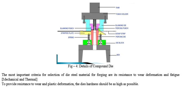
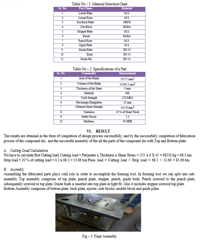
Back plate and side blocks screwed to bottom plate. Ejectors and middle block is screwed to back plate, while guide pillar inserted into bottom plate in tight fit.
VII. FUTURE SCOPE
Earlier, the process of die design was considered an art rather than the science. Traditionally, checking the manufacturability of sheet metal parts and process of die design require experienced die designers, involve numerous calculations, and hence time-consuming tasks. But with the advancement in the field of AI around 1980s, these are being carried out using various AI techniques. But most of the systems developed using AI techniques are having limitation in extraction and representation of part feature data in more interactive format for displaying output.
Further, most of the systems are developed for single- operation stamping dies using production rule-based Very few systems are developed for design of multi-operations dies and even these are not capable to fully automate the die design process. Therefore, there is need to develop an intelligent system by combining some suitable AI technique and CAD system for manufacturability assessments/reasoning, concurrent planning and quick design of multi-operation dies.
The system must have rich knowledge base comprising knowledge of experienced die designers and process planners, must be interactive and user friendly and have low cost of implementation. The system finally must give its output in form of drawings of strip-layout, die components and die assembly. The authors are applying their research efforts in this direction to assist process planners and die designers of small and medium scale sheet metal industries.
Further, we can reduce the number of component of the die by using the material selection method as we can eliminate the pad and use the support plate as both support and pad. We can also reduce the shut height which can optimize the production time as the ram required to travel less distance.
VIII. ACKNOWLEDGEMENT
Every orientation work has imprint of many people and this work is no different. This work gives me an opportunity to express deep gratitude for the same. While preparing project we received endless help from number of people. This project would be incomplete if we don’t convey our sincere thanks to all those who were involved in this. First and foremost, we would like to express us deep sense of gratitude and indebtedness to our Guide Prof. Supriya S. Gadhe Department of Mechanical Engineering, for their invaluable encouragement, suggestions and support from an early stage of this project stage 1 and providing us an extraordinary experiences throughout the work. Above all, her priceless and meticulous supervision at each and every phase of work inspired us in innumerable ways. We specially acknowledge her for her advice, supervision, and the vital contribution as and when required during this project. Her involvement with originality has triggered nourished our intellectual maturity that will help us for a long time to come. We are proud to record that we had the opportunity to work with an exceptionally experienced professor like her. We are highly grateful to the Principal Dr. U. P. Naik and Head of The Department A.R.JAWARE, Adsul Technical Campus, Chas, Ahmednagar for their kind support and permission to use the facilities available in the Institute.
Finally, we wish to thank my friends and my family for being supportive, without whom this project would not have seen the light of the day. Every work is an outcome of full proof planning, continuous hard work and organized effort. This work is a combination of all the three put together sincerely.
Conclusion
1) Successfully designed a blanking and piercing die operations. 2) The tool could be utilized in mass production to produce identical parts with good geometrical tolerances. 3) By choosing appropriate tool steels for die, punch and other parts, the tool life could increase for maximum range. 4) Time Saving, less movement of the part which reduces fatigue to operator. 5) Less cost of manpower and production. 6) One time investment in the requisite equipment would ensure a long term supply of superior quality products, generating huge profits for the manufacturers.
References
[1] J.A.W.Hijink, T.H.Elndhoven , A.C.H. Van Der WolF “On the design of die-set ” annals of the CIRP,vol 24, (1975) . [2] S. Badrinarayanan “Perform and die design problems in metal Forming” Cornell University (1997). [3] Nicholas zabaras And akkaram Srikanth “An object-oriented programming approach to the lagrangian fem analysis of large inelastic deformations and metal forming processes international journal for numerical methods in engineering”. 45,399– 445, (1999). [4] P.C.Sharma,“Production engineering”S.chand publication ,1st edition (1982) [5] Vamshikrishna reddy chada , “Computer aided design of sheet metal die assembly utilispro / engineer and mechanica” B.tech. Jawaharlal nehru Technological University, India, (2007). [6] Wilson Burton, Jon Carlson, Brad Cobb, Amber Monceaux ,Tyler Ray ,Ron York“Manually operated punch press Design report draft 3”(2008). [7] Mohammad Haider, K. K. Pathak, Geeta Agnihotri “Perform design for near net shape close die gear forging using simulation technique”, Archives of Applied Research, 2 (6):317-324, (2010 ). [8] Iulian stanasel, florin blaga and ioan radu “Research on parametric design of die punch”. Academic journal of manufacturing engineering, vol. 10, issue 1, (2012). [9] Milash Kumar Lahadotiya, Abhay Dinkar Kakirde and Asutosh Kumar Pandey “Mini Review on Designing of Press Tools for Sheet Metal Parts” JECET Vol.2.No.3, 650-660, (2013) [10] Mr. Amit D. Madake, Dr. Vinayak R. Naik, Mr. Swapnil S. Kulkarni “Development of a Sheet-Metal Component with a Forming Die Using CAE Software Tools (Hyper form) Vifor Design Validation and Improvement” International Journal of Modern Engineering Research, Vol. 3, Issue. 3, Pp-1787- 1791, (2013).
Copyright
Copyright © 2024 Prof. Jaware A. R., Shrikant Gite, Mahadev Jagtap, Aniket Godase, Sachin Jadhav. This is an open access article distributed under the Creative Commons Attribution License, which permits unrestricted use, distribution, and reproduction in any medium, provided the original work is properly cited.

Download Paper
Paper Id : IJRASET62047
Publish Date : 2024-05-13
ISSN : 2321-9653
Publisher Name : IJRASET
DOI Link : Click Here
 Submit Paper Online

