Ijraset Journal For Research in Applied Science and Engineering Technology
- Home / Ijraset
- On This Page
- Abstract
- Introduction
- Conclusion
- References
- Copyright
Mechanical Characterization of Pultruded GFRP Round Tube under Axial Loading
Authors: L. T. Mane, A. M. Tone, Prof. M. D. Jagtap
DOI Link: https://doi.org/10.22214/ijraset.2024.60748
Certificate: View Certificate
Abstract
Pultruded Fibre?Reinforced Polymer profiles are widely used as structural elements in many civil infrastructure applications. However, the anisotropic elasticity and the application?driven slenderness make these profiles prone to local buckling failure, well below their ultimate load capacity. In this paper, an experimental study was undertaken to characterise the tensile and compressive failure of GFRP round tube under axial loading. Based on the research focus of GFRP structures, this work will present a comprehensive study of the mechanical properties of GFRP tubes in terms of both tensile and compressive loads and investigate the mechanical parameters. This paper presents an investigation on the mechanical properties of pultruded Glass fiber reinforced polymer (GFRP) round tubes for structures subjected to tensile and compressive axial loading. The tensile and compressive strength of GFRP round tubes were first tested. For the stability under compression, the slenderness ratio 6 is adopted. The results show that the tensile strength of GFRP tube could reach 580 MPa, while the compressive strength has been around 72% of tensile strength. Also Experimental results showed that specimens exhibited linearly elastic up to failure. Compared with the single tensile failure mode of GFRP tubes, two types of compressive failure modes, including micro-buckling and local buckling were observed. Moreover, a finite element (FE) analysis was carried to simulate the tensile and compressive behaviours of round tube specimen. The comparison between the tensile and compressive peak load values obtained experiment and FE methods revealed that their difference is less than 5%. These indicated that FE analysis predicted reasonably the actual tensile and compressive behaviours of the pultruded GFRP round tube.
Introduction
I. INTRODUCTION
Applications of Glass Fiber Reinforced Polymers (GFRP) elements have grown steadily during the last years, as they became extremely popular in different areas of the aerospace, automotive, marine, O&G (oil and gas) and civil construction industries, namely (fiberglass structures): ladders, platforms, handrail systems tank, pipe and pump supports [1]. The development of GFRP for commercial use occurred in the 1940s, particularly due to interest to the naval industry [2]. Afterward, the global production speedily increased, reaching the current development in the late 1960s [2], when the combination of low material and production costs and advances fabrication of members, finally make polymer production economical and diffused to other fields. Moreover, GFRP presents very flexible design solutions, due to its extraordinary fabrication adaptability, high durability and structural efficiency (strength-to-weight ratio) and its usage also benefits from increasingly low production and erection costs.
GFRP is a category of plastic composite that specifically uses glass fiber materials to mechanically improve the strength and stiffness of plastics [4] – the resin provides additional protection to the fiber due to the bounding between materials [4]. Among the different methods of forming GFRP members, the pultrusion, which emerged in the USA in the 1950s [1, 2], was used to produce the GFRP profile. Fibre-reinforced polymer (FRP) composites are meeting an increasing demand as construction material due to their excellent properties including light weight, high specific strength, corrosion resistance, and low maintenance cost. These characteristics made them a suitable alternative in replacing traditional materials such as concrete, steel, and timber in various applications in construction industry. GFRP composites can be made by pultrusion, a mechanised process for producing continuous sections. The process consists of pulling impregnated filaments together with a mat or fabric through a heated die [1]. This method provided an advantage in terms of product consistency and economy in manufacturing closed-section profiles including GFRP composite tubes [2]. These tubes have been also used as a structural decking component in bridges [5].
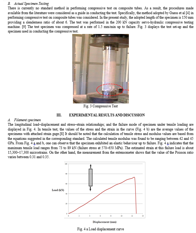
This paper presents the characterisation of the mechanical properties of a 50 mm round pultruded tube used as GFRP handrail in Refinery. The main objective of this work is to investigate the behaviour of the tube under tensile and compressive loadings. Tests on specimens were undertaken to determine the mechanical properties of the tube. The tensile test was conducted following the standards defined in ASTM D638, and compressive test was conducted following the standards defined in ASTM D695.
Aside from these tests, a finite element analysis (FEA) was carried to simulate the tensile and compressive behaviours of tube specimen. The results obtained from the experiment were compared with those of FEA.
II. EXPERIMENTAL METHODOLOGY
A. Material
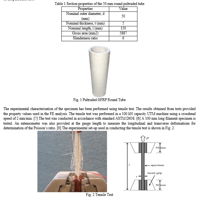
The round composite tube (Fig. 1) investigated is made from vinyl ester resin with E-glass fibre reinforcement and manufactured using the process of pultrusion. [7] The mass density of the pultruded tube is 1970 kg/mm3. Table 1 displays the section properties of the pultruded tube.
C. Summary of the mechanical properties
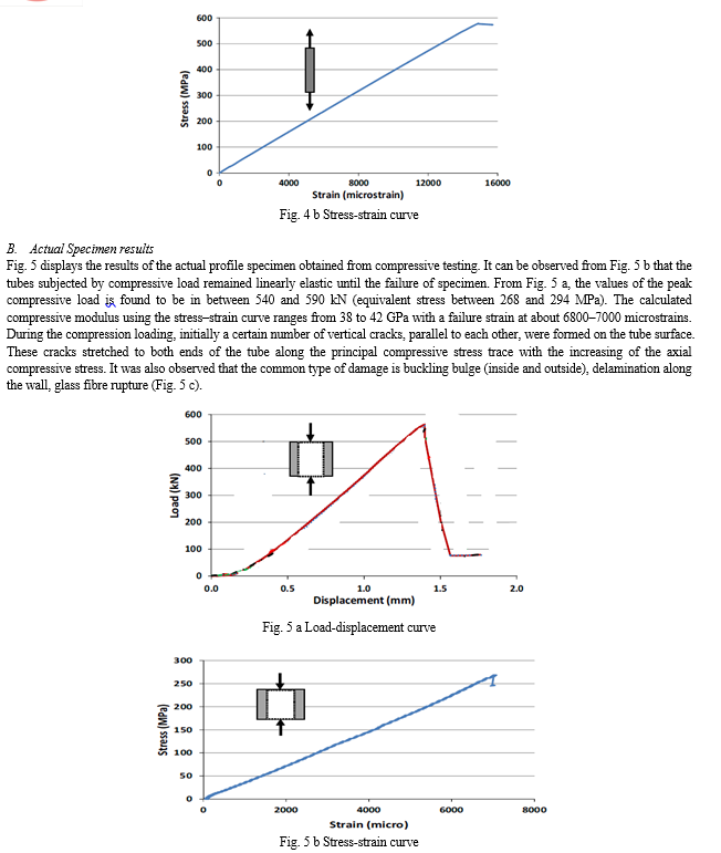
Table 2 summarise the average value of the properties of the composite tubes determined from actual profile tests. The results indicated in Table 2 show that for actual profile tests, the peak compressive stress of the full-scale specimen is 278 MPa. On the other hand, the compressive elastic modulus and strain at peak is 40 GPa and 0.69, respectively. From Table 2, the deviation of the experimental data derived from tests on actual profile specimen is less than 3%. The overall results from the experiment infer that the reproducibility of the test is quite reasonable and the manufacturing process of the tube is consistent.
Table 2 Summary of mechanical properties from actual specimen test
|
Properties |
Value |
|
Compressive, peak stress (MPa) |
278 |
|
Compressive, elastic modulus (MPa) |
40,000 |
|
Compressive, strain at peak (%) |
0.69 |
IV. SIMULATION USING ANSYS
A. Finite Element Analysis (FEA) Using ANSYS
Numerical simulations were performed to compare with the experimental measurements of the tensile and compressive behaviour of the tubes. The main objective of conducting the FE method in the characterisation of the tensile and compressive behaviours is to reduce the high cost brought by repeatedly conducting experimental works. [17] The finite element model was developed whereby the property inputs are based from the material properties derived from filament tests. Finite element method was conducted simulating the specimen and the loading set-up in the actual experimental conditions to have a reliable result. The simulation of the tensile and compressive behaviour of the actual profile tubes using FE analysis is discussed.
B. FE simulation on the Compressive Behaviour
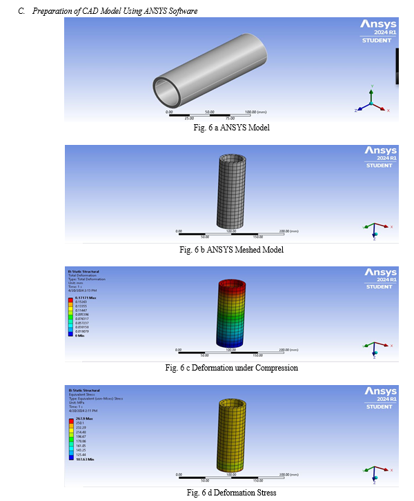
In this study, the 50 mm round tube with a length of 150 mm was modelled comprising 1248 nodes and 314 elements; with meshes of 5* 5 mm. Fig. 6 a shows the material model of the 50 mm round pultruded tube with a wall thickness of 5 mm and a length of 150 mm. Laminate properties were adopted as property attributes of plate elements. The laminate was modelled as a stack of several plies. [17] The ply properties adopted in modelling the laminate is summarised in Table 3.
Table 3 Material properties of the tube wall
|
Material property |
Symbol |
Property value |
Unit |
|
Density |
q |
1970 |
kg/m3 |
|
Thickness |
t |
0.5833 |
mm |
|
Elastic modulus (longitudinal direction) |
E11 |
39,200 |
MPa |
|
Elastic modulus (transverse direction) |
E22 |
12,900 |
MPa |
|
Poisson ratio |
µ |
0.35 |
- |
In the conducted experiment, the composite tube was in contact with stiff loading plates at the two ends. A uniformly distributed pressure was applied on the top of the model to properly simulate the loading condition. Initially, a 240 MPa uniform pressure load (equivalent to 510 kN) was applied on the top edge of the model. This value was chosen arbitrarily as this is more or less the peak load recorded during the experiment. [9] Fraction of this load was then used in the analysis to provide several load values in aid of plotting the load relationship. A linear static solver was used to investigate the compressive behaviour of the tube.
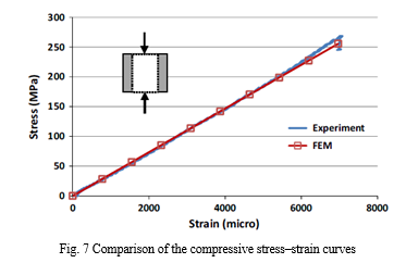
Fig. 7 displays the comparison of the longitudinal stress–strain curve obtained from the experimental and FE investigations. In the figure, the experimental data are from one of the tested specimen. The experimental result shows linear stress–strain relationship up to final failure and is in good agreement with the predicted stress– strain relation based from FE method. It should be noted that the failure in FE model assumed to adopt the strain at failure of the sample derived from test and used to calculate the stress at failure. The actual failure stress of the tube using experimental investigation is 278 MPa (equivalent to 550 kN failure) at a failure strain of 7000 microstrains. On the other hand, the predicted failure stress using FE method at same strain is around 267.9 MPa (512 kN). This value is 4.1% lower to that of the actual failure stress. The difference of the values is comparably small and therefore the values used in the inputs, as well as assumptions used in modelling, are considered acceptable as it predicts the experimental values reasonably.
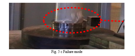
The comparison between the failure modes of the tube obtained from FE analysis is shown in Fig. 6 c. The typical failure mode observed in the experiment is buckling and at the sides of the tube. Moreover, delamination and matrix cracks at several locations of the tubes were present during the compressive test. The simulated failure of the tube reveals that bucking bulge happened at its outer diameter (Fig. 6 d). Similarly, bulging is also imminent at the sides of the tube. The experimental results show that cracking is also transpiring at the mid-length along the circumference of the tube. The simulated failure mode did not apparently have this kind of failure. However, it is clear that stress concentration in this area is highlighted indicating that cracks are imminent in this region.
Conclusion
In this mechanical characterization, tests were carried out on a round pultruded GFRP tube to investigate its mechanical properties. Moreover, an FE analysis was performed to simulate the compressive and flexural behaviours of the tube. The result showed that generally, specimen and actual specimen exhibited linearly elastic up to failure. Compared with the single tensile failure mode of GFRP tubes, two types of compressive failure modes, including micro-buckling and local buckling were observed. The maximum variation of the experimental data is around 6%. This also indicates that the experimental procedures were conducted within the acceptable margin of error. The comparison between the compressive peak load values using experiment and FE methods revealed that their difference is less than 5%. The tensile and compressive failure modes obtained from the experiment were fairly simulated in the FE analysis. These results showed that FE analysis predicted reasonably the actual tensile and compressive behaviours of the pultruded GFRP tube.
References
[1] Edwards KL., “An overview of the technology of fibre-reinforced plastics for design purposes,” pp. 1–10, 1998, Vol. 19(1-2). [2] Bakis CE, Bank LC, Brown VL, Cosenza E, Davalos JF, Lesko JJ, et al. “Fibrereinforced polymer composites for construction – state-of-the-art review”. J Compos Construct, pp. 73–87, 2002, Vol. 6(2). [3] Kumar P, Chandrashekhara K, Nanni A. “Structural performance of a FRP bridge deck”. Constr Build Mater, pp. 35–47. 2004, Vol. 18(1). [4] Guess TR, Reedy ED, Stavig ME. Characterisation of E-glass polyester woven fabric composite laminates and tubes. SANDIA REPORT: SAND95-2352 UC- 704; 1995. [5] “History of Composites - Composites 101,” CompositesLab. [6] Lubin, G. (1982). Handbook of Composites. New York: Van Nostrand Reinhold Company. [7] Mohammad Alhawamdeh, Omar Alajarmeh, Thiru Aravinthan, Tristan Shelley, Peter Schubel, Michael Kemp, Xuesen Zeng, “Modelling hollow pultruded FRP profiles under axial compression: Local buckling and progressive failure”, Composite Structures 262 (2021) pp.1-14. [8] Lining Ding, Xia Liu, Xin Wang, Hongjiao Huang, Zhishen Wu, “Mechanical properties of pultruded basalt fiber-reinforced polymer tube under axial tension and compression”, Elsevier.2018, pp. 1-18 [9] Farrukh Saghir, et. al. (2021), “Mechanical characterization of particulated FRP composite pipes: A comprehensive experimental study”, Polymer Testing 93 (2021), pp. 1-21. [10] Ernesto Guades, Thiru Aravinthan, “Residual properties of square FRP composite tubes subjected to repeated axial impact”, Composite Structures 95 (2013) pp. 354–365. [11] Chambers, R. E. (1997). ASCE Design Standard for Pultruded Fiber-Reinforced (FRP) Structures. Journal of Composites for Construction, pp. 26-38. [12] Hassan NK, Mosallam A S., “Buckling and ultimate failure of thin-walled pultruded composite columns”. Polym Compos 2004;12: pp. 469–81. [13] Regel F. “A modelling approach for 3D braid reinforced composites under non-axial”, loading PhD Thesis. University of Minho; 2014. [14] Pizhong Qiao, Guiping Zou. “Local buckling of composite fiber-reinforced plastic wide-flange sections”. J Struct Eng 2003;129:125–9. https://doi.org/10.1061/ (ASCE)0733-9445(2003)129:1(125). [15] Wang W, Sheikh MN, Hadi MNS. “Behaviour of perforated GFRP tubes under axial compression”. Thin Wall Struct 2015;95:88–100. https://doi.org/10.1016/j. tws.2015.06.019 [16] Buragohain MK. “Composite structures: Design, mechanics, analysis, manufacturing, and testing”. CRC Press; 2017. [17] Barbero EJ. “Finite element analysis of composite materials using AbaqusTM”. CRC Press; 2013. [18] Jagtap M.D., Gaikwad B.D. & Pawar P.M., “Stdy of roller conveyor chain strip under tensile loading”, IJMER, Vol. 4, 2014, pp. 2249-6645 [19] Wang X, Wu ZS. “Evaluation of FRP and hybrid FRP cables for super long-span cable-stayed bridges”. Composite Structures, 2010, 92(10):2582-2590. [20] Ba?inskas D, Rimkus A, Rumšys D, et al., “Structural Analysis of GFRP Truss Bridge Model”, Procedia Engineering, 2017, 172:68-74.
Copyright
Copyright © 2024 L. T. Mane, A. M. Tone, Prof. M. D. Jagtap. This is an open access article distributed under the Creative Commons Attribution License, which permits unrestricted use, distribution, and reproduction in any medium, provided the original work is properly cited.

Download Paper
Paper Id : IJRASET60748
Publish Date : 2024-04-22
ISSN : 2321-9653
Publisher Name : IJRASET
DOI Link : Click Here
 Submit Paper Online

