Ijraset Journal For Research in Applied Science and Engineering Technology
- Home / Ijraset
- On This Page
- Abstract
- Introduction
- Conclusion
- References
- Copyright
Mechanical Properties of Aluminium 5052- SiC MMC
Authors: Dr Ramakotaiah Maddumala
DOI Link: https://doi.org/10.22214/ijraset.2024.58181
Certificate: View Certificate
Abstract
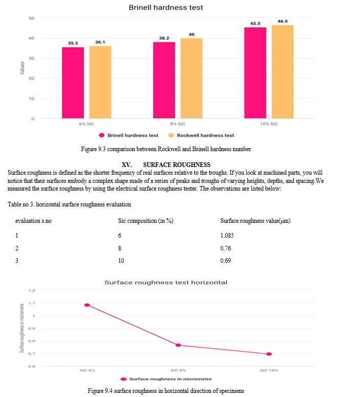
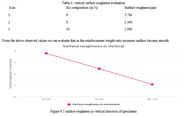
The metal matrix composites are mostly used in aerospace applications and in automobile sectors due to its light weight to strength ratio. Aluminium 5052 has been used as matrix and SiC as reinforcement. A liquid metallurgy route of stir casting technique was adapted to prepare cast composites. Taguchi method orthogonal array of L9 is used to design experiments. The weight fraction of Sic 6%, 8% and 10%, stirrer speed of 1400 rpm, reinforcement preheating temperature of 8000c is used. Hardness test, surface roughness test and microstructure evaluation tests were conducted on the specimens. The hardness improvement and micro structure are appreciable in 10% of SiC.
Introduction
I. INTRODUCTION
Aluminium is the world’s most abundant metal and is the third most common element, comprising 8% of the earth’s crust. The versatility of aluminium makes it the most widely used metal after steel. Although aluminium compounds have been used for thousands of years, aluminium metal was produced around 170 years ago. In the 100 years since the first industrial quantities of aluminium were produced, worldwide demand for aluminium has grown to around 29 million tons per year. About 22 million tons is new aluminium and 7 environmentally compelling. it takes 14000 kWh to produce 1 tonne of new aluminium. Conversely it takes only 5% of this to remelt and recycle one tonne of aluminium. There is no difference in quality between virgin and recycled aluminium alloys.
Pure aluminium is soft and ductile, and corrosion resistance and has a high electrical conductivity. It is widely used for foil and conductor cables, but alloying with other elements is necessary to provide the higher strengths for needed for other applications. Aluminium is one of the lightest engineering metals having strength to weight ratio superior to steel. By utilizing various combinations of its advantageous properties such as strength, lightness, corrosion resistance, recyclability and formability, aluminium is being employed in an ever-increasing number of applications. This array of product ranges from structural materials through to thin packaging foils.
- Strength To Weight Ratio: Aluminium has a density around one third that of steel and it is used advantageously in applications where high strength and low weight are required. This includes vehicles where low mass results in greater load capacity and reduced fuel consumption.
- Corrosion Resistance: When the surface of aluminium metal is exposed to air a protective oxidised coating form almost instantaneously. This oxide layer is corrosion resistance and can be further enhanced with surface treatment such as anodising.
- Electrical And Thermal Conductivity: Aluminium is an excellent conductor of the heat and electricity. There great advantage of aluminium is that by weight, the conductivity of aluminium is around twice that of copper. This means that aluminium is now the most commonly used material in large power transmission lines. The best alternative to copper is aluminium alloys in the thousand or six thousand series. This can be used for all conduction applications including domestic wiring. Weight considerations means that a large proportion of overhead, high voltage power lines now use aluminium rather than copper. They do however low strength and need to be reinforced with a galvanized or aluminium coated high tensile steel wire in each strand.
- Light And Heat Reflectivity: Aluminium is a good reflector of both visible light and heat making. It is a idle material for light fittings, thermal rescue blankets and architectural insulation's.
- Toxicity: Aluminium is not only nontoxic but also does not release any odour or taint products with which it is in contact this makes aluminium suitable for using packaging for sensitive products such as food or pharmaceuticals where aluminium foils is used.
II. APPLICATIONS
The properties of the various aluminium alloys as resulted in aluminium being used in industries as diverse as transport, food preparation, energy generation, packaging architecture, and electrical transmission applications. Depending upon the applications, aluminium can be used to replace other materials like copper steel zinc tin plate stainless steel titanium wood paper concrete and composites. Some examples of the areas where aluminium is used are given in the following sections packaging corrosion resistance and production against UV light combines with moisture and odour containment plus the fact that aluminium is non toxic and will not leach or taint the product that as resulted in the wide spread use of aluminium foils and sheet in food packaging and protection. The most common use of aluminium for packaging has been in aluminium beverage cans. Aluminium cans now count for around 50% of global consumption of aluminium. Transport after the very earliest days od manned flight the excellent strength to weight ratio of aluminium have made it the prime materials for the construction of air crafts. The same properties of aluminium mean various alloys are also now used in passenger and rail cars, commercial vehicles, military vehicles, ships and boats, buses and coaches, bicycles and increasingly motor cars. The sustainable nature of aluminium with regard to corrosion resistance and recyclability as helped drive the recent increase demand for aluminium vehicle component. Marine applications aluminium plate extractions are used extensively for the super structures of ships. The use of this materials allows designers to increase the above water line size of the vessel without creating stability problems. The weight advantage of aluminium as allowed marine architects to gain better performance from the available power by using aluminium in the hulls of hover craft, fast multihulled catamarans and surface planning results. Lower weight and longer life cycles have seen aluminium become the established material for helidecks and helideck support structures on offshore oil and gas rigs. The same reasons have resulted in the wide spread use of aluminium I oil rig stair towers and Telescopic personal bridges.
Building and architecture aluminium use in building covers a wide range of applications. The applications include roofing, foil insulation, windows, doors, shop fronts and architectural hardware and guttering. Aluminium is also commonly used as the in the form of trade plate and industrial flooring. Foils aluminium is produced in commercial foils as thick as 0.0065mm. material thicker than 0.2 mm is called sheet or strip. Aluminium foil is in previous to light gases, oils fats, volatile compounds and water vapour. These properties combined with high formability, heat and cold resistance, non-toxicity, strength in reflectivity to heat and light mean aluminium foil is used I any applications. These applications include pharmaceutical packaging, food protection and packaging, insulation, electrical shielding, lamination and other applications the above application accounts for approximate 85% of the aluminium consumed annually. The remaining 15% is used in wide variety of applications including ladders, high pressure gas cylinders, sporting goods, mechanized components, road barriers and science, furniture, lithographic printing plates.
III. INTRODUCTION TO STIR CASTING
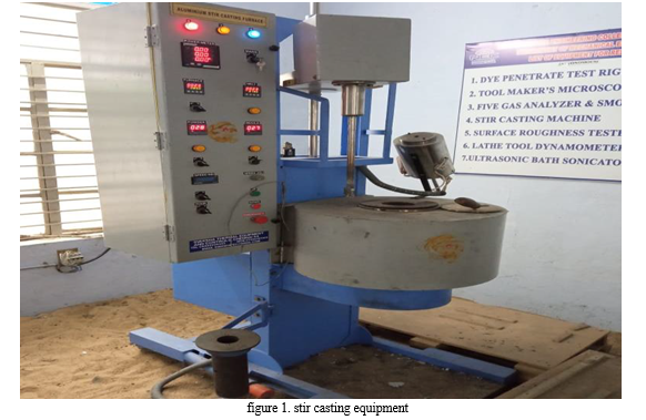
Stir casting is a type of casting process in which a mechanical stirrer is introduced to form vortex to mix reinforcement in the matrix material. It is a suitable process for production of metal matrix composites due to its cost effectiveness, applicability to mass production, simplicity, almost net shaping and easier control of composite structure Stir casting setup as shown in Figure 1, consist of a furnace, reinforcement feeder and mechanical stirrer. The furnace is used to heating and melting of the materials. The bottom poring furnace is more suitable for the stir casting as after stirring of the mixed slurry instant poring is required to avoid the settling of the solid particles in the bottom the crucible. The mechanical stirrer is used to form the vortex which leads the mixing of the reinforcement material which are introduced in the melt. Stirrer consist of the stirring rod and the impeller blade. The impeller blade may be of, various geometry and various number of blades. Flat blade with three number are the preferred as it leads to axial flow pattern in the crucible with less power consumption. This stirrer is connected to the variable speed motors, the rotation speed of the stirrer is controlled by the regulator attached with the motor. Further, the feeder is attached with the furnace and used to feed the reinforcement powder in the melt.
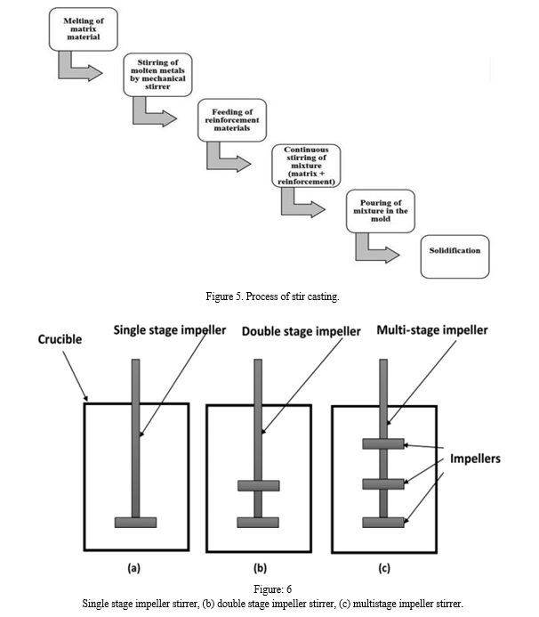
A permanent mold, sand mold or a lost-wax mold can be used for pouring the mixed slurry. Various steps involved in stir casting process is shown in Figure In this process, the matrix material is kept in the bottom pouring furnace for melting. Simultaneously, reinforcements are preheated in a different furnace at certain temperature to remove moisture, impurities etc. After melting the matrix material at certain temperature, the mechanical stirring is started to form vortex for certain time period then reinforcements particles are poured by the feeder provided in the setup at constant feed rate at the centre of the vortex, the stirring process is continued for certan time period after complete feeding of reinforcements particles. 6 Schematic of stir casting setup molten mixture is then poured in preheated mold and kept for natural cooling and solidification. Further, post casting process such as heat treatment, machining, testing, inspection etc. has been done.
There is various impeller blade geometry are available. Melting of the matrix material is very first step that has been done during this process.
IV. METAL MATRIX COMPOSITES (MMC)
A. Types Of MMC
Metal Matrix Composites is a combination of two or more components, i.e. matrix and reinforcing material. Usually, Metal matrix composites (MMCs) consist of a lowdensity metal, such as aluminium, magnesium, titanium, copper etc., reinforced with particulate or fibers of a ceramic material, such as silicon carbide or graphite. The most important MMC systems are: Aluminium matrix
- Continuous fibers: boron, silicon carbide, alumina, graphite
- Discontinuous fibers: alumina, alumina-silica
- Whiskers: silicon carbide
- Particulates: silicon carbide, boron carbide Magnesium matrix
- Continuous fibers: graphite, alumina
- Whiskers: silicon carbide
- Particulates: silicon carbide, boron carbide Titanium matrix
- Continuous fibers: silicon carbide, coated boron
- Particulates: titanium carbide Copper matrix
- Continuous fibers: graphite, silicon carbide
- Wires: niobium-titanium, niobium-tin
- Particulates: silicon carbide, boron carbide, titanium carbide. Superalloy matrices
- Wires:
Tungsten Matrix is the monolithic material and continuous in nature in which diverse materials are embedded in it. Reinforcements are added to the matrix to improve its properties like hardness, strength, elongation, conductivity, corrosion resistance etc.
Compared with unreinforced metals, MMCs offer higher specific strength and stiffness, higher operating temperature, and greater wear resistance, as well as the opportunity to tailor these properties for a particular application.
B. Manufacturing And Forming Process
Processing of metal matrix composites (MMC) can be classified into three main categories:
- Solid State Processing
- Liquid State Processing
- In-Situ Processing
a. State Processing: The main fabrication methods for solid state processing of metal matrix composites are powder blending and consolidation, and physical vapor deposition.
C. Powder Blending And Consolidation
Metal alloy powder is blended with ceramic whisker/short fiber/particles in dry condition or in liquid suspension. After blending, the mixture is further processed by cold compaction, canning, degassing, and high temperature consolidation. There are some oxide 10 particles in volume fraction of 0.05-0.5 depending on the powder and processing conditions that help dispersion- strengthening of the metal matrix composites. This method is usually used for the processing of aluminium and magnesium metal matrix composites.
D. Diffusion Bonding
The inter diffusion atoms at the metallic surfaces under pressure creates bonding between the metal matrix and fibers. This fabrication method is widely used for aluminium or magnesium MMCs reinforced with continuous/discontinuous fibers.
E. Physical Vapor Deposition
Fibers are continuously passed through a region of high partial pressure of metal to be deposited. The vapor is produced and inserted in the process, then the condensation occurs at this region to produce a coating on the fiber. The rate of deposition is about 5-10 micrometer per minute. The coated fibers are then consolidated by hot pressing or hot isostatic pressing.
V. LIQUID STATE PROCESSING
- Stir Casting: Particulate reinforcements are mixed with liquid metal melt and the mixture then solidifies. Specifically, the pre-treated particles are inserted into the vortex of molten alloy, which is created by a rotating impeller. A problem arises during the stir casting process as the reinforcements are not uniformly distributed and form sediments in the molten alloy. Generally, up to 30% particles in the size of 5-100 micrometer can be incorporated into the metal alloy. An example of this method is Al-(10-15%) B4C MMCs. In another variant of the stir casting method, particles are introduced into the metal alloy in the semisolid state.
- Squeeze Casting: Molten metal is introduced into an open die. The dies are then closed so that the molten metal solidifies under pressure within the dies. The heat is rapidly transferred from the molten metal to the dies under high pressure and through the contact between the metal and the die surface. As a result, a fine-grain casting with little to no pore is produced using this method.
- Infiltration Process: Liquid metal alloy is infiltrated into the porous forms of fibers/whiskers reinforcements. The volume fraction of the reinforcements usually ranges from 10- 70%, depending on the level of porosity. Silica and metal-based mixtures are often employed as binder to retain the integrity and shape of the porous forms.
- Spray Deposition: Particle/whisker/short fiber reinforcements are injected into the spray, creating a deposition layer of porosity of 5-10% on the metal surface. The depositions are then consolidated to full density by further processing. For continuous (long) fiber reinforced metal matrix composites, matrix metals are sprayed onto the fibers. The fiber spacing and fiber layer in this processing method impact the fiber volume fraction and distribution.
VI. HYBRID MATERIALS
Hybrid materials are composites consisting of two constituents at the nanometre or molecular level. Commonly one of these compounds is inorganic and the other one organic in nature.
Thus, they differ from traditional composites where the constituents are at the macroscopic (micrometre to millimetre) level. Mixing at the microscopic scale leads to a more homogeneous material that either show characteristics in between the two original phases or even new properties.
A. Introduction
Many natural materials consist of inorganic and organic building blocks distributed on the nanoscale. In most cases the inorganic part provides mechanical strength and an overall structure to the natural objects while the organic part delivers bonding between the inorganic building blocks and/or the soft tissue. Typical examples of such materials are bone, or nacre.
- Development Of Hybrid Materials
The first hybrid materials were the paints made from inorganic and organic components that were used thousands of years ago. Rubber is an example of the use of inorganic materials as fillers for organic polymers. The sol-gel process developed in the 1930s was one of the major driving forces what has become the broad field of inorganic-organic hybrid materials.
2. Classification
Hybrid materials can be classified based on the possible interactions connecting the inorganic and organic species. Class / hybrid materials are those that show weak interactions between the phases, such as Vander Waals, hydrogen bonding or weak electrostatic interactions. Class II hybrid materials are those that show strong chemical interactions between the components such as covalent bonds.
Structural properties can also be used to distinguish between various hybrid materials. An organic moiety containing a functional group that allows the attachment to an inorganic network, e.g., a tri alkoxysilane group, can act as a network modifier because in the final structure the inorganic network is only modified by the organic group. Phenyl tri alkoxysilanes are an example for such compounds; they modify the silica network in the sol-gel process via the reaction of the tri alkoxysilane group without supplying additional functional groups intended to undergo further chemical reactions to the material formed. If a reactive functional Group is incorporated the system is called a network functionalizer. The situation is different W two or three of such anchor groups modify an organic segment; this leads to materials in which the inorganic group is afterwards an integral part of the hybrid network. The latter type of system is known as network builder.
Blends are formed if no strong chemical interactions exist between the inorganic building blocks. One example for such a material is the combination of inorganic clusters or particles with organic polymers lacking a strong (e.g., covalent) interaction between the components. In this case a material is formed that consists for example of an organic polymer entrapped discrete inorganic moieties in which, depending on the functionalities of the components, for example weak crosslinking occurs by the entrapped inorganic units through physical interactions inorganic components are entrapped in a crosslinked polymer matrix. If an inorganic and an organic network interpenetrate each other without strong chemical interactions, so called interpenetrating networks (IPNS) are formed, which is for example the case if a sol-gel material is formed in presence of an organic polymer or vice versa. Both materials described belong to class I hybrids. Class II hybrids are formed when the discrete inorganic building blocks, e.g., clusters, are covalently bonded to the organic polymers or inorganic and organic polymers are covalently connected with each other.
B. Advantages Of Hybrid Materials Over Traditional Composites
Inorganic clusters or nanoparticles with specific optical, electronic or magnetic properties can be incorporated in organic polymer matrices. Contrary to pure solid state inorganic materials that often require a high temperature treatment for their processing, hybrid materials show a more polymer-like handling, either because of their large organic content or because of the formation of crosslinked inorganic networks from small molecular precursors just like in polymerization reactions. Light scattering in homogeneous hybrid material can be avoided and therefore optical nanocomposites can be achieved.
VII. MECHANICAL TESTING
Mechanical testing reveals the properties of a material under dynamic or static force. Designed to ensure that materials are suitable for their intended applications, mechanical testing includes methods such as tensile strength and elongation, compression strength, impact resistance, fracture toughness, stress rupture, fatigue limits, hardness, and more.There exist a large number of tests, many of which are standardized, to determine mechanical properties of materials.
In general, such tests set out to obtain geometry independent properties i.e., those intrinsic to the bulk material. In practice this is not always feasible, since even in tensile tests, certain properties can be influenced by specimen size and/or geometry. Here is a listing of some of the most common tests:
A. Hardness Testing
Vickers hardness test (HV), which has one of the widest scales
Brinell hardness test (HB)
Knoop hardness test (HK), for measurement over small areas
Janka hardness test, for wood
Rockwell hardness test (HR), principally used in the USA
Shore durometer hardness, used for polymers
B. Meyer hardness test
Barcol hardness test, for composite materials. Tensile testing used to obtain the stress-strain curve for a material, and from there, properties such as young’s modulus, yield (or proof) stress, tensile stress and % elongation to failure.
? Impact testing
C. Izod test
Charpy test.
Fracture toughness testing
Linear-elastic (Kic)
K-R curve
Elastic plastic (Jic, CTOD)
Creep Testing, for the mechanical behaviour of materials at high temperatures (relative to their melting point)
Fatigue Testing, for the behaviour of materials under cyclic loading.
Load-controlled smooth specimen tests
Strain-controlled smooth specimen tests
Fatigue crack growth testing.
•Non-Destructive Testing
D. Surface Roughness Testing
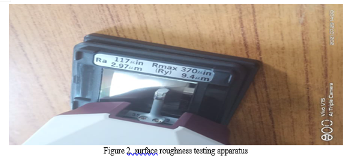
Surface roughness, often shortened to roughness, is a component of surface texture. It is quantified by the deviations in the direction of the normal vector of a real surface from its ideal form. If these deviations are large, the surface is rough; if they are small, the surface is smooth. In surface metrology, roughness is typically considered to be the high-frequency, short-wavelength component of a measured surface. However, in practice it is often necessary to know both the amplitude and frequency to ensure that a surface is fit for a purpose. Roughness plays an important role in determining how a real object will interact with its environment. In tribology, rough surfaces usually wear more quickly and have higher friction coefficients than smooth surfaces. Roughness is often a good predictor of the 20 performance of a mechanical component, since irregularities on the surface may form nucleation sites for cracks or corrosion. On the other hand, roughness may promote adhesion. Generally speaking, rather than scale specific descriptors, cross-scale descriptors such as surface fractality provide more meaningful predictions of mechanical interactions at surfaces including contact stiffness and static friction. Although a high roughness value is often undesirable, it can be difficult and expensive to control in manufacturing. For example, it is difficult and expensive to control surface roughness of fused deposition modelling (FDM) manufactured parts.[3] Decreasing the roughness of a surface usually increases its manufacturing cost. This often results in a trade-off between the manufacturing cost of a component and its performance in application.
Roughness can be measured by manual comparison against a "surface roughness comparator" (a sample of known surface roughness), but more generally a surface profile measurement is made with a profilometer. These can be of the contact variety (typically a diamond stylus) or optical (e.g.: a white light interferometer or laser scanning confocal microscope.
However, controlled roughness can often be desirable. For example, a gloss surface can be too shiny to the eye and too slippery to the finger (a touchpad is a good example) so a controlled roughness is required. This is a case where both amplitude and frequency are very important.
VIII. LITERATURE REVIEW
This chapter presents a review of the literature data available on the effect of various reinforcement types, their size and volume fraction, ageing behaviour with AL based MMC’s
Dattatraya N et.al, [1] presents a study on stir casing process and process parameter having Al alloy as a matrix phase and alumina (Al2O3) as a reinforcement. In their study, they have concluded the following points: (i) Stir casing process can successfully be used for manufacturing of AMMC’s having low density and enhanced mechanical properties. 2) Stir casting process is cost effective and conventional route for manufacturing of composite material. 3) Material having isotropic nature can be manufactured successfully. 4) Preheating of mould reduces porosity and enhances mechanical properties. 5) Addition of Magnesium is important to increase wettability. 6) Design of stirrer decides the flow pattern of melt. 7) Stirrer speed, stirring time decides quality of casting. 8) Preheat temperature of mould, preheat temperature of reinforcement, reinforcement size, reinforcement feed rate and melt pouring rate are also the important parameters in stir casting method.
Manikandan. C, [2] noticed in his experimental study, that the 12% of SiC and 450°C preheat temperature of the reinforcement improves the hardness and impact strength of the composite. At 6% of SiC, 200 rpm of stirrer speed and 500°C reinforcement pre heat temperature attains the improved level of tensile strength. The hardness and impact strength to values are directly proportional to the SiC composition rate. the minimal percentage of elongation is obtained in the 9% of SiC, 250 RPM and 500 °C pre heating temperature of reinforcement.
Hariharan. R et.al, [3] carried out the research work by fabricating Al6061 – TiB2 MMC by stir casting method. The addition of the TiB particles into Al-6061 is a good route to improve the mechanical properties of materials. The resulting composite showed the increase in tensile strength when compared to the unreinforced alloy. SEM and XRD analysis of the composite confirms the presence of TiB particle and its volume fraction. The increased volume fraction of the TiB particles contributed to increase the strength of composites. The dry sliding at room temperature shows that there is a definite increase in the wear resistance of Al6061 alloy by the addition of TiB2 particles.
Pradeep R et.al [4] observed the study of mechanical properties of Al- Red Mud and Silicon Carbide Metal Matrix Composite (MMC) of Aluminium alloy of grade 5052 with addition of 22 varying weight percentage composition such as SiC8%+Al5052, SiC6%+Red mud2%+ Al5052, SiC4%+Red mud 4%+Al5052, SiC2%+Red mud 6%+Al5052, Red mud 8%+Al5052ed mud and Silicon Carbide particles by stir casting technique. The experimental result reveals that the combination of a matrix material with reinforcement such as SiC and Red mud particles, improves mechanical properties like tensile strength, compressive strength, hardness and yield strength.
Hossein Abdi Zadeh et.al [5] fabricated AMMC reinforced with nano Mgo (1.5, 2.5 and 5 vol%) by stir casting and powder metallurgy methods. During fabrication of AMMC Processing temperature of 800, 850 and 9500 c for stir casting and 575, 600 and 6250 c for powder metallurgy have been considered. and mechanical properties are investigated. Al- nano Mgo composite exhibited high hardness values for 5 vol % of Mgo and better mechanical properties were observed at 625 and 8500 c for powder metallurgy and stir casting respectively.
L. Rasidhar et.al [6] casted Aluminium ilmenite nano composite via stir casting technique having 1 to 5 weight percentage of ilmenite. During fabrication, molten metal (8500C) is stirred for 10-15 min with rpm 650 to 700. To minimize the oxidation of molten aluminium, argon gas is supplied in the crucible. The increase in tensile and hardness values was observed with increase in reinforcement. Tensile and hardness values were maximum at 5% wt of ilmenite reinforcement.
Mahendraboopathi .M et.al. [7] fabricated Al2024 reinforced with silicon carbide and fly ash hybrid metal matrix composites by two-step stir casting process. The optical micrographs revealed that distribution of SiC and fly ash particles were uniform in aluminium metal matrix composite. The author observed that increase in wt fraction of reinforcement, tensile strength, yield strength and hardness of the composite will also increase. It is also concluded by the author that if the percentage of SiC and fly ash is increased then the rate of elongation of the hybrid MMCs is decreased significantly.
Manoj Singla et.al [8] fabricated aluminium (98.41% C.P) based silicon carbide (320-grit) particulate metal matrix composite the two step stir casting technique. Reinforcement of SiC was 5, 10, 15, 20, 25, and 30% by weight. During fabrication, all other parameters were kept constant. Authors observed that at 25% wt fraction of SiC reinforcement, maximum hardness and maximum impact strength was obtained.
Velmurugan et al [9] manufactured Al 6061- SiC/Graphite hybrid composite by stir casting technique with graphite stirrer. Fabrication of AMMC is carried out with10 wt% of SiC and 23 4wt% of graphite particles. Authors observed that wear resistance and brittleness are improved with the addition of SiC particles while addition of graphite particles improves the surface finish because they act as a solid lubricant. That is why heat generation during machining is reduced.
Sourav Kayal et.al [10] fabricated Aluminium alloy (LM-6)- SiC p composite by stir casting method. During fabrication of AMMCs, weight percentage of SiC was varied 2.5, 5, 7.5, 10, 12.5, and 15%. From SEM images uniform distribution of SiC particles in the composite samples were observed. Authors also observed that with increase in the fraction of SiC p, hardness was also increased.
V. Ramakoteswara Rao et.al. [11] produced Al 5052 and TiC metal matrix composite by stir casting route. In this fabrication reinforcement percentage of TiC was 2 to 10% by wt. Authors observed that if reinforcement particulates (TiC) percentage was increased, hardness was also increased.
Rama Rao et.al. [12] fabricated aluminium-boron carbide composites by stir casting techniques with different particulate weight fractions (2.5, 5 and 7.5%). The authors observed that distribution of the boron carbide particles in the samples were uniform. Tensile strength and hardness of the composite increased while density was decreased with increasing the amount of the boron carbide in the AMMC.
Ravichandran M et.al [13] carried out the research work by fabricating aluminium metal matrix composites through liquid powder metallurgy route. The aluminium matrix composite containing TiO2 reinforcement particle was produced to study the mechanical properties such as tensile strength and hardness. The characterization studies are also carried out to evident the phase presence in the composite and the results are discussed for the reinforcement addition with the mechanical properties. Results show that, the addition of 5 weight percentage of TiO2to the pure aluminium improves the mechanical properties.
- Izadi et.al [14] investigated through FSP and has observed improvement in the micro hardness of Al–SiC composites produced by traditional powder metallurgy and sintering methods. The material flow in the stir zone during FSP was successful in uniformly distributing the SiC particles. However, when samples with 16% SiC (by volume) were processed, there were residual pores and lack of consolidation. An increase in hardness of all samples was observed after friction stir processing which was attributed to the improvement in particle distribution and elimination of porosity.
[6] Keshavamurthy R et.al studied about Al5052-TiB2 insitu composite, processed by stir casting technique using commercially available Al-10%Ti and Al- 3%Br master alloys. Both matrix alloy and composite were subjected to microstructure analysis, micro hardness test, grain size studies and tensile test.
Microstructure shows fairly uniform distribution of TiB2 particles in matrix alloy. Average grain size of the composite was lower than unreinforced alloy. Micro hardness, yield strength and ultimate tensile strength of Al5052-TiB2 composite, were considerably higher when compared with unreinforced alloy.
Uvaraja et.al observed that Hybridization is commonly used for improving the properties and for lowering the cost of conventional composites. Hybrid MMCs are made by dispersing two or more reinforcing materials into a metal matrix. They have received considerable research and trials by Toyota Motor Inc., in the early 1980s. Hybrid metal matrix composites are a relatively new class of materials characterized by lighter weight, greater strength, high wear resistance, good fatigue properties and dimensional stability at elevated temperatures than those of conventional composites
IX. STIR CASTING FOR AL 5052 ALLOY STIR CASTING ROUTE FOR FABRICATION OF MMC PREPARATION OF CASTING
The base material used is Al5052 alloy. The required amount of Al 5052 alloy was placed in crucible in an electric heating furnace to a temperature of about 750-800 0 C maintained. The stirrer was carefully placed at a required depth in the crucible and stirred at 1400 rpm to form a vortex. The reinforcement material added in to vertex and stirred for about 25 to 30 min to obtain a homogenous mixture. The molten mixture carefully poured into the moulds box to obtain the castings, which are later allowed to cool and checked for any defects in the castings. Further samples were prepared as per the ASTM standards for the evaluation of mechanical properties of proposed composites. Stir casting furnace After it is cooled down to temperature between liquid and solidus state means it is in a semi-solid state.
Then preheated reinforcement particles are added to molten matrix and again heated to fully liquid state and are stirred thoroughly for a homogeneous mixture with the matrix alloy. In this method, the particles get accumulated often; the accumulated particles can be dissolved at higher temperature by vigorous stirring. The liquid composite materials are then poured into the sand/die casting mould and then allowed to solidify. Stir casting is suitable for manufacturing composites with up to 30% volume fractions of reinforcement. A major concern in associated with the stir casting is segregation of reinforcement particles due to various process parameters and material properties result in the non- homogeneous metal distribution. the preheated mixture in molten metal Stirring is done for 3 - 4 min Molten Metal (MMC’s) is poured into the die Stir casting technique implemented Varying process parameters done Cast the solid component Samples are prepared Specimen preparation as per the ASTM standards Metallurgical & Mechanical properties of MMC (Microstructure, SEM, Hardness, Tensile).
X. METHODOLOGY
- First of all, we collect the data of topic which we are working
- We select appropriate reinforcement materials i.e., SiC based on its mechanical properties
- Now, we select appropriate concentration of the reinforcement material.
- We select the type of casting techniques and make a pattern according to the required dimensions
- The dimensions of pattern are as follows
Length of the pattern – 120 mm
Width of the pattern – 20mm
Height of the pattern – 10 mm
6. The mould is made by using sand casting techniques
7. The Al 5052 rods are melted inside a reverberatory furnace at 750°c
8. Different concentrations of SiC powder is added to the molten metal and is stirred for sufficient time
9. After stir casting the metal is casted
10. The molten metal is allowed to cooled down and later subjected to heat treatment process
11. After heat treatment, the MMC is subjected to various operations like cutting, grinding for making specimen in required dimensions
12. After cutting and grinding, the MMC is subjected to various finishing operations and finally, specimen is created
13. After making the specimen, it is subjected to different testings.
14. After hardness test, structural evaluation and surface roughness testing the mechanical properties are calculated and compared with parent metal.
15. Finally, the project is ready.
XI. MATERIAL SELECTION AND MAKING OF AL 5052 SiC COMPOSITE
A. Selection Of Base Material
Pure aluminium matrix on mechanical properties of stir casting of aluminium composite materials reinforced with silica carbide particles using simple foundry melting alloying and casting route. The experimental results indicate that aluminium matrix cast composite be manufactured via conventional foundry method giving very good responses to the strength and ductility up to 10% in aluminium matrix. The properties of aluminium include low density and therefore low weight, high strength, superior malleability, easy machining. excellent corrosion resistance and good thermal and electrical conductivity are amongst aluminium's most important properties.
Aluminium metal matrix composite consists of silica carbide of 6%, 8%, 10% (by weight). The presence of silica improves machinability and increases the brittleness of the MMC.
B. Selection Of Silica Carbide Powder
Silica carbide is directly available in powder form in market in different grit sizes. The silica carbide is directly purchased from the market of required grit size. It is then heated to remove the impurities. It is then filtered so that proper grain size is available.
C. Preparation Of Die
soap surfaces of the die which will be in contact with the molten metal to be cast. The applied die is then allowed to be dried and must be free from moisture during casting process for this the die is usually preheated by placing the die in the oven for about 3-5 minutes.
D. Preparation Of Work Piece By Stir Casting
Preparation of Casting: The base material used is Al5052 alloy. The required amount of Al 5052 alloy was placed in crucible in an electric heating furnace to a temperature of about 750-800o C maintained. The stirrer was carefully placed at a required depth in the crucible and stirred at 1400 rpm to form a vortex. The reinforcement material added in to vertex and stirred for about 25 to 30 min to obtain a homogenous mixture. The molten mixture carefully poured into the moulds box to obtain the castings, which are later allowed to cool and checked for any defects in the castings. Further samples were prepared as per the ASTM standards for the evaluation of mechanical properties of proposed composites. Stir casting furnace After it is cooled down to temperature between liquid and solidus state means it is in a semi-solid state.
Then preheated reinforcement particles are added to molten matrix and again heated to fully liquid state and are stirred thoroughly for a homogeneous mixture with the matrix alloy. In this method, the particles get accumulated often; the accumulated particles can be dissolved at higher temperature by vigorous stirring. The liquid composite materials are then poured into the sand/die casting mould and then allowed to solidify. Stir casting is suitable for manufacturing composites with up to 30% volume fractions of reinforcement. A major concern in associated with the stir casting is segregation of reinforcement particles due to various process parameters and material properties result in the non- homogeneous metal distribution. the preheated mixture in molten metal Stirring is done for 3 - 4 min Molten Metal (MMC’s) is poured into the die Stir casting technique implemented Varying process parameters done Cast the solid component Samples are prepared Specimen preparation as per the ASTM standards Metallurgical & Mechanical properties of MMC (Microstructure, SEM, Hardness, Tensile).
E. Preparation Of Specimen By Machining
The casted work pieces are then machined by kuding them in the head stock spindle of the lathe and fixing rigidly in the 3-jaw chuck and HSS (high speed steel) is employed for machining process. Firstly, the facing operation is performed by adjusting the single point cutting tool (HSS) position so that it contacts the work piece at the centre and the tool is fixed rigidly at an angle of 45 degrees and by giving longitudinal feed so that the tip of the tool contacts the work piece and by giving cross feed till the tool reaches and removes the material at the centre of the work piece. Then the work piece is unloaded from the head stock spindle and similarly the facing operation is performed on the other end of the work piece Then remove the dead centre from the quill of the tail stock and place the drill chuck in the quill and tighten it and perform drilling operation on the right end of the work piece by rotating the hand wheel to appropriate depth. The drill chuck is then removed from the quill of the tail stock and the dead centre is placed and tightened in the tail stock and by rotating the hand wheel of the tail stock such that the tip of the dead centre inserts into the drilled hole for supporting the other end of the work piece. The plane turning operation is then performed on the work piece throughout its length by adjusting the cutting tool position at an inclined position to the work piece and giving less depth of cut and slow feed.
- Preparation Of Microstructure Specimen
The micro structure specimen is prepared by machining the work piece on the lathe by doing the facing operation on the work piece at both of its ends and the dimensions are marked over the work piece the length of the specimen should be usually about 20mm to 40mm with a sufficient diameter having a minimum limit of 10mm.
The plane turning operation is on the work piece over its entire length by giving less depth of cut and slower feed rates then the depth of cut is gradually given until the diameter of the work piece is reduced to 10mm. Then hack sawing operation is performed by cutting work piece with hack saw by applying water as coolant to the blade to obtain the length of 20mm and again the facing operation is performed at the end. After performing the machining operation of the work piece as per the specified dimensions the specimen for the micro structure is obtained and finally surface finishing operation is performed with the help of an emery paper of grain sizes 150 and 120 microns respectively for obtaining fine surface finish of the specimen. The same above procedure is employed for the preparation of other specimens of different micron sizes.
XII. FACTORS EFFECTING AL 5052 SIC COMPOSITE
A. Melting Of Matrix Material
Out of various furnaces, bottom pouring furnace is suitable for fabrication of metal matrix composites in stir casting route, this type of furnace consists of automatic bottom pouring technique which provides instant pouring of the melt mix (matrix and reinforcement). Automatic bottom pouring is mainly used in investment casting industry. In this technique, a hole is created in the base of melting crucible to provide bottom pouring and was shielded by a cylinder-shaped shell of metals in stir casting process, the matrix material is melted and maintained a certain temperature for 2–3 h in this furnace. Simultaneously, reinforcements are preheated in a different furnace. After melting of the matrix material, the stirring process has been started to form the vortex.
B. Mechanical Stirring
In stir casting process, the mechanical stirrer is coupled with the varying speed motor to control the speed of the stirrer. There are various stages of impeller stirrer i.e., single stage, double stage and multistage impeller. Double stage and multi stage stirrer is mainly used in chemical industries whereas single stage impeller stirrer is commonly used for fabrication of AMCs and HAMCs due flexibility and to avoid excessive vortex flow Figure shows various stages of impeller stirrer.

Stirring plays a vital role over the final microstructure and mechanical properties of the casted composites as it controls the distribution of reinforcements within the matrix. Optimum mechanical properties can be attained by the uniform distribution of reinforcement and this problem is a common to most of processing techniques, including stir casting This problem can be solved by optimal selection of stirring parameters
XIII. MECHANICAL TESTING AND MICROSTRUCTURAL EVALUATION
Hardness Test
The Brinell hardness test method is used to determine Brinell hardness and is defined in ASTM E10. Most commonly it is used to test materials that have a structure that is too coarse or that have a surface that is too rough to be tested using another test method, e.g., castings and forgings. Brinell testing often use a very high-test load (3000 kg-f) and a 10mm wide indenter so that the resulting indentation averages outmost surface and sub-surface inconsistencies. The Brinell method applies a predetermined test load to a carbide ball of used diameter which is held for a predetermined time period and then removed. The resulting impression is measured across at least two diameters usually at right angle to each other and these results are averaged. A chart is then used to convert the averaged diameter measurement to Brinell hardness number. Test forces range from 500 to 3000 kg-f
A. Micro Structure Evaluation
SAMPLE PREPARATION
In order to identify and evaluate the microstructure of material, it is very important to prepare the test sample carefully and properly. The various steps in sample preparation for microstructural examination include:
- Selecting a representative sample of the materials
- Sectioning the sample to avoid altering or destroying the structure of interest
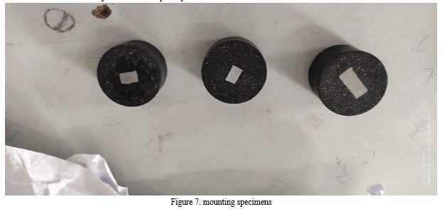
- Mounting the section without damage to the test sample.
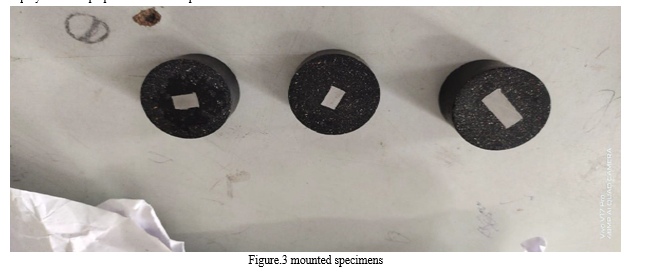
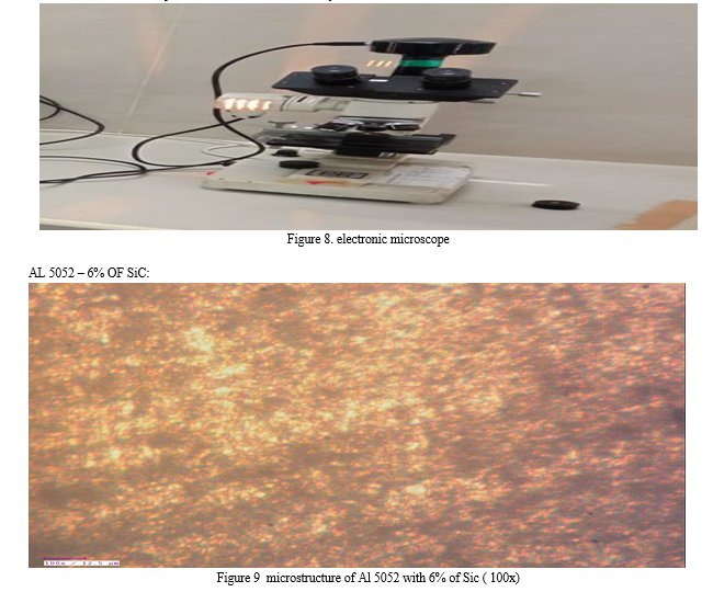
Grinding to achieve a flat sample with a minimum amount of damage to the sample surface Polishing the mounted and ground sample Etching in the proper etchant to reveal the microstructural details. The Metallographic specimens were prepared by mounting and grinding and polishing by using aluminium oxide powder, diamond paste and etched with keller's reagent. Micro structural observations were carried out by employing optical microscope of the cross-section’s perpendicular to the tool transverse direction. Micro structural observations were carried out at 400X by optical microscope. Examination of the microstructure of a material provides information used to determine if the structural parameters are within certain specifications. Microstructural examination is generally performed using optical or scanning electron microscopes to magnify features of the material under analysis. The amount or size of these features can be measured and quantified, and compared to acceptance criteria. These examinations are often used in failure analysis to help identify the type of material in question and determine if the material received the proper processing treatments. Metallurgical examinations may evaluate:
? Extent of decarburization and carburization, grain size, intergranular attack of corrosion Depth of alpha case in titanium alloys
? Percent spheroidization
? Inclusion ratings
? Volume fraction of various phases or second phase particles in metals.
XIV. RESULTS AND CONCLUSION
A. Micro Structural Evaluation
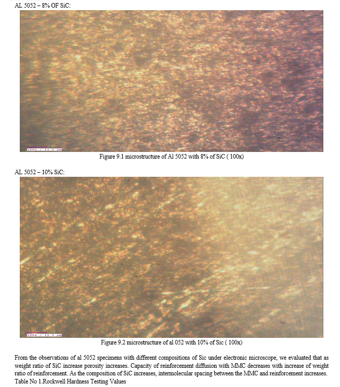
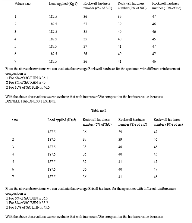
Optical Metallurgical microscope is used to study the distribution of silicon carbide inside the aluminium matrix. Average size of the aluminium particles visualized is 100 μm. It is observed that the distribution of ceramic particles inside the matrix of aluminium is uniform over the matrix, which is maintained by constant stirring the melt and the uniformity is verified in the microstructure. It is to be noted that the ceramic particles appear black against a bright background. Further, the distribution of aluminium particles is more even.
In order to make the crystal structure visible, the sample surface must be initially ground even and then polished. After completion of the last polishing step, first predictions about the purity of the material can be ascertained through the different reflexions. In order to make crystal structure visible for being contrasted. If the crystalline structure contrasts correctly in this manner, then the sample can be evaluated if and when a hardness test is to be performed (micro and universal hardness tester) then all common –phase test procedure. In the present work, research on the SEM examination of Al5052 alloy and its nanocomposites produced under optimum conditions mentioned above show that distribution of reinforcement particles is homogeneous; reactions on the Al 5052/ Sic matrix interface are not observed. The mechanical behaviour of the composites increases with increasing wt. % of nano (Al5052 + SiC) when compared with the unreinforced alloy.
Conclusion
Now a days challenges in the fabrication of metal matrix composite are growing vigorously. In this paper the method for the manufacturing of Al5052 by various research are discussed from discussion discovers the importance of the selection of the stirring parameters over the properties of the stir casted composite desired for current demand of the industries. This review has investigated the effect and optimization of stirring parameters. The range of stirring speed may vary depending upon the properties of the reinforcements and matrix mat-erisal, wettability and chemical properties from 1200 to 1400,1600 rpm. Also, it is concluded that Impeller Blade angle at 300angle gives optimal value, which will provide suitable combination axial flow and shearing action with lower power consumption. Position of the impeller should be kept at more the 25–30% of the height of the liquid from bottom the crucible. Optimal stirring time of 10 min is suggested. Diameter of the impeller should in the range of 50–55% of the diameter of the crucible and reinforcement federate, as in the range of 0.8–1.5 g/s-
References
[1] Dattatraya N. Lawate Shriyash S. Shinde Tushar S. Jagtap: Study of process parameters in stir casting method for production of particulate composite plate, International Journal of Innovations in Engineering Research and Technology, Volume 3, Issue 1, 2016. [2] Manikandan.C: Experimental Investigation on Mechanical Behavior’s of Stir Cast Aluminium 6061-SiC MMC using Taguchi Technique, International Research Journal of Engineering and Technology, Volume 04. Issue 04, 2017. [3] R. Hariharan and R.J. Golden Renjith Nimal: Experimental Investigations on Material Characteristics of Al 6061- TiB2 MMC Processed by Stir Casting Route, Middle-East Journal of Scientific Research, Volume 12, Issue 12, ( 1615-1619), 2012. [4] Pradeep, R., Praveen Kumar, B.S and Prashanth: Evaluation of mechanical properties of aluminium alloy 5052 reinforced with silicon carbide and red mud composite, International Journal of Engineering Research and General Science, Vol. 2, Issue 6, (1081-88), 2014. [5] Hossein Abdizadeh, Reza Ebrahimifard, Mohammad Amin Baghchesara, Investigation of microstructure and mechanical properties of nano MgO reinforced Al composites manufactured by stir casting and powder metallurgy methods: A comparative study, Composites: Part B 56 (2014) 217–221. [6] L. Rasidhar, Dr. A. Rama Krishna and Dr. Ch. Srinivas Rao, Fabrication and Investigation on Properties of Ilmenite (FeTiO3) based Al-Nanocomposite by Stir Casting Process, International Journal of Bio-Science and Bio-Technology Vol. 5, N o. 4, August, 2013. [7] M.Mahendra boopathi, K.P. Arulshri N. Iyandurai, “ Evaluation of mechanical properties of aluminum alloy 2024 reinforced with silicon carbide and fly ash metal matrix composites”, American journal of applied sciences, 10, 2013, 219-229 . [8] Manoj Singla, D. Deepak Dwivedi, Lakhvir Singh, Vikas Chawla, Development of Aluminium Based Silicon Carbide Particulate Metal Matrix Composite Journal of Minerals & Materials Characterization & Engineering, Vol. 8, No.6, pp 455-467, 2009. [9] Velmurugan C, Subramanian R, Thirugnanam S & Ananadavel B. Experimental investigations on machining characteristics of Al 6061 hybrid metal matrix composites 49 processed by electrical discharge machining. International Journal of Engineering, Science and Technology, 3(8) 87- 101, 2011 [10] Sourav Kayal , Behera. R, Nandi. T, Sutradhar. G, Solidification behavior of stircast Al alloy metal matrix composites, International Journal of Applied Engineering Research, dindigul, Volume 2, No 2, 2011. [11] Ramakoteswara Rao.V., Ramanaiah.N., and Sarcar.M.M.M., “Fabrication and investigation on Properties of TiC reinforced Al5052 metal matrix composites”, Applied Mechanics and Materials, 592-594 ,2014, 349-353. [12] S.Rama rao, G. Padmanabhan, “Fabrication and mechanical properties of aluminium-boron carbide composites”, international journal of materials and biomaterials applications, 2, 2012, 15-18. [13] Ravichandran, M. and Dineshkumar, S.: Synthesis of AlTiO2 Composites through Liquid Powder Metallurgy Route,International Journal of Mechanical Engineering, Vol. 1 Issue 1, 2014. [14] Izadia, H., Noltingb, A. et.al: Friction stir processing of Al/SiC composites fabricated by powder metallurgy, Journal of Materials Processing Technology, 1900– 1907, 2013 [15] Keshavamurthy, R., Sadananda Mageri, et.al: Microstructure and Mechanical Properties of Al5052–TiB2 in–situ composite, Research Journal of Material Sciences, Vol. 1(10), (6-10), 2013.
Copyright
Copyright © 2024 Dr Ramakotaiah Maddumala. This is an open access article distributed under the Creative Commons Attribution License, which permits unrestricted use, distribution, and reproduction in any medium, provided the original work is properly cited.

Download Paper
Paper Id : IJRASET58181
Publish Date : 2024-01-25
ISSN : 2321-9653
Publisher Name : IJRASET
DOI Link : Click Here
 Submit Paper Online

