

Ijraset Journal For Research in Applied Science and Engineering Technology
Detection of Microcalcifications with Vessels, Using Linear Structure Analysis and Uncertainty Tracking Technique in Mammography
Authors: Preethi M, Rukmini Bhat, Reshma
DOI Link: https://doi.org/10.22214/ijraset.2024.66003
Certificate: View Certificate
Abstract
As a potential biomarker for women’s cardiovascular and chronic kidney diseases, breast arterial calcification (BAC) in mammography has become an emerging research topic in recent years. To provide a more objective measurement for vascular structures with calcium depositions in mammography, this paper introduces a new computerized method to delineate calcified vessels. Specifically, we leverage two underlying cues—calcification and vesselness—within a multiple seeded tracking with uncertainty scheme. This new vessel-tracking scheme generates numerous sampling paths to describe the complicated topology of vascular structures with calcium depositions. A compiling and linking process is further employed to organize these sampling paths into vessel segments that are likely part of the same vessel tract. The proposed method has been evaluated on 63 mammograms, comparing manual delineations from two experts using various assessment metrics. The experimental results confirm the efficacy and stability of the proposed method, indicating its potential use as a convenient BAC measurement tool, replacing the trivial and tedious manual delineation tasks.
Introduction
I. INTRODUCTION
BREAST arterial calcification (BAC) is a phenomenon of calcium deposition along the vascular lumen in breast.
A. Micro Calcification
Calcification of soft tissue (arteries, cartilage, heart valves, etc.) can be caused by Vitamin K deficiency or by poor calcium absorption due to a high calcium/vitamin D ratio. This can occur with or without a mineral imbalance. Mammography, which is an x-ray examination of the breast, can be categorized into two types: screening mammography and diagnostic mammography. Screening mammography detects breast disease in women who do not have any symptoms, whereas diagnostic mammography is used to help make a diagnosis in women who have breast complaints such as a lump or an abnormality that was discovered during a screening mammogram.
1) Non-Cancerous Causes Of Calcifications
There are many non-cancerous causes of calcium in the breast including:
- Fibro adenoma - a non-cancerous growth that degenerates over time leaving behind large, chunky deposits of calcium that can look like popcorn (see Figure 2).
- Scar tissue in the breast - calcium can be deposited in scar tissue after, for instance, a surgical biopsy (removal of a tiny sample of tissue for examination) or a reduction mammoplasty (breast reduction surgery).
- Fluid-filled lumps - calcium can appear with a cyst - a non-cancerous (benign) lump that contains fluid. When a mammogram is taken at a horizontal angle with a patient standing, the calcium may be seen at the bottom of a cyst, causing a slightly curved fine line that can be easily diagnosed
2) Determining Whether Calcifications Are Cancerous
A mammogram can often accurately diagnose most calcium deposits as either cancerous or benign. The in-between varieties require additional mammograms, which are sometimes taken at different angles than the standard one, often with magnification. Sometimes a technique called "spot compression" is used to squeeze only a part of the breast. Although spot compression is more uncomfortable than the full-breast device used for the routine pictures, the slightly greater discomfort is worth the greater detail that becomes visible on the mammogram. If there is breast cancer, a calcification may occur along with a lump, or on its own which can be due to non-invasive "in situ" cancer. With this type of cancer, the cancer cells are located inside the milk duct - they have not yet invaded through the wall of the duct. If the radiologist believes that the calcification is highly likely to be non-cancerous, a biopsy (removal of a tiny piece of tissue for examination) is usually not needed.
However, follow-up mammograms are often recommended within six months to confirm that cancer is not present. If there is even a small chance that a cancer is present, the radiologist will recommend that some of the calcium be removed and checked by a needle biopsy or surgery.
II. PROBLEM STATEMENT
Developing a computerized BAC detection algorithm for dig- ital mammography is not a trivial task, since many difficult issues, which can be summarized into two major aspects, need to be resolved. The first aspect of difficulty is the less-uniform intensity distribution and appearance pattern in the vessels with calcium depositions. In mammograms, lumens of calcified vessels are expected to show relatively high intensity values due to significant X-ray attenuation.
The second aspect of difficulty is the topological complexity of calcified vessel structures in the breast. In the 2-D projection views, vessels may cross or overlap each other. Also, vessels can branch into a complicated network, and thus no general rule can be used to model their topology. In the other case, if one vessel comes in-and-out perpendicularly to the 2-D projection plane or happens to be occluded by other breast tissues, this vessel may appear disconnected in the mammogram.
Fig. 1. Various appearance patterns of vessel calcifications, due to different amounts of calcium deposition and 2-D projection effects. Vessel calcifications are indicated by yellow arrows in (a)–(f).
III. OBJECTIVE
To this end, we need to compute several quantitative measurements for evaluation of BAC severity, including the number of vessels with calcium depositions, vessel length and diameter, calcification density, and so on. The calculation of these measurements requires the accurate identification of calcified vessels in mammography. Since manual delineation is not efficient and could be subjective, we propose to develop in this paper a computerized BAC detection algorithm, for obtaining less-user-intervened and objective measurements.
IV. SYSTEM METHODOLOGY
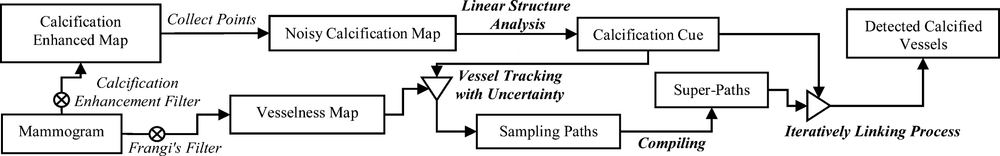
A. Implimentation
1) Calcification Cue with Linear Structure Analysis
In a mammogram, vessels with calcium deposition may appear like bright-railway structures. Compared to other appearance patterns, this kind of bright-parallel-linear pattern can be more certainly labeled as parts of calcified vessels. Accordingly, it will be helpful if we can identify them first in the mammogram. To this end, we first use the technique in [1] to collect a number of calcification candidate points. Subsequently, a parallel linear structure detector is carried out to locate those calcification points with bright-parallel linear patterns. Because those identified points can be parts of the vascular calcium depositions with high confidence, we are able to estimate the distribution of the true vascular calcium depositions in a feature space. With knowledge of this feature distribution, we can specifically define a range to reject points beyond the estimated range.
Detection of Calcification Candidates: The calcification points are detected by using a technique in [1]. The basic idea is to first enhance the calcification signals by computing the difference of two filtered images, F = Fe- Fr
Here, Fe filtered image with a low-pass filter.Fr is obtained by convolving the mammogram with a calcification signal suppression filter:
where Fa is a low-pass smoothing filter and is a high-frequency noise-suppressing filter. Specifically, in his study, Fa is selected as a Gaussian kernel filter with standard deviation of 4.5 (in pixels), and Fb as a mean filter. Then, a global thresholding is applied to collect at most Ncal  highest response points in the enhanced difference image F, as the detected calcifications. This can be achieved by finding the minimal threshold w* that makes the number of the thresholded points no larger than Ncal
Where {pw*} is the point set of the collected calcification candidates, w is an intensity threshold, and Ncal is set empirically to 8000 in this paper.
2)Detection of Parallel Linear Structure Patterns
In the 2-D calcification map built with those detected calcification points {pw*} , the bright railways appear as parallel linear structure patterns. The desired parallel linear structures may be oriented in various directions and usually appear disconnected due to sporadic calcium deposition. Meanwhile, other false detected calcifications may also present. Hence, the detector for parallel linear structures should be invariant to the vessel orientations and also robust to sporadic calcium deposition. To this end, the parallel linear structures will be detected by the following two steps: 1) local orientation estimation and projection profile generation, and 2) projection profile analysis along the estimated local orientation. This demonstrates the whole process of projection profile analysis for the parallel linear structures in calcification map. More details of these two steps are provided below.
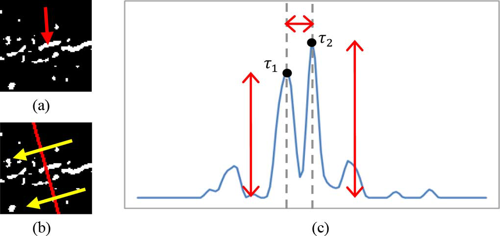 Fig: 4 (b) projection of spatial calcification distribution. (c) the obtained projection profile after smoothing. In (b), the yellow arrows indicate the estimated local orientation. In (c), T1and T2 are the two strongest peaks near to the center of the profile. Red arrows indicate the magnitudes of T1 and T2 , and the distance between T1 andT2 , respectively. In this case, the calcification cluster is part of parallel linear structure
.
3) Vessel Tracking With Uncertainty
The vesselness probability map for tracking is generated by Frangi’s vesselness filter [32]. The vesselness filter [32] consists of two exponential functions, which describe “the second order structureness” and “the tube-like structure,” respectively, and is computed at different scales. Three scales for the standard deviation, i.e., 2, 5, and 8 (pixel), are applied here. The final response of Frangi’s filter is determined by the maximum in the scale space. More details can be found in [32]. We denote the computed vesselness of each pixel as Traversing Direction. The traversing direction specifies the direction of current tracking. Here, we simply model the traversing direction with the (3). The blending factor 
 can be treated as a confidence weighting between the tracking model and the current estimation, similar to Kalman gain in Kalman filter. Since we do not have knowledge about the accuracy of the current estimation, the blending factor is uncertain. Instead of elaborating on calculation of the blending factor, we treat this blending factor as a uniformly distributed random variable, ranging from 0 to 1.
Search Distance. The search distance, such as the variable in the (2), is the factor that defines how far to find a desired next TEP Et+1 .There is no general setting to assert whether a smaller or larger search distance is more likely to lead to un- desired tracking course or premature termination. We describe the uncertainty of the search distance αe with another uniformly distributed random variable, which ranges from 6 to 10 in pixel unit. Because the distribution of vessels may be highly image dependent, the determination of could be difficult.
To this end, we utilize Otsu’s thresholding technique [40] to bipartition the vesselness into valid and invalid groups with threshold π*tm . However, as the common problem shared by many thresholding schemes, there are cases where the vesselness distributions are not bi-modal. In those cases, Otsu’s technique may fail to propose a useful, To compensate this drawback, we blend the obtained optimal with an empirical value 0.1 and have the final vesselness threshold as ½(π*tm+0.1).
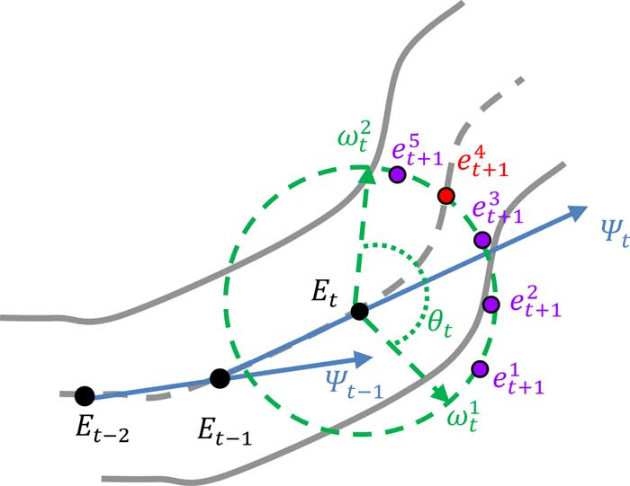
Fig. 4.1The configuration of search window
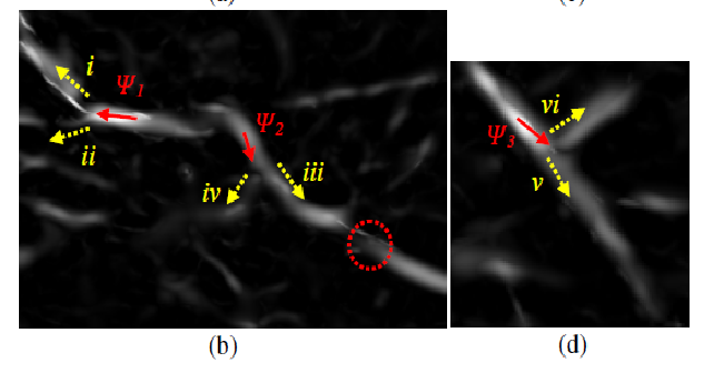
Fig 4.2 Multiple local maxima in vesselness probability(b) are the corresponding vesselness maps. In (b) and (d), the red arrows indicate the tracking directions, while the yellow dotted arrows are the next possible tracking options.
4) Compiling and Linking of Sampling Paths
The multiple-seeded vessel tracking scheme with uncertainty generates many sampling paths and thus requires a post processing step to determine the desired sampling paths. In this section, we cast the post processing step as a compiling and iteratively linking process. As many sampling paths drawn from the distinct seeding points may correlate each other in some degrees, it may be reasonable to group the correlated sampling paths into a “super-path.” Motivated by this, a compiling process is developed to parcel up the sampling paths (with close ending points in both ends) into sets of super-paths. The latter linking process of the super-paths is carried out in an iterative fashion to link up the super-paths: a gradually stricter constraint is iteratively applied in the linkage establishment of more distant pairs of super-paths. Meanwhile, ineligible super-paths are discarded gradually. The iterative linking process will not terminate until no more linkage can be established.
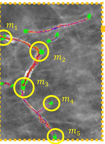
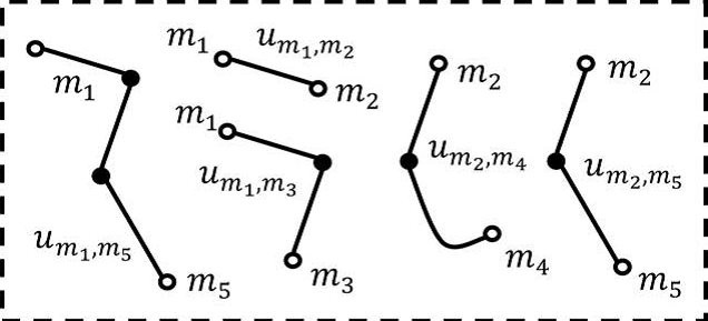
Fig: 4.3 (d) Illustration the concept of compiling the sampling paths into super-paths. There are five clusters of ending points that are identified with yellow circles in (c). Five corresponding super-paths defined by the five clusters of ending points in
V. EXPERIMENTAL RESULTS
The experiments are divided into two parts. The first part focuses on the issues of the major parameter determination in the linear structure analysis, vessel tracking, and linking process. The second part gives the overall performance evaluation of the proposed method. The performance analysis is conducted on 63 full-field digital mammograms, collected in cancer hospital.
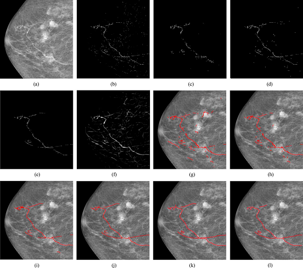
Fig.5 Demonstration on a low-density case.
(a) Original mammography. (b) Calcifications detected with the technique [1]. (c) Identified calcifications with parallel linear structures from (b). (d) Final result of linear structure analysis. (e) Calcifications selected by an expert. (f) Vesselness map. (g) Initial super-paths extracted by the tracking scheme with uncertainty. (h) Super-paths after eliminating ineligible super-paths. (i) Intermediate result of iteratively linking process. (j) Final result. (k), (l) Manual delineations by two experts.
Conclusion
The hypothesis of relating the breast arterial calcification to women’s cardiovascular diseases has not been well studied. For more insightful clinical investigation of this hypothesis, this paper introduces a pioneering computerized method to assist the delineation of calcified vessels in mammography and also the quantization of breast arterial calcification degree. To deal with the respective difficulties, we resort to Monte Carlo method to generate multiple sampling paths with a new vessel tracking with uncertainty scheme. Also, a compiling and linking process is further developed to organize the sampling paths and complete the disconnected calcified vessels. In conclusion, the calcified vessels in mammography can be effectively detected by leveraging two underlying calcification and vesselness cues, along with uncertain vessel tracking and graphical linking techniques. Experiment results indicate that our proposed method can potentially replace the trivial and tedious manual delineations for providing the objective identification of BAC in mammography. The major limitation of the proposed method is the lack of the consideration of breast density. Different parameter settings may be required to various degrees of breast density in mammography.
References
[1] Acha, B., Rangayyan, R.M., Desautels, J.E.L.: Detection of Microcalcifications in Mammograms. In: Suri, J.S., Rangayyan, R.M. (eds.) Recent Advances in Breast Im- aging, Mammography, and Computer-Aided Diagnosis of Breast Cancer. SPIE, Bel- lingham (2006) [2] American College of Radiology (ACR): ACR Breast Imaging Reporting and Data System, Breast Imaging Atlas, 4th edn., Reston, VA, USA (2003) [3] Rangayyan, R.M., Ayres, F.J., Desautels, J.E.L.: A Review of Computer-Aided Di- agnosis of Breast Cancer: Toward the Detection of Subtle Signs. Journal of the Frank- lin Institute 344(3-4), 312–348 (2007) [4] Sampat, M.P., Markey, M.K., Bovik, A.C.: Computer-Aided Detection and Diagnosis in Mammography. In: Bovik, A.C. (ed.) Handbook of Image and Video Processing. Elsevier Academic Press, Amsterdam (2005) [5] de Paredes, E.S.: Atlas of Mammography, 3rd edn. Lippincott Williams & Wilkins, Philadelphia (2007) [6] Cheng, H.D., Shi, X .J., Min, R., Hu, L.M., Cai, X.P., Du, H.N.: Approaches for Automated Detection and Classification of Masses in Mammograms. Pattern Recog- nition 39(4), 646–668 (2006) [7] Rangayyan, R.M.: Biomedical Image Analysis. CRC Press LLC, Boca Raton (2005) [8] Jain, A.K., Duin, R.P.W., Mao, J.: Statistical Pattern Recognition: A Review. IEEE Transactions on Pattern Analysis and Machine Intelligence 22(1), 4–37 (2000) [9] Metz, C.E.: Basic principles of ROC analysis. Seminars in Nuclear Medicine, 283– 298 (October 1978) [10] Long, P.M., Servedio, R.A.: Boosting the Area Under the ROC Curve. In: Advances in Neural Information Processing Systems 20, Conference Proceedings (December 2007) [11] Brzakovic, D., Luo, X.M., Brzakovic, P.: An approach to automated detection of tu-mors in mammograms. IEEE Transactions on Medical Imaging 9(3), 233–241 (1990) [12] Li, L.H., Qian, W., Clarke, L.P., Clark, R.A., Thomas, J.: Improving Mass Detection by Adaptive and Multi-Scale Processing in Digitized Mammograms. Proceedings of ?SPIE—The International Society for Optical Engineering 3661 1, 490–498 (1999) [13] Matsubara, T., Fujita, H., Endo, T., et al.: Development of Mass Detection Algorithm Based on Adaptive Thresholding Technique in Digital Mammograms. In: Doi, K., Giger, M.L., et al. (eds.) pp. 391–396. Elsevier, Amsterdam (1996) [14] Dominguez, A.R., Nandi, A.F.: Enhanced Multi-Level Thresholding Segmentation and Rank Based Region Selection for Detection of Masses in Mammograms. In: IEEE International Conference on Acoustics, Speech and Signal Processing 2007, ?ICASSP 2007, Honolulu, HI, April 15-20, pp. 449–452 (2007) [15] Varela, C., Tahoces, P.G., Méndez, A.J., Souto, M., Vidal, J.J.: Computerized Detec- ?tion of Breast Masses in Digitized Mammograms. Computers in Biology and Medi- cine 37, 214–226 (2007)
Copyright
Copyright © 2024 Preethi M, Rukmini Bhat, Reshma . This is an open access article distributed under the Creative Commons Attribution License, which permits unrestricted use, distribution, and reproduction in any medium, provided the original work is properly cited.

Download Paper
Paper Id : IJRASET66003
Publish Date : 2024-12-18
ISSN : 2321-9653
Publisher Name : IJRASET
DOI Link : Click Here
 Submit Paper Online