Ijraset Journal For Research in Applied Science and Engineering Technology
- Home / Ijraset
- On This Page
- Abstract
- Introduction
- Conclusion
- References
- Copyright
Design of Microstrip Patch Antenna for WSN Application
Authors: K Raghavendra Rao, B. Sudha, M Bhagat Raj Singh, Kavya Karthik
DOI Link: https://doi.org/10.22214/ijraset.2024.63927
Certificate: View Certificate
Abstract
This paper focuses on the design and simulation of a microstrip patch antenna for Wireless Sensor Network (WSN) applications, utilizing HFSS (High-Frequency Structure Simulator) software and an FR-4 epoxy substrate. The objective is to develop an efficient and cost-effective antenna tailored for the 2.4 GHz frequency band, commonly used in WSNs due to its favourable propagation characteristics. The choice of FR-4 epoxy substrate, with a relative dielectric constant (?_R) of 4.4 provides a balance of performance, availability, and cost-effectiveness. These properties are crucial in determining the antenna\'s resonant frequency and overall efficiency. The design process involves optimizing the dimensions of the rectangular microstrip patch antenna to achieve the desired frequency and performance metrics. HFSS simulation tools are employed to model the antenna\'s behaviour, allowing for precise adjustments and performance predictions. Key parameters analysed include return loss (S11), gain, radiation pattern, and bandwidth.
Introduction
I. INTRODUCTION
Micro strip antennas are low-profile antennas. A metal patch mounted at a ground level with a dielectric material in-between constitutes a Micro strip or Patch Antenna. These are very low size antennas having low radiation. Micro strip patch antennas have become more popular in the area of wireless communication The polarization of an antenna is defined as the direction of the electromagnetic fields produced by the antenna as energy radiates away from it. Matching the polarization in both the transmitter and receiver antennas is important in terms of decreasing transmission losses.
A. Microstrip Patch Antenna
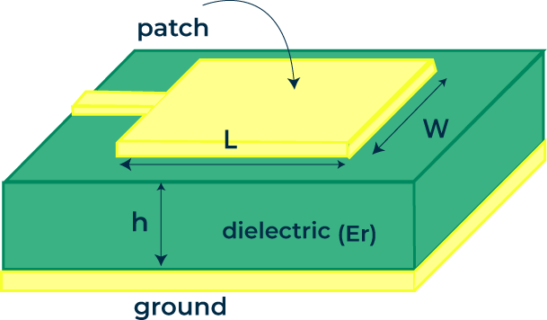
Micro strip antennas are extensively used with the introduction of monolithic microwave integrated circuits (MMIC’s). A metal patch mounted at a ground level with a dielectric material in-between constitutes a Micro strip or Patch Antenna. These are very low size antennas having low radiation. Micro strip patch antennas have become more popular in the area of wireless communication. Antenna is a transitional structure providing transition of EM waves between guided wave and free space wave. Antenna parameters such as reflection co-efficient, VSWR (Voltage Wave Standing Ratio), directivity, Gain, Radiation pattern, bandwidth plays a vital role in choosing the antenna for a specific application.

Fig. 1 Microstrip patch Antenna
II. LITERATURE SURVEY
table 1
referred papers and books
|
BOOK, PAPER REFRENCE AUTHOR |
REFERED PARAMETER |
DESCRIPTION |
|
Substrate, thickness, Bandwidth, Efficiency |
Role of Substrate Thickness: For the proposed antenna with substrate thickness t = 3 mm, the 10 dB bandwidth is 3.08% and the corresponding radiation efficiency is 88.38%. By varying the thickness of the substrate from 3 to 4.25 mm the bandwidth has been increased from 3.08 to 3.92 % but the efficiency has been decreased from 88.38 to 85.37%. With increase in the thickness the loss due to surface waves increases which eventually reduces the efficiency. The numerical values of 10 dB bandwidth and efficiency with the substrate thickness are tabulated. |
|
|
L. Jeth[2]i |
Selection of suitable substrate |
The selection of the substrate material is important in order to predict the antennas general performance. The overall dimensions of the antennas are closely related to its dielectric constant. A high dielectric constant would produce a small antenna dimension. A lower dielectric constant and loss tangent contributed to the high gains. The impedance of the antennas must reach 50 Ohms. |
|
“Broadband Microstrip Antennas”, Girish Kumar,K. P. Ray[3] |
Configuration for MSA,BW,Gain.Substrate thickness |
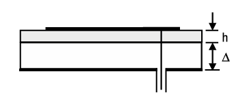
The BW of the MSA is directly proportional to the substrate thickness(h) and inversely proportional to the square root of its dielectric constant. The BW of the MSA increases with an increase in height and a decrease in dielectric constant. The effect of the increase in height and the decrease in dielectric constant can also be realized using the suspended-microstrip configuration. The patch is fabricated on one side of the dielectric substrate, and it is suspended in air with an air gap of Δ. |
We selected suspended configuration because it offers several advantages over traditional microstrip patch antennas and other broadband antennas designs for parameters like. Enhanced Bandwidth, Cost-Effective, and Practical. Using air as part of the dielectric reduces the material cost. The use of air as a part of the dielectric reduces the overall dielectric losses, leading to higher radiation efficiency. By suspending the patch above the ground plane, the effective height of the antenna increases, which reduces the substrate effects and thereby increases the bandwidth. introducing an air gap between the patch and the substrate further enhances the bandwidth by lowering the effective dielectric constant. This results in wider impedance bandwidth compared to conventional microstrip patch antennas.
III. METHODOLOGY
In the current work, design of an antenna with 100 MHz characteristics has been outlined. It was simulated using a FR4 substrate. The dielectric constant of the substrate was 4.4 with a thickness of 1.6 mm and air substrate of thickness 5 mm to get an equivalent dielectric constant of around.1.3 to get a bandwidth of around 100MHz in the Wi-Fi (2.4GHz) frequency band. Another antenna was designed and simulated for 100 MHz bandwidth using only FR4 as the substrate without using air as another dielectric constant to compare various characteristics such as VSWR, Reflection Coefficient, Bandwidth and Gain. The selection. of width and the length of the antenna was in accordance to tuning it to respective frequency band. The patch length value of the antenna has been outlined to be at half of the wavelength of the guide relating to a frequency of 2.4Ghz. Impedance matching was achieved between the antenna and the port using coaxial type feeding technique. The coaxial type of feed is placed at the edge of the patch to attain the required value of around 50 ohm impedance.
For Calculating Dimensions of the patch the following Formulas are used. These formulas remain the same for both designs. The length of the patch is almost about half the wavelength of the operating frequency. The width of the patch is related to the bandwidth of the antenna. It is directional proportional to the bandwidth of the antenna. The thickness is also directional proportional to the bandwidth, but it also decreases the efficiency of the antenna. Based on the requirement, the parameters are adjusted. the formulas for calculating Parameters are given
|
εe=(εR+1)2+(εR-1)21+10hw-12 |
… (1) |
|
L=Le-2ΔL |
…(2) |
|
ΔL=hεe |
…(3) |
|
Le=c2F0εe |
…(4) |
|
w=c2F0εR+12 |
…(5) |
|
εeq=εRh+εRΔ εRΔ+h |
…(6) |

Fig. 2 Suspended Configuration
Equation (1)[3] represents the effective dielectric constant (εe ) in terms of dielectric constant of the substrate (εR
 ), height or thickness of the substrate (h
 ) and width of the patch (w
 )
)
Equation (2)[4] is used for calculating the physical length of the patch (L ). It is slightly smaller than the effective length (Le
 ) of the substrate.
Equation (3)[3] is for calculating extension length (ΔL ) of the patch used for calculating physical length.
Equation (4)[4] is used for effective length calculation. It is inversely proportional to the operating frequency (F0 ) and effective dielectric constant of the substrate.
Equation (5)[3] is used as a starting point for calculating the width of the patch for
the operating frequency (in our case 2.4GHz) and is fine-tuned through simulations.
Equation (6)[3] is used to calculate the equivalent dielectric constant between the ground plane and the patch. It is related to the thickness of the substrate and air gap (Δ ) as shown.
A. Design flow

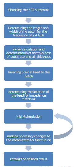
Fig.3 Design flow process for the Rectangular Microstrip Patch antenna
Fig. 3 shows the process for designing a Rectangular Microstrip Patch Antenna and simulating the results.
IV. RESULTS
The results were simulated using HFSS and Gain, Reflection Coefficient, VSWR , Radiation Pattern and Bandwidth were plotted
A. Gain Plot
From Fig. 4 the designed microstrip patch antenna exhibits a maximum gain of 10 dB, as determined through simulations using Ansys HFSS software. The gain is primarily concentrated along the main lobe of the radiation pattern, which is oriented in the positive Z-axis, demonstrating strong directional performance. The radiation pattern shows minimal side and back lobes, which reflects the antenna's good directivity and efficiency, with reduced interference from unwanted radiation. This indicates that the antenna is well-suited for applications requiring focused energy transmission in a specific direction.
 Fig. 4 Gain Plot
B. Reflection Coefficient

Fig. 5 Reflection Coefficient
Through Simulation the reflection coefficient was analyzed (Fig. 5). The reflection coefficient curve indicates how well the antenna is impedance-matched at different frequencies. The minimum reflection coefficient was observed at 2.4 GHz with a value of -18.5798 dB, which suggests an excellent match with minimal power loss. The operational bandwidth was determined to be 140.7 MHz, ranging from approximately 2.3266 GHz to 2.4673 GHz. This bandwidth covers the 2.4 GHz ISM band, making the antenna suitable for applications such as Wi-Fi, Bluetooth, and Wireless Sensor Networks (WSNs). The results confirm that the antenna operates efficiently within this frequency range, ensuring effective signal transmission and reception.
C. VSWR Plot
The Voltage Standing Wave Ratio (VSWR) of the microstrip patch antenna was analysed to evaluate its impedance matching performance. The plot generated using Ansys HFSS software (Fig. 6) shows that the minimum VSWR is 1.2670 at 2.4000 GHz, indicating optimal impedance matching with minimal signal reflection and maximum power transfer. The operational bandwidth, where the VSWR remains below 2, spans roughly from 2.3216 GHz to 2.4724 GHz, covering a range of 150.8 MHz. This bandwidth effectively includes the 2.4 GHz ISM band.
 Fig. 6 VSWR Plot
D. Radiation Pattern

Fig. 7 Radiation Pattern
In Fig. 7 the red curve represents the radiation pattern in the E-plane (Phi = 0 degrees), while the green curve represents the pattern in the H-plane (Phi = 90 degrees). Both patterns indicate directional radiation rather than isotropic, with the main lobes showing where the antenna radiates most of its power. The beamwidth, indicated by the width of the main lobes, reflects the angular width where the radiation power drops to half its maximum value. Both curves display side lobes, which contribute to unwanted radiation and potential interference, and back lobes, though typically weaker. The maximum gain is observed at the peaks of the main lobes. Comparing the two curves reveals differences in radiation patterns between the orthogonal planes, with the H-plane (green) exhibiting a broader beamwidth than the E-plane (red), suggesting varied polarization and radiation characteristics with orientation.
E. Directivity
The directivity is a critical measure of how well the antenna focuses energy in a particular direction. The maximum directivity achieved is 10.05 dB, as represented by the red areas in the 3D plot. The minimum directivity, represented by blue and green colors, is -31.89 dB. The plot shows that the antenna's main lobe, where the highest directivity occurs, is oriented along a specific axis, with minimum side lobes present, indicating very less energy is radiated in other directions.
Conclusion
The designed microstrip patch antenna meets the key performance criteria for WSN applications, including: 1) Directional Radiation: The antenna provides a directional radiation pattern with sufficient gain and directivity, ensuring effective communication in targeted directions, which is crucial for sensor networks. 2) Frequency Compatibility: Operating at 2.4 GHz, the antenna is well-suited for WSNs, providing compatibility with widely used communication protocols like Zigbee, Wi-Fi, and Bluetooth. 3) Efficiency and Reliability: The antenna design ensures efficient radiation with minimal losses, contributing to reliable data transmission in the network.
References
[1] 2.4 GHz Circularly polarized Microstrip Patch Antenna with Diagonal Structural Symmetry, G Guru Varun Nitin, Divyabramham Kandimalla [2] Performance Analysis of Rectangular Microstrip Patch Antenna with Different Substrate Material at 2.4 GHz for WLAN Applications, Zhou Chen Fei, Permesh ,L.Jethi [3] Broadband Microstrip Antennas, Girish Kumar,K. P. Ray [4] Design of Directional Two L shaped Microstrip Patch Antenna for WSN Applications Using Sea Lion Optimization Algorithm, Robin George and Thomas Anita Jones Mary
Copyright
Copyright © 2024 K Raghavendra Rao, B. Sudha, M Bhagat Raj Singh, Kavya Karthik. This is an open access article distributed under the Creative Commons Attribution License, which permits unrestricted use, distribution, and reproduction in any medium, provided the original work is properly cited.

Download Paper
Paper Id : IJRASET63927
Publish Date : 2024-08-09
ISSN : 2321-9653
Publisher Name : IJRASET
DOI Link : Click Here
 Submit Paper Online


 The suspended configuration consisting of two dielectric layers can be replaced by a single layer of equivalent dielectric constant Eeq of thickness h + Δ
 .
.


